How to Calibrate Your Metal Miter Saw for Angle Cuts (Fix)
I remember the first heavy-duty equipment trailer I built. I had spent a week calculating the structural metal load capacity and selecting the right ASTM A36 steel channels. I was confident. But when I began fitting the frame, the corners didn’t close. There was a tiny wedge-shaped gap at the heel of the miter. I figured the weld would just fill it. During a later inspection, we found that the uneven gap caused a massive heat-affected zone weakness because I had to dump too much filler metal into the joint. That experience taught me that structural integrity starts long before the welder is turned on. It starts with the mechanical alignment of your cutting equipment.
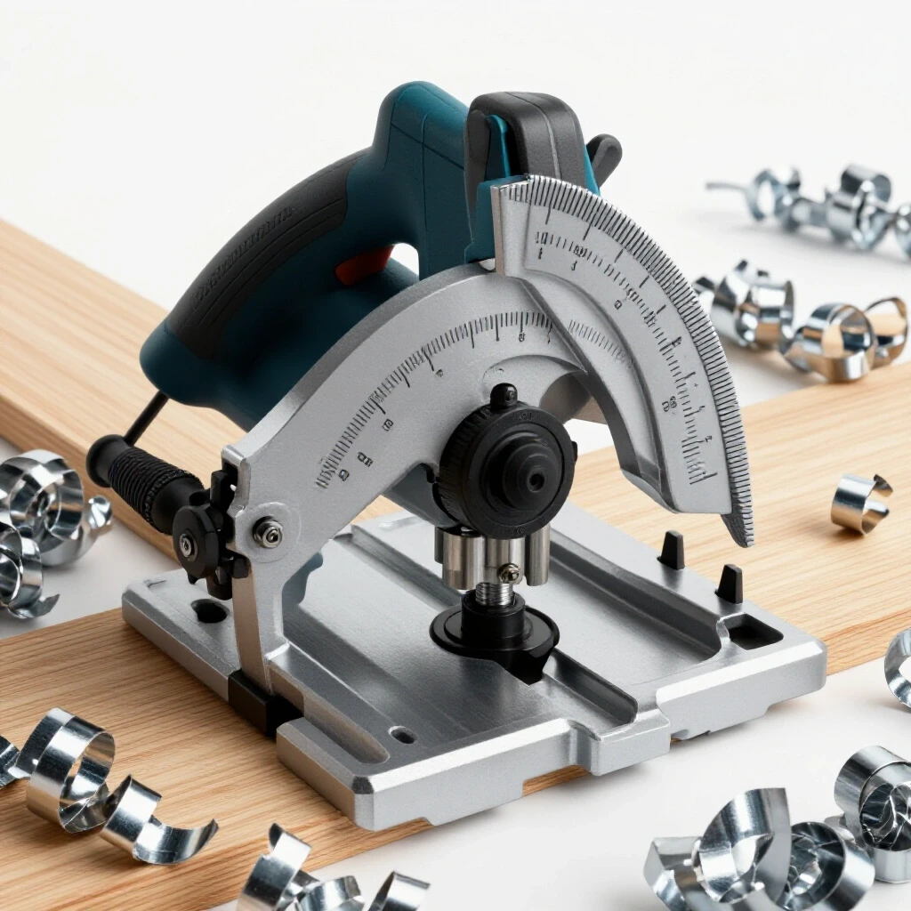
In my 14 years on the shop floor, I have seen how a deviation of even half a degree can compromise a load path. When your cuts are not square, the forces in a finished structure do not travel through the center of the members. Instead, they create eccentric loading, which can lead to brittle fracture under stress. Ensuring your saw is perfectly aligned is not about being a perfectionist; it is about managing the physics of the build.
The Relationship Between Geometric Precision and Structural Integrity
Structural integrity refers to the ability of a joined assembly to hold its intended load without failing. In metal fabrication, this depends on how well the surfaces of two components meet. Precise angles ensure that the weld throat is consistent and that the base metals transfer energy directly through the intended load paths.
When we talk about the structural metal load capacity of a frame, we assume the joints are flush. If a saw is cutting at 89.5 degrees instead of 90, you are left with a gap. To bridge that gap, you often increase the heat or the amount of filler. This creates a larger heat-affected zone weakness, a region where the metal’s grain structure has been altered by heat, making it more prone to cracking. By aligning your equipment, you minimize the volume of weld metal needed and maintain the original properties of the steel.
Why Angular Deviation Leads to Joint Failure
Angular deviation is the difference between the intended cut angle and the actual result. Even a small error of 0.5 degrees creates a cumulative gap that grows with the width of the material. This gap forces the welder to use a wider weave, increasing internal stress and the risk of welding defects like undercut or lack of fusion.
If you are building a structure meant to withstand 10,000 PSI, a poorly fitted joint can reduce that capacity by 30% or more. The weld becomes a “stress riser,” a point where forces concentrate rather than flow. This is why I treat the alignment of my saw fence and blade as a critical part of my welding defect troubleshooting process. If the fit-up is perfect, the weld has the best chance of meeting its design strength.
| Angular Error (Degrees) | Gap at Edge (2-inch Tubing) | Stress Concentration Factor |
|---|---|---|
| 0.1° | 0.003″ | 1.05 |
| 0.5° | 0.017″ | 1.25 |
| 1.0° | 0.035″ | 1.60 |
| 2.0° | 0.070″ | 2.10 |
Squaring the Fence to the Cutting Path
The fence is the vertical surface that supports your material during a cut. Squaring the fence involves ensuring it is perfectly perpendicular to the plane of the saw blade. This is the primary reference point for every miter and bevel cut you will make on the machine.
I have found that many intermediate fabricators overlook the fence, assuming it was set correctly at the factory. However, shipping, thermal expansion, and the vibration of cutting ferrous materials can shift these components. To check this, I use a precision machinist square. Place one leg of the square against the fence and the other against the body of the blade (avoiding the teeth). If you see light between the square and the blade, your fence is out of alignment and must be adjusted.
Verifying Fence Planarity and Perpendicularity
Fence planarity is the flatness of the fence across its entire length, while perpendicularity is its 90-degree relationship to the saw table. If the fence is bowed or leaning, the material will “rock” during the cut, leading to a compound error that is nearly impossible to fix with a welder.
To fix a leaning fence, you must check the mounting bolts located at the rear of the saw. Loosen them slightly and use a thin shim or the built-in adjustment screws to bring the fence back to a true 90-degree vertical. I always perform this check before moving on to miter adjustments. A fence that isn’t square to the table will cause your 45-degree miters to be “long” on one side, creating a joint that won’t sit flat on a welding table.
- Clean the table and fence of all metal chips and burrs.
- Use a high-quality machinist square (Grade B or better).
- Check both the left and right sides of the fence if it is a split design.
- Tighten bolts in a star pattern to prevent shifting during final torque.
Calibrating Miter Detents for Repeatable Accuracy
Miter detents are the pre-set locking positions on a saw, such as 0, 22.5, and 45 degrees. Calibrating these involves adjusting the detent plate or the locking pin so that when the saw “clicks” into place, the blade is at the exact angle indicated on the scale.
Interestingly, the detent is often just a piece of stamped steel. Over time, the pin can wear down the edges of the notch, leading to “slop” or play in the handle. When I inspect industrial saws, I look for this play first. If the saw moves even a fraction of a millimeter after it is locked, your structural joints will suffer. You can usually adjust the detent plate by loosening its mounting screws and shifting it until the blade is perfectly square to the fence at the zero mark.
The Iterative Flip Test for 90-Degree Verification
The flip test is a diagnostic method used to double the perceived error of a cut, making it easier to see and correct. By cutting a piece of metal and flipping one half over to meet the other, any deviation from 90 degrees is magnified by two.
To perform this, take a piece of square tubing and make a 90-degree cut. Take the piece you just cut off, flip it 180 degrees, and butt the two cut ends together against a straight edge. If the saw was perfectly square, the two pieces will form a perfectly straight line. If there is a gap at the front or back, your saw is off by half of that gap. This is the most reliable way to verify your saw without relying solely on a square.
- Secure a scrap piece of 2-inch square tubing.
- Perform a standard 90-degree cut.
- Flip the cut piece over (rotate it 180 degrees).
- Push both pieces against the fence.
- Inspect the joint for any light passing through.
- Adjust the miter scale pointer or detent plate based on the gap.
Adjusting Bevel Stops for Compound Joints
Bevel stops are the mechanical limits that control the tilt of the saw head. Calibrating these is essential for compound miters, where the metal is cut at an angle across both its width and its thickness, common in roof trusses or complex frames.
In my experience, bevel adjustments are more prone to drifting than miter adjustments because the weight of the motor constantly pulls on the pivot point. I use a digital angle finder for this process. Place the magnetic base on the saw table to “zero” it, then attach it to the blade. Tilt the head to 45 degrees and check the reading. If it says 44.7, you need to adjust the stop bolt—usually a long hex bolt with a jam nut located near the rear pivot.
Using Digital Angle Finders vs. Fixed Squares
A digital angle finder provides a numerical value, often to the tenth of a degree, while a fixed square relies on visual inspection. For structural work, the digital tool is superior because it allows you to quantify the error and make precise, incremental corrections.
However, you must be careful with digital tools. They measure the angle relative to the earth’s gravity or the surface they were zeroed on. If your saw table is covered in grinding dust or isn’t perfectly flat, the reading will be false. I always wipe the table with a clean rag and verify the “zero” on the table surface before every measurement. This ensures that the blade-to-table relationship is the only variable being measured.
- Zero the digital gauge on the saw table, not the floor.
- Ensure the gauge is not resting on the teeth of the blade.
- Check the 0-degree (vertical) stop first.
- Check the 45-degree stop and adjust the limit bolt.
- Re-check the 0-degree stop, as adjusting one can sometimes nudge the other.
Compensating for Material Deflection and Clamping
Material deflection occurs when the pressure of the saw’s clamp or the weight of the metal itself deforms the workpiece during the cut. Even a perfectly calibrated saw will produce an inaccurate cut if the metal is not held correctly.
When I was investigating a series of failures in a custom racking system, we found that the fabricator was over-tightening the screw clamp on thin-walled tubing. This was bowing the metal slightly. When the blade passed through, it cut a straight line through a curved piece of steel. Once the clamp was released, the metal snapped back, and the cut was no longer square. Using “V-blocks” or sacrificial spacers can help distribute clamping pressure and keep the material true to the fence.
Managing Long Stock and Outfeed Support
Outfeed support refers to the stands or tables used to hold the long end of a metal bar. If the end of a 20-foot stick of steel is hanging off the saw, it acts as a lever, lifting the material off the saw table near the blade.
This creates a “slanted” cut that looks like a bevel error but is actually caused by poor material handling. I always use adjustable rollers to ensure the metal is level with the saw table. If you don’t have rollers, even a simple sawhorse with a shim can work. The goal is to eliminate any vertical or horizontal tension on the piece being cut. This prevents the blade from “walking” or binding, which is a major cause of jagged, inaccurate edges.
| Support Type | Best For | Risk Factor |
|---|---|---|
| Roller Stands | Long, heavy beams | Can tip if not centered |
| Fixed Tables | Repeatable small parts | Requires perfectly level floor |
| Manual Shimming | Emergency/Field work | High chance of human error |
| V-Blocks | Round tubing/Pipe | Must be aligned with fence |
Verification Checklist for Structural Accuracy
Before I start any major project involving heavy loads, I run through a specific checklist. This ensures that my machine is ready to produce the high-quality joints required for structural safety.
- Clear the Deck: Remove all metal shavings from the fence and table. Even a single chip can kick a part out by 0.5 degrees.
- Blade Inspection: Ensure the blade is flat and not warped. A warped blade will “flutter,” creating a cut wider than the kerf.
- Fence Squareness: Use the machinist square to verify the 90-degree relationship between the fence and blade.
- Table Level: Check that the left and right sides of the saw table are on the same plane.
- Pointer Calibration: Once the blade is square, ensure the red pointer on the scale actually points to zero.
- Test Cut: Perform the flip test on a piece of scrap material from the same batch you intend to use.
- Clamping Pressure: Verify that the clamp holds the material firmly without deforming the profile.
By following these steps, you reduce the likelihood of encountering welding defect troubleshooting issues later. A project that starts with accurate geometry is far easier to weld, stays flatter during the cooling process, and ultimately achieves its intended structural metal load capacity.
Frequently Asked Questions
Why does my saw cut square on small pieces but not on large ones?
This is usually a sign of fence misalignment or lack of outfeed support. On small pieces, the material sits flat against a small section of the fence. On larger pieces, any bow in the fence or any “pull” from the weight of the overhanging metal will magnify the error. Check the planarity of your fence with a long straight edge.
How often should I recalibrate my metal miter saw?
I recommend a quick check at the start of every new project or after any “event,” such as a blade bind or moving the saw. For high-precision structural work, I check the 90-degree squareness every morning. Vibration from cutting steel is much higher than wood, which causes bolts to loosen over time.
Can a dull blade affect the accuracy of my angle cuts?
While the guide focuses on mechanical calibration, a dull blade can cause “blade lead.” This is when the blade seeks the path of least resistance and wanders to one side during the cut. This creates a curved surface rather than a flat one, making it look like the saw is out of calibration when the issue is actually the cutting tool.
What is the best tool for checking 45-degree angles?
A dedicated 45-degree machinist square or a high-quality combination square is excellent for visual checks. However, for the highest accuracy, I prefer using a digital angle finder or the “four-cut method,” where you cut a square frame and see if the last joint closes perfectly.
My saw “clicks” into 0 degrees but it’s still off. What do I do?
The detent plate is likely out of position. Loosen the screws holding the notched plate to the base of the saw. Move the saw handle until the blade is perfectly square to the fence using your machinist square. While holding it there, slide the detent plate until the pin drops into the 0-degree notch, then tighten the screws.
Does the thickness of the metal affect the calibration?
The calibration remains the same, but the “perceived” error increases with thickness. On a thin 1/8-inch strap, a 1-degree error is barely visible. On a 4-inch heavy-wall tube, that same 1-degree error creates a massive gap. Always calibrate using the thickest material your project requires to ensure the error is minimized.
How do I fix a saw that cuts a bevel when it’s supposed to be 90 degrees?
This is an issue with the vertical stop. Most saws have a bolt that acts as a physical stop for the 0-degree bevel position. Loosen the jam nut on this bolt, use a square to set the blade perfectly vertical to the table, and then turn the bolt until it touches the saw head. Tighten the jam nut to lock it in.
Why do my mitered corners have gaps at the top but not the bottom?
This is a “compound” error. It means your blade is not square to the table (a bevel error) or your material is lifting off the table during the cut. Ensure your bevel is set to exactly 0 degrees and that you are using downward clamping pressure to keep the workpiece flat against the table.
Is it better to trust the built-in scale or my own tools?
Always trust your own precision tools. Built-in scales are often stickers or cast-in marks that can be slightly off from the factory. Use the scale as a general guide, but use your machinist square and digital angle finder for the final verification.
Can I use a wood miter saw for metal if I change the blade?
Generally, no. Metal-cutting saws (cold saws or dry-cut saws) run at much lower RPMs than wood saws. Using a wood saw on metal creates excessive heat, which can warp the blade and the saw’s pivot points, making it impossible to maintain calibration. Always use a saw designed for the material’s specific mechanical properties.
(This article was written by one of our staff writers, James Harlan. Visit our Meet the Team page to learn more about the author and their expertise.)