How to Control Heat Expansion When Welding Aluminum (Guide)
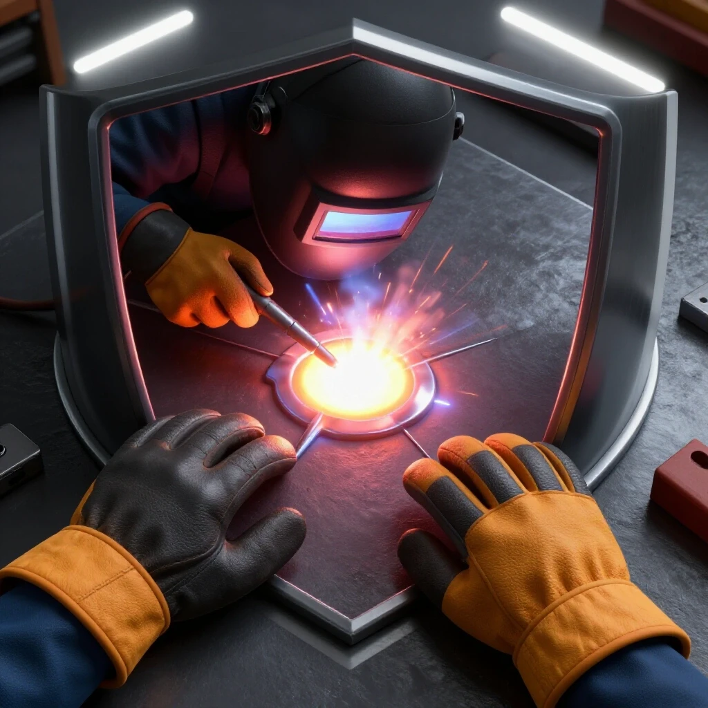
I remember standing over a 20-foot aluminum marine manifold years ago, watching a perfectly straight assembly turn into a banana in under twenty minutes. I had followed the prints, but I hadn’t respected the physics of the material. Aluminum is a different beast than steel; it has a high rate of thermal expansion and conducts heat with incredible efficiency. When you apply a welding arc, the metal doesn’t just melt at the joint; the entire piece begins to grow and shift almost immediately.
Over 15 years of diagnosing fabrication failures, I have learned that you cannot fight aluminum with brute force. If you try to simply clamp it into submission without a thermal management plan, you will likely end up with cracked welds or a permanently warped structure. Troubleshooting these issues requires a systematic approach where we isolate variables like travel speed, joint fit-up, and weld sequencing. My goal is to help you move away from guesswork and toward a repeatable, diagnostic method for maintaining dimensional stability.
Establishing a Diagnostic Framework for Thermal Movement
Thermal movement diagnostics involve analyzing how heat energy transfers from the welding arc into the surrounding material. By understanding the relationship between heat input and material volume, fabricators can predict where expansion will occur and implement preventative measures. This framework relies on measuring temperature gradients and observing physical displacement across the assembly.
When I start a new diagnostic log for a warping issue, I look at the “Heat-Affected Zone” or HAZ. In aluminum, this zone is often much wider than in other metals because the material pulls heat away from the weld puddle so fast. To control this, I use a three-step observation process:
- Initial State Mapping: Measure the assembly with a dial indicator or laser level before any heat is applied.
- Point-Source Monitoring: Use an infrared thermometer to track how far the heat travels from the weld path after a three-inch bead.
- Displacement Tracking: Re-measure the assembly at specific intervals to see exactly which weld caused the most movement.
Building this baseline allows you to see the “why” behind the warp. If the metal moves 0.050 inches after the first pass, you know your clamping or heat input is the root cause. This data-driven approach stops you from chasing “ghosts” in your technique.
Optimizing Fixturing and Mechanical Restraint
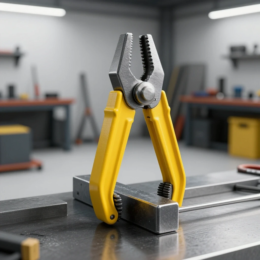
Mechanical restraint involves using rigid jigs, heavy clamps, and backing bars to physically limit the material’s ability to expand during the heating cycle. This technique requires a balance between holding the part firmly and allowing enough micro-movement to prevent internal stress cracking. Proper fixturing acts as a heat sink, pulling excess energy out of the workpiece.
I often see fabricators use light-duty clamps that flex as soon as the aluminum starts to grow. In my shop, I use thick copper or aluminum backing bars whenever possible. These bars serve a dual purpose: they hold the part in a fixed plane and they absorb heat. Because copper has higher thermal conductivity than aluminum, it sucks the heat out of the weld zone, which limits the total expansion of the workpiece.
- Use clamps with at least 500 lbs of clamping force for structural frames.
- Space clamps no more than 8 inches apart on thin-gauge sheets.
- Ensure the fixture table is perfectly flat within 0.005 inches over 4 feet.
Interestingly, over-clamping can be just as dangerous as under-clamping. If the metal is locked down too tightly and cannot move at all, the internal stresses can exceed the tensile strength of the cooling weld. This usually results in a centerline crack. I look for a “firm but not crushed” setup, often using sacrificial tack-welded tabs to hold critical alignments.
Managing Heat Input Through Travel Speed and Amperage
Heat input management is the process of calculating the total energy delivered to a joint to minimize the volume of metal that reaches expansion temperatures. This is achieved by balancing high amperage with fast travel speeds to create a narrow, concentrated weld pool. Lowering the total “on-time” of the arc reduces the overall thermal soak of the part.
Many intermediate fabricators think that lowering the amperage will reduce warping. In my experience, the opposite is often true. If the amperage is too low, you have to move slower to get the puddle to flow. This slow movement allows heat to soak deep into the surrounding metal, causing massive expansion. I prefer to “get in and get out.” By using higher current and moving the torch faster, I create a localized melt that solidifies before the rest of the part even knows it’s hot.
| Factor | High Heat/Slow Speed | Low Heat/Fast Speed |
|---|---|---|
| HAZ Width | Wide (Over 1 inch) | Narrow (Under 0.5 inch) |
| Expansion Rate | High Displacement | Controlled Displacement |
| Penetration | Deep/Wide | Controlled/Targeted |
| Risk of Cracking | Moderate | Low |
A good metric to track is your “bead-per-minute” rate. If I am welding 1/8-inch aluminum, I aim for a travel speed that keeps the HAZ focused within 3/8 of an inch from the toe of the weld. If I see the heat tint spreading further, I know I need to increase my travel speed or adjust my pulse settings to reduce the average current.
Strategic Sequencing and Intermittent Welding Patterns
Sequencing is the practice of alternating the location and direction of welds to balance the pulling forces created by thermal contraction. By using intermittent or “stitch” welds, a fabricator can distribute heat more evenly across the entire structure. This prevents any single area from becoming a localized hot spot that pulls the assembly out of alignment.
When I’m troubleshooting a frame that keeps twisting, the first thing I look at is the weld order. If you weld a long seam from left to right, the metal will expand ahead of the arc, causing the gap to close or the plates to overlap. I use the “backstepping” method to counter this. Instead of one long 10-inch bead, I weld five 2-inch segments, starting each one ahead of the previous and welding back toward the finished bead.
- Weld from the center of the assembly outward to the edges.
- Alternate sides of the joint to balance the “pull” of the cooling metal.
- Allow the part to return to a touchable temperature (roughly 150°F) between long passes.
This “leapfrog” approach is a fundamental diagnostic fix for structural misalignment. If a part is bowing to the left, my next sequence will be on the right side to pull it back. It is a constant game of tug-of-war where the goal is a tie.
Real-Time Monitoring with Diagnostic Tools
Modern diagnostic tools allow fabricators to see thermal patterns that are invisible to the naked eye, providing a data-driven way to adjust techniques. Using infrared cameras, digital thermometers, and displacement gauges, you can identify “hot zones” before they cause permanent deformation. These tools turn subjective “feel” into objective measurements.
I recently worked on a large aluminum tank where the baffles were warping during installation. We used a smartphone-connected thermal imager to watch the heat soak in real-time. We discovered that heat was building up in a corner where three plates met, causing a localized expansion of nearly 0.080 inches. By identifying this “heat trap,” we adjusted our sequence to weld that corner last, allowing the rest of the structure to act as a rigid cage.
- Infrared Thermometer: Check interpass temperatures to ensure they stay below 200°F for 6000-series alloys.
- Digital Dial Indicators: Mount these on the ends of long parts to see movement as it happens.
- Tempiliks (Temperature Crayons): Use these as a low-cost way to mark “no-go” zones for heat.
Tracking these metrics in a simple spreadsheet helps you see patterns. For example, if you notice that every time the temperature hits 250°F, your alignment shifts by 0.030 inches, you have found your “thermal limit.” You can then adjust your cooling intervals or heat sinks to stay below that threshold.
Diagnosing Joint Fit-Up and Gap Consistency
Joint fit-up refers to the physical relationship between two mating surfaces before welding, including the gap width and root face alignment. In aluminum, inconsistent gaps lead to uneven heat absorption, which is a primary driver of unpredictable expansion and warping. A tight, uniform fit-up ensures that heat flows predictably across the joint.
In my diagnostic logs, “poor fit-up” is the number one cause of unexpected movement. If you have a 1/16-inch gap at one end of a seam and a 1/8-inch gap at the other, the volume of filler metal required changes. More filler metal means more heat, and more heat means more expansion. I aim for a consistent gap of no more than 0.005 to 0.010 inches for precision work.
- Check for “daylight” in the joint using a strong flashlight behind the plates.
- Use a feeler gauge to verify that the gap is uniform across the entire length.
- Ensure the edges are square and free of burrs that could trap air or contaminants.
When the fit-up is perfect, the arc energy is distributed evenly. This makes the thermal expansion symmetrical. If I find a gap that is too wide, I don’t just “fill it.” I will often stop, rework the piece, or use a sacrificial backing strip to manage the heat. It is always faster to fix the fit-up than it is to fix a warped assembly.
The Role of Tack Welding in Dimensional Control
Tack welding is the process of using small, temporary welds to lock parts into position before the final structural beads are applied. For aluminum, tacks must be larger and more frequent than for steel because they must resist the material’s high expansion forces. Properly placed tacks act as “anchors” that maintain the integrity of the assembly during the main welding phase.
I’ve seen many tacks snap like glass because they were too small. Aluminum shrinks significantly as it cools, and a tiny tack won’t hold the weight of a moving plate. I follow a “rule of four” for aluminum: tacks should be four times the thickness of the material in length. If I’m welding 1/8-inch plate, my tacks are at least 1/2-inch long.
- Place tacks every 2 to 4 inches on thin material.
- Always tack both ends of a joint before filling the middle.
- Inspect tacks for cracks before starting the final pass; a cracked tack is a failed anchor.
If a tack fails during the weld, the entire part will shift instantly. In my troubleshooting process, if I see a part “jumping” or “popping” during a pass, I know my tacks were insufficient. I stop immediately, realign, and add more robust anchors. It is a diagnostic sign that the thermal expansion forces have overwhelmed the mechanical restraints.
Troubleshooting Common Thermal Defects
Identifying the root cause of thermal defects requires distinguishing between material failure, such as cracking, and geometric failure, such as warping. By analyzing the location and shape of the defect, a fabricator can determine if the issue was caused by excessive heat, improper cooling, or lack of restraint. This systematic isolation prevents the recurrence of the same error.
When I see a “saddle warp” (where the ends of a plate curl up), I know the top of the weld cooled and contracted faster than the bottom. This is a heat-balance issue. To fix this, I look at my cooling rates. If the part is on a cold steel table, the bottom cools instantly while the top stays hot. Using an insulated surface or a heated platen can sometimes help equalize this, though in most shop environments, simply managing the bead sequence is more practical.
| Defect Observed | Likely Root Cause | Diagnostic Fix |
|---|---|---|
| Centerline Crack | Excessive Restraint / Too much heat | Increase travel speed; allow slight movement. |
| Bowing / Camber | Unbalanced welding sequence | Use backstepping; alternate sides of the part. |
| Angular Distortion | High heat soak in the joint | Use copper chill bars; increase amperage/speed. |
| Longitudinal Shrink | Long, continuous weld beads | Use intermittent stitch welds. |
By categorizing these defects, you can build a “cheat sheet” for your specific shop setup. Every machine and every operator has a different thermal signature. Documenting these failures transforms a frustrating mistake into a valuable data point for future projects.
FAQ: Controlling Thermal Expansion in Aluminum
Why does aluminum warp so much more than mild steel? Aluminum has a coefficient of thermal expansion that is roughly double that of steel. Additionally, its high thermal conductivity means heat travels through the part very quickly. This combination causes larger areas of the metal to grow and move in response to the welding arc, making dimensional control much more difficult.
How do I know if my travel speed is fast enough to prevent warping? Observe the width of the Heat-Affected Zone (the discolored area next to the weld). If the HAZ is more than three times the width of the weld bead, you are likely moving too slowly. Increasing your amperage and travel speed will concentrate the heat, resulting in a narrower HAZ and less total expansion.
Can I use water to cool the aluminum between passes? I generally advise against water quenching for 6000-series aluminum alloys. Rapid cooling can cause the metal to become brittle or trap internal stresses that lead to cracking later. It is better to use “air cooling” or place the part on a large metal heat sink (like a thick aluminum plate) to dissipate heat naturally but quickly.
What is the best way to prevent a long aluminum sheet from “oil-canning”? “Oil-canning” or buckling is caused by the edges of the sheet expanding while the center stays cool. To prevent this, use a strong clamping fixture that covers as much surface area as possible. Also, use a “staggered” welding sequence where you jump around the perimeter rather than welding in a straight line.
Should I preheat aluminum to stop it from moving? Preheating is usually done to ensure proper fusion on thick sections, but it can actually make warping worse on thinner materials. If you do preheat, keep it uniform across the entire part and stay below 200°F. Uneven preheating creates its own set of expansion problems that can fight your welding alignment.
How many tacks are “enough” for a three-foot seam? For aluminum, I recommend a tack every 3 to 4 inches. If the material is very thin (under 1/16-inch), you might need them even closer. The goal is to make the assembly act as one solid unit. If you see the gap opening or closing between tacks, you need more anchors.
Does the type of shielding gas affect heat expansion? While the gas itself doesn’t change the expansion rate, different gases (like Argon vs. Helium mixes) affect the heat profile of the arc. Helium increases the heat input, which can be useful for thick sections but might increase warping on thin ones. For most troubleshooting, sticking with pure Argon allows for a more stable, predictable heat zone.
What should I do if the part has already warped? This guide focuses on prevention because aluminum is very difficult to “correct” once it has moved. However, the first diagnostic step is to measure the deviation. If it is within your tolerance, you might be able to compensate in the next assembly step. If not, you must analyze your sequence and heat input to ensure the next part doesn’t suffer the same fate.
How do chill bars work if they aren’t clamped directly to the weld? Chill bars work through thermal conduction. Even if they are an inch away from the bead, they provide a path for the heat to escape the workpiece. The closer they are, the more effective they will be. I often use heavy brass or copper blocks placed right next to my weld path to “soak up” the excess energy.
Does the alloy of the aluminum change how much it expands? Most common welding alloys (like 5052 and 6061) have similar expansion rates. However, their sensitivity to “hot cracking” varies. 6061 is more prone to cracking if it is overly restrained during expansion, whereas 5000-series alloys are a bit more forgiving. Always match your filler metal and restraint strategy to the specific alloy’s characteristics.
(This article was written by one of our staff writers, Paul Whitaker. Visit our Meet the Team page to learn more about the author and their expertise.)