How to Detect and Fix Fatigue Cracks in Steel Parts (Guide)
After fourteen years on the shop floor, I have learned that steel is a living thing. It breathes, it moves, and eventually, it gets tired. In my early days as a mechanical engineer transitioning to fabrication, I used to think that if a part didn’t break the first time you loaded it, it was safe forever. I was wrong. I once watched a heavy equipment frame I had welded myself develop a hairline fracture after only six months of use. It hadn’t been overloaded; it had simply been used repeatedly. That was my introduction to the reality of structural failure in the workshop.
For those of us working in a garage or a small shop, the fear of a project failing is real. You put hours into a build, only to find a crack appearing near a critical joint. This isn’t just about wasted material; it is about the safety of yourself and anyone using what you build. Understanding how to find these hidden breaks and how to restore the integrity of the steel is a fundamental skill for any serious fabricator.
Understanding the Physics of Repeated Metal Stress
Repeated stress occurs when a steel part is loaded and unloaded multiple times, causing microscopic changes in the metal structure. Over time, these small changes can lead to visible cracks even if the load is well below the material’s maximum capacity.
When we talk about structural metal load capacity, we often look at the yield strength. This is the point where the metal permanently deforms. However, steel can fail much earlier if the load is applied in cycles. Think of a paperclip. You cannot pull it apart with your bare hands because its tensile strength is too high. But if you bend it back and forth ten times, it snaps. That is cyclic loading in action. In our shops, this happens to trailer frames, mower decks, and shop presses.
| Steel Property | Definition | Typical Value (A36 Mild Steel) |
|---|---|---|
| Yield Strength | Stress where permanent bending begins | 36,000 PSI |
| Tensile Strength | Stress where the metal actually breaks | 58,000 – 80,000 PSI |
| Safety Factor | Ratio of design strength to actual load | 2:1 (General) to 4:1 (Critical) |
| Elongation | How much the metal stretches before snapping | 20% in 8 inches |
In my experience, most shop failures start at a “stress riser.” This is a sharp corner, a deep scratch, or a poor weld profile that concentrates the force into one tiny spot. Instead of the load spreading across the whole beam, it hammers away at that one point until a crack forms.
Identifying Common Stress Points in Steel Fabrications
Stress concentrations are specific areas in a structure where the internal pressure is significantly higher than the surrounding material. These locations are the most likely spots for a fracture to begin.
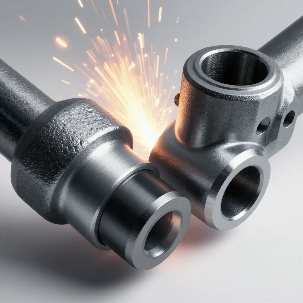
When I inspect a frame, the first place I look is the heat affected zone weakness. The Heat Affected Zone (HAZ) is the area of base metal that did not melt during welding but was heated enough to change its properties. This area often becomes more brittle than the rest of the steel. If you have a stiff weld next to a brittle HAZ, the metal cannot flex, and a crack will often trigger right at the “toe” of the weld—the point where the weld bead meets the flat steel.
- Sharp Internal Corners: Always use a radius if possible. A 90-degree inside corner is a magnet for cracks.
- Weld Toes: Look for undercut, which is a small groove melted into the base metal.
- Abrupt Changes in Thickness: Moving from a 1/2-inch plate to a 1/8-inch tube creates a natural failure point.
- Tack Welds: Small, cold tacks that were not ground out before the final pass often harbor tiny hidden cracks.
Visual Inspection and Surface Preparation
Visual inspection is the process of using the naked eye and basic tools to find surface-level defects in a metal component. It is the first and most important step in any workshop safety checklist.
You cannot find a crack through layers of grease, rust, or old paint. I start every inspection by cleaning the metal back to a shiny finish using a wire wheel or a flap disc. Once the metal is clean, I use a bright LED flashlight. Interestingly, holding the light at a low angle across the surface—rather than shining it straight down—often reveals the shadows of tiny cracks that would otherwise stay hidden.
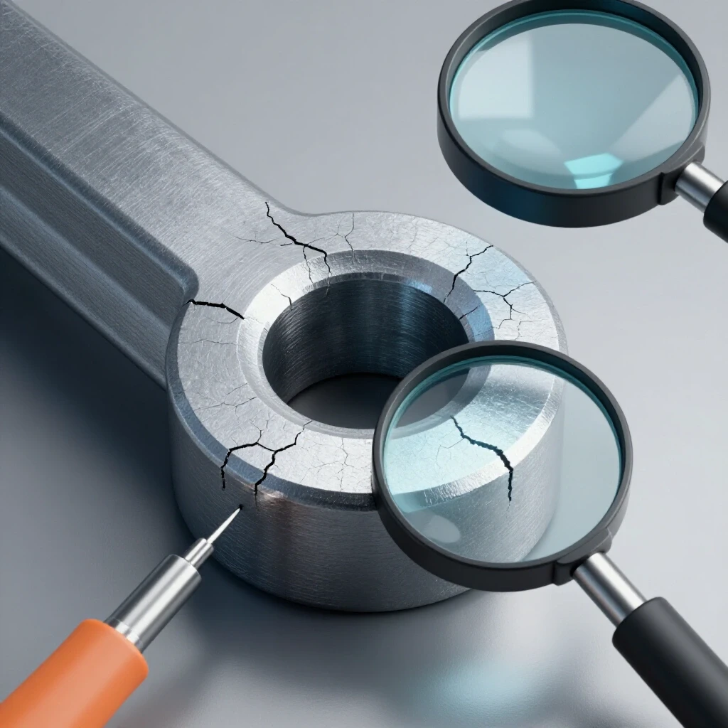
I also keep a 10x magnification loupe in my pocket. When I see a suspicious line, I zoom in. A scratch from a grinder will have a jagged, straight bottom. A structural crack usually looks like a lightning bolt, winding its way through the grain of the steel.
Using Dye-Penetrant Testing for Hidden Fractures
Dye-penetrant testing is a chemical process used to make surface-breaking cracks visible to the eye using a high-contrast colored dye. It is a highly effective, low-cost method for garage fabrication safety.
If a visual check isn’t enough, I move to a three-part dye kit. This consists of a cleaner, a red penetrant, and a white developer. It works on the principle of “capillary action,” where a liquid is pulled into a tight space.
- Clean: Spray the area with the cleaner and wipe it bone-dry. Any oil left in the crack will block the dye.
- Apply Penetrant: Spray the red dye over the area. Let it sit for 10 to 20 minutes. This “dwell time” is critical to let the dye seep into the deepest parts of the crack.
- Wipe: Gently wipe the excess red dye off the surface with a rag dampened with cleaner. Do not spray cleaner directly on the part, or you will wash the dye out of the crack.
- Develop: Spray a thin, even coat of the white developer. As it dries, it acts like a sponge, pulling the red dye out of the crack.
- Inspect: If a bright red line appears against the white powder, you have a confirmed crack.
Magnetic Particle Inspection in the Small Shop
Magnetic particle inspection involves magnetizing a steel part and applying iron powder to see where the magnetic field is broken by a crack. This method can find cracks slightly below the surface that dye might miss.
For this, I use a portable electromagnetic yoke. It looks like a heavy handle with two legs that you place on the steel. When you turn it on, it creates a magnetic field between the legs. I then dust the area with fine iron filings. If there is a crack, the magnetic field “leaks” out of the break, and the iron filings will clump together right over the crack.
This method is faster than dye because it requires less cleaning, but it only works on “ferromagnetic” materials like the mild steel and low-alloy steels we use in most structural projects. If you are checking a critical lifting point or a vehicle suspension component you’ve fabricated, this is the gold standard for peace of mind.
Mechanical Removal and Preparation for Repair
Before a crack can be fixed, it must be completely removed from the material to ensure the new weld bonds to healthy steel. Simply welding over the top of a crack is a recipe for immediate failure.
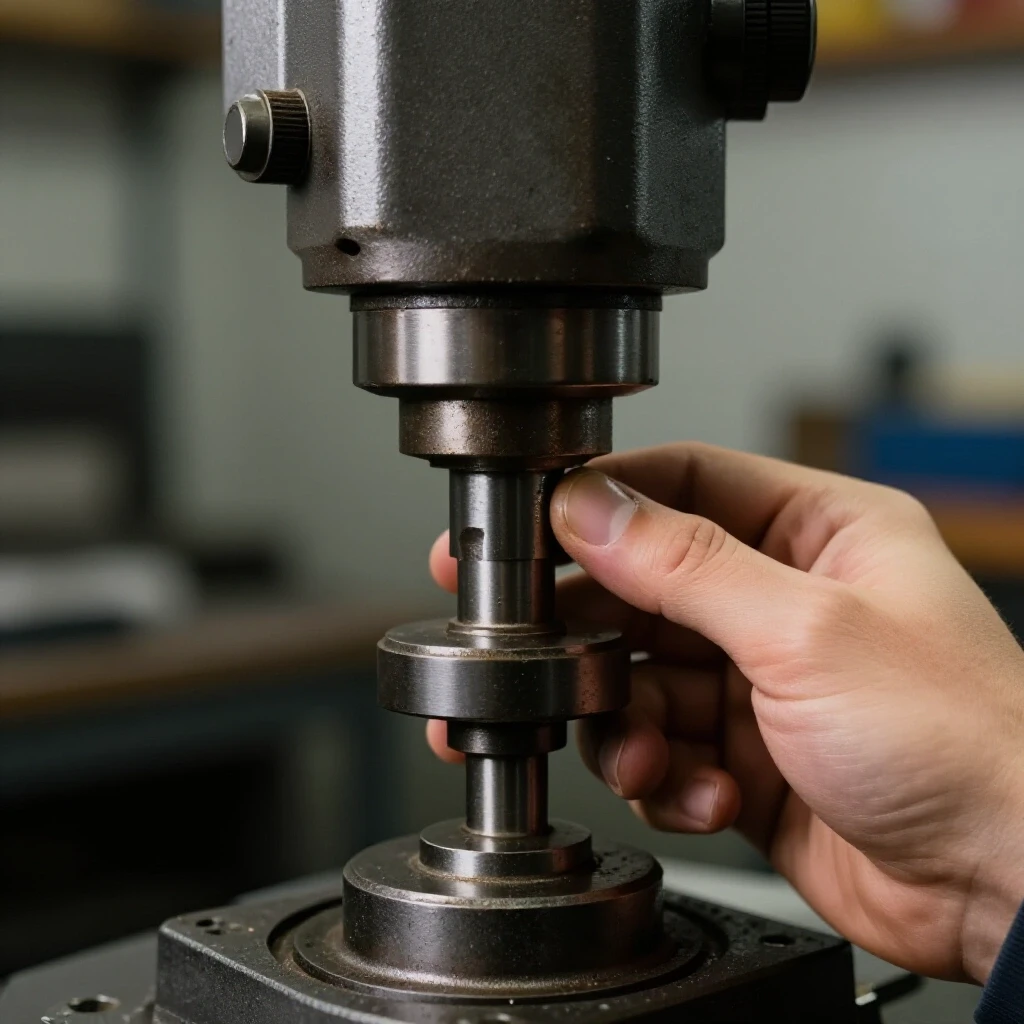
The most common mistake I see is someone “V-ing” out a crack but leaving the very ends of it intact. Cracks are like glass; they want to keep traveling. To stop this, I use a technique called “stop-drilling.” I find the very end of the crack and drill a small hole (about 1/8-inch) right through the steel. This rounds out the sharp tip of the crack and stops the stress from concentrating.
Next, I use a grinding wheel or a carbide burr to grind out the crack until it is completely gone. I don’t just make a groove; I make a wide “U” shape. A “V” shape can sometimes trap slag at the bottom, leading to welding defect troubleshooting issues later. I keep grinding until the dye-penetrant or magnetic test shows no sign of the original fracture.
| Repair Step | Tool Used | Purpose |
|---|---|---|
| Stop-Drilling | 1/8″ Drill Bit | Removes the sharp crack tip to prevent spreading |
| Gouging/Grinding | Carbide Burr or Grinding Disc | Removes the damaged metal entirely |
| Beveling | Flap Disc | Creates a 60-70 degree opening for weld penetration |
| Final Cleaning | Stainless Wire Brush | Removes oils and oxides before welding |
Rebuilding the Structural Integrity via Weld Build-up
Weld build-up is the process of filling the excavated area with new filler metal to restore the original thickness and strength of the part. This requires careful control of heat and gas coverage.
When I start the repair, I ensure my welding gas flow rate is set correctly. For most shop work using MIG or TIG, a flow of 15–20 CFH (Cubic Feet per Hour) is standard. If the flow is too low, you get porosity (tiny bubbles), which are just new cracks waiting to happen. If it’s too high, the turbulence pulls in oxygen, ruining the weld.
I always match my filler metal to the base steel. For A36 mild steel, an ER70S-6 wire is my go-to. The “70” stands for 70,000 PSI tensile strength, which is stronger than the base metal itself. I focus on getting a “full penetration” weld, meaning the new metal fuses all the way through the thickness of the plate.
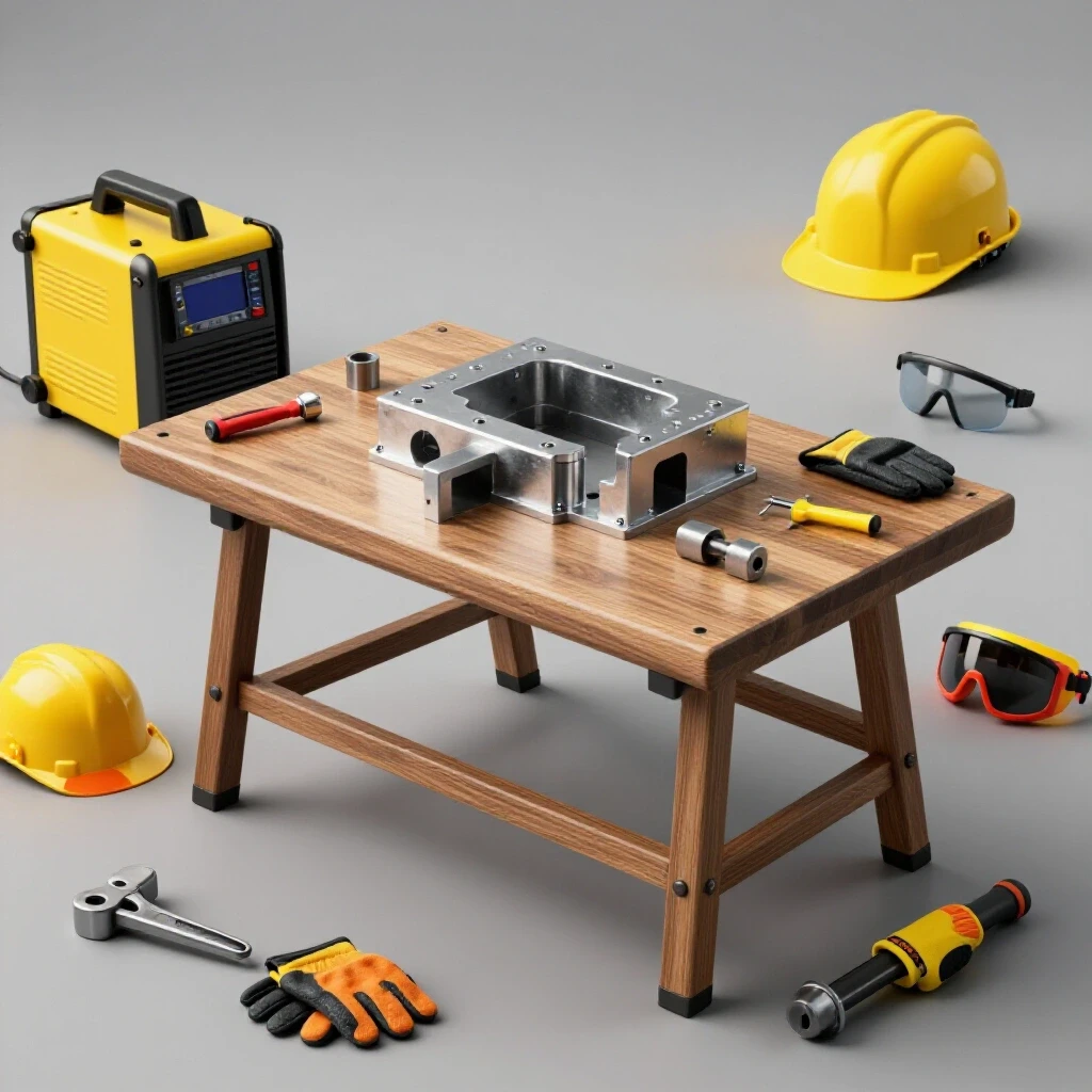
| PPE Item | Requirement | Why It Matters |
|---|---|---|
| Welding Helmet | Shade 10-13 | Protects eyes from arc flash and retina damage |
| Gloves | Top-grain Leather | Protects against UV burns and hot spatter |
| Respirator | P100 Filter | Prevents inhalation of manganese and zinc fumes |
| Clothing | Flame-Resistant (FR) | Prevents “sunburn” from the arc and fire hazards |
Post-Weld Treatments to Prevent Recurrence
Post-weld treatments are actions taken after the welding is finished to reduce internal stresses and improve the durability of the repair. This is where many hobbyists stop too early.
As a weld cools, it shrinks. This shrinkage pulls on the surrounding metal, creating “residual stress.” I often use a technique called “peening” on heavy repairs. While the weld is still warm (but not red hot), I lightly tap the weld bead with a ball-peen hammer. This compresses the metal and helps counteract the shrinking forces.
For thicker parts, I might use a propane torch to pre-heat the area to about 250°F before welding and then wrap the finished repair in a welding blanket to slow the cooling process. Cooling too fast in a cold shop can cause the metal to become brittle, leading to a new crack in the heat-affected zone.
Practical Checklist for Repair Verification
Once the repair is finished, you must prove it worked. I never trust a repair just because it looks “pretty” on the outside.
- Visual Check: Look for any “undercut” at the edges of the weld.
- Profile Check: The weld should be slightly humped (reinforced), not flat or concave.
- Re-Test: Perform another dye-penetrant test on the finished weld. Cracks can sometimes form during the cooling process.
- Clean Up: Grind the weld flush if it interferes with the part’s function, but avoid thinning the base metal.
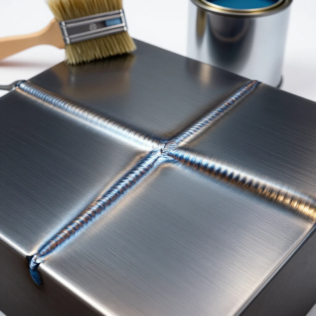
- Paint: Apply a primer and topcoat immediately. Rust is a form of surface pitting that can act as a new stress riser.
Frequently Asked Questions
Can I just weld over a crack if it’s very small? No. A crack is a physical separation in the metal. If you weld over it, the air and contaminants trapped in the crack will expand, causing porosity. Furthermore, the crack will simply continue to grow underneath your new weld, eventually breaking through again. You must grind it out completely.
What is the best way to tell a scratch from a crack? A scratch usually has a consistent depth and follows the direction of whatever made it (like a piece of sandpaper). A crack is usually irregular, zig-zags slightly, and often starts at a high-stress point like a hole or a corner. If you aren’t sure, use a dye-penetrant kit.
How do I know if the steel is too damaged to fix? If a part has “spiderweb” cracking (many cracks in different directions) or if the metal has thinned significantly from rust, it is usually better to cut out the entire section and replace it with new steel. Repairs are for localized failures, not general material degradation.
Why did my repair crack right next to the new weld? This is usually due to the heat-affected zone (HAZ) becoming brittle. This happens if you used too much heat, cooled the part too fast (like quenching it in water), or if the base metal had a high carbon content that you didn’t account for.
What shade should my welding helmet be for repair work? For most MIG and TIG repairs on steel, a shade 10 to 12 is appropriate. If you are welding at high amperages (over 200 amps), move to a shade 13 to protect your eyes from the increased infrared and UV radiation.
Does the type of welding gas matter for crack repairs? Yes. For MIG welding mild steel, a mix of 75% Argon and 25% CO2 (C25) provides a stable arc and good penetration. Using 100% CO2 is cheaper and penetrates deeper but produces more spatter and a rougher bead, which can create new stress risers.
How deep should I grind before I start welding? You should grind until you can no longer see the crack. If the metal is 1/4-inch thick, and the crack goes all the way through, you must grind a groove through the entire thickness. This ensures the new weld is a solid bridge of metal from top to bottom.
Is stop-drilling always necessary? It is highly recommended for any crack that has a “traveling” end. If the crack has already reached the edge of the plate, you don’t need to stop-drill that end. But if the crack stops in the middle of a piece of steel, drilling the tip is the only way to be sure it won’t keep growing.
Can I use a standard drill bit for stop-drilling? Yes, a high-speed steel (HSS) or cobalt drill bit is fine for mild steel. Just ensure the hole is centered exactly at the very tip of the crack. If you miss the tip, the crack will simply grow past the hole.
What is the “dwell time” in dye testing? Dwell time is the period you allow the red penetrant to sit on the metal. For steel, 10 to 20 minutes is standard. If the shop is very cold (below 50°F), you should double the dwell time because the liquid moves more slowly.
How do I avoid “undercut” during the repair? Undercut happens when you melt the base metal but don’t fill it back in with wire. To avoid this, watch the “toes” of your weld puddle. Ensure the filler metal is flowing out to the edges of the groove. Slowing down your travel speed or slightly reducing your voltage can also help.
Should I grind my repair welds flush? In many cases, leaving a small amount of reinforcement (a slight hump) makes the joint stronger. However, if the part needs to fit against another surface, or if the “toe” of the weld is very sharp, grinding it smooth can actually reduce stress concentrations. Just be careful not to grind into the base metal and make it thinner than it was originally.
(This article was written by one of our staff writers, James Harlan. Visit our Meet the Team page to learn more about the author and their expertise.)