How to Inspect Machine Tools for Critical Safety Wear (Tips)
In my 14 years on the shop floor, I have learned that a machine tool is a living system of forces. When you are standing in front of a manual lathe or a vertical mill, you aren’t just cutting metal; you are managing a high-energy environment where structural integrity matters as much as the final dimensions of your part. I remember a specific afternoon early in my career when a colleague was turning a heavy piece of 4140 steel. He hadn’t noticed the subtle “play” in the tailstock. As the cutting tool engaged, the workpiece shifted just a few thousandths of an inch, caught the tool, and threw the part across the room. It was a stark reminder that mechanical wear is not just a maintenance issue; it is a safety crisis waiting to happen.
For those of us working in home shops or small fabrication hubs, the anxiety often stems from the unknown. We worry about structural metal load capacity or whether a joint will hold under pressure. However, many of these failures begin long before the welder is even sparked. They start at the machine. If your equipment has hidden mechanical fatigue, your joint preparation will be off, your tolerances will fail, and your final assembly will inherit those weaknesses. Understanding how to spot these physical failures in your equipment is the first step toward building projects that last.
Identifying Mechanical Fatigue in Manual Workshop Equipment
Mechanical fatigue refers to the weakening of a material caused by repeatedly applied loads. In a workshop setting, this manifests as physical degradation in the parts of a machine that move against one another or hold heavy weight. When these components wear down, they lose their ability to resist the forces of cutting, leading to unpredictable tool behavior.
In my experience, the most dangerous failures are those you cannot hear until it is too late. We often focus on the motor, but the real risks live in the “ways,” the “gibs,” and the “spindles.” These are the structural foundations of the machine. If these components are compromised, the machine can no longer provide a stable platform. This instability leads to “chatter,” which is a high-frequency vibration that can shatter carbide tools or, worse, cause a workpiece to eject from the machine.
| Component | Type of Wear | Primary Safety Risk |
|---|---|---|
| Machine Ways | Scoring/Pitting | Unpredictable carriage movement and tool “dig-in.” |
| Spindle Bearings | Excessive Play | Workpiece ejection or catastrophic tool shattering. |
| Chuck Jaws | Bell-mouthing | Loss of grip on the workpiece at high RPM. |
| Gib Strips | Loose fit/Slop | Structural misalignment during heavy cuts. |
| Lead Screws | Backlash | Sudden “climb” into the material, causing breakage. |
Why Machine Stability Affects Structural Metal Load Capacity
The relationship between your machine’s health and your project’s safety is direct. If you are preparing a bevel for a structural weld on A36 steel (which has a yield strength of about 36,000 PSI), that bevel must be uniform. If your machine ways are worn, the tool will “dip” or “climb,” creating an uneven Heat Affected Zone (HAZ). The HAZ is the area of base metal that has had its microstructure and properties altered by welding heat. An uneven joint leads to uneven heat distribution, which can cause the HAZ to become a brittle failure point when the structure is put under load.
Evaluating Lathe Bed and Way Integrity for Safe Operation
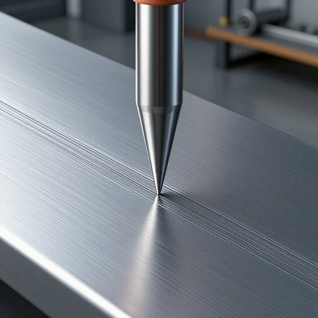
The “ways” of a machine are the precision-ground surfaces upon which the moving parts, like the carriage or tailstock, slide. Think of them as the tracks of a railroad. If the tracks are warped or gouged, the train cannot stay stable. In fabrication, “scoring” occurs when metal chips get trapped under the sliding surfaces and grind into the metal, creating deep scratches.
To inspect these, I always start with a clean, dry surface. Run your fingernail across the ways. If you feel ridges or “pitting,” the machine is no longer providing a flat reference plane. This is critical because a carriage that “rocks” as it moves will change the angle of the tool. In a structural project, this means your dimensions will drift, and your bolt holes or mating surfaces will not align. Forced alignment in assembly introduces “pre-stress,” which consumes your safety margin before the structure even carries a load.
Detecting Hidden “Sway” in the Bed
- Move the carriage to the far end of the bed and attempt to physically rock it by hand.
- Listen for a “clink” or “thud,” which indicates the hold-down plates are loose or the ways are thinned.
- Look for “shining” spots, which indicate localized high-wear areas where the geometry has changed.
Detecting Spindle Play and Bearing Wear to Prevent Tool Failure
The spindle is the heart of any rotating machine. It is the shaft that holds the chuck or the milling cutter. Spindle “runout” is the measurement of how much the spindle deviates from a perfect circle as it rotates. If a spindle has too much “play” or “slop,” the bearings that support it are likely failing.
I once inspected a mill where the operator complained of poor surface finishes. Upon checking the spindle, we found nearly 0.005 inches of movement. While that sounds small, at 2,000 RPM, that movement creates a massive centrifugal force. This vibration can lead to “brittle fracture” in the cutting tool. Brittle fracture is a sudden failure where the material breaks without prior deformation. When a tool shatters, the fragments move at speeds that can penetrate standard safety glasses.
The Hand-Force Test for Bearings
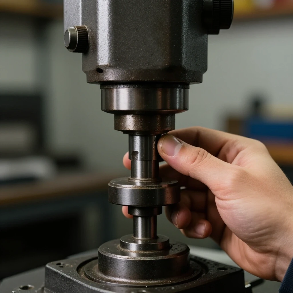
Without using any power, grasp the spindle or the mounted chuck and try to move it up, down, and side-to-side. You should feel zero movement. If you feel a “clunk,” the bearing races are likely worn. This wear changes the “load shear path,” or the direction in which forces travel through the machine. When the load path is compromised, the machine can no longer safely absorb the energy of a heavy cut.
Assessing Workholding Security: Chuck and Vise Wear Patterns
Workholding refers to the devices, like chucks and vises, that keep your material from moving. This is arguably the most critical safety interface in the shop. “Bell-mouthing” is a common wear pattern in lathe chucks where the jaws become worn at the front, causing them to grip the material only at the back.
This creates a pivot point. Under the pressure of a drill or a turning tool, the material can “cam out” of the jaws. For someone building a heavy frame or a structural component, a part that moves in the vise during a critical cut will have inaccurate geometry. If you are welding a joint that was machined in a loose vise, the gap will be inconsistent. Inconsistent gaps lead to “shielding gas porosity,” where the protective gas (usually flowing at 15–20 CFH) cannot reach the root of the weld, leaving tiny holes that weaken the joint.
Visual Cues of Workholding Failure
- Jaw Serrations: Look for flattened or “rolled” teeth on the chuck jaws. If the teeth are smooth, they cannot bite into the metal.
- Vise Parallelism: Use a simple square to see if the vise jaws are still vertical. A vise that “lifts” when tightened will tilt your workpiece.
- Cracked Castings: Inspect the body of the chuck or vise for hairline fractures. These are signs of “over-torquing,” which can lead to a catastrophic burst under load.
Managing Backlash and Gib Tension for Structural Precision
“Backlash” is the “dead space” or play in a lead screw when you change directions. While some backlash is normal in manual machines, excessive backlash (more than 0.015 inches) is dangerous. It allows the table or carriage to be “pulled” into the tool by the force of the cut. This is known as “climb cutting” in a mill, and if the machine isn’t tight, it can rip the workpiece out of the vise.
“Gibs” are adjustable metal strips used to take up the wear between sliding parts. If the gibs are too loose, the machine “chatters.” If they are too tight, you lose the “feel” of the cut, making it easy to overload the tool. For a fabricator, managing this tension is about ensuring the machine stays where you put it.
Adjusting for Safety Margins
When I set up a machine for a heavy structural cut, I always check the gibs first. I aim for a “firm but smooth” movement. This ensures that the machine can handle a 2:1 or even a 4:1 safety factor. A safety factor is the ratio of a system’s absolute strength to its intended load. If your machine is sloppy, your safety factor drops because the machine might move unexpectedly, causing a “stress riser” in your material. A stress riser is a sharp change in geometry (like a gouge) that concentrates force and leads to cracking.
PPE Integration and Workshop Safety Protocols
No matter how well you inspect your machine, you must protect yourself from the variables you cannot control. Garage fabrication safety starts with the right gear. When machining, your primary concern is high-velocity chips and potential tool breakage.
When you transition from machining to welding those components, your safety needs change. You move from impact protection to radiation and thermal protection. For example, while a clear face shield is great for the lathe, you need a welding helmet with a Shade 10-13 filter for structural welding to prevent “arc eye.”
The Essential Safety Kit for Machine Inspection
- High-Intensity Flashlight: To see scoring in the dark recesses of the machine bed.
- Feeler Gauges: To measure the gap between gibs and ways.
- Safety Glasses (Z87+ Rated): Essential even during inspection to protect against spring-loaded parts or pressurized oil.
- Non-Contact Thermometer: To check for overheating bearings after a short run.
A Practical Workshop Safety Checklist for Equipment Maintenance
To keep your shop running safely, you need a repeatable process. I use a simple “Look, Feel, Listen” framework before I start any major project. This prevents the “structural design uncertainty” that haunts many intermediate fabricators. If you know your machine is true, you can trust your parts.
Pre-Project Inspection Checklist
- Clean the Ways: Remove all chips and old oil. Look for new scratches.
- Check Lubrication: Ensure all oil ports are clear. Metal-on-metal contact without oil causes rapid “galling” (a form of wear caused by adhesion).
- Test Spindle Runout: Rotate the spindle by hand. Feel for any “grittiness” or resistance.
- Verify Workholding: Tighten the chuck or vise on a scrap piece. Try to move the scrap with a pry bar (using light pressure) to ensure it is locked.
- Audit the Lead Screws: Measure the backlash on all axes using the handwheel dials.
Why Joint Preparation and Machine Health Prevent Structural Cracking
Structural cracking often starts at the microscopic level. If your machine is vibrating (chattering) while you are squaring up a piece of tube steel, it leaves “micro-grooves” on the surface. When you weld this piece, those grooves can trap contaminants or create “stress concentrations.”
In my years of inspecting industrial steel, I have seen many welds fail not because the welder was bad, but because the “fit-up” was poor. A gap that is too wide forces the welder to “bridge” the distance, often leading to “lack of fusion” at the root. Lack of fusion is a welding defect where the weld metal does not properly combine with the base metal. This creates a hidden void inside the joint. Under a load, this void acts like a perforated line on a piece of paper—it is exactly where the metal will tear.
Understanding Load Paths in Fabricated Structures
When you build a bracket or a frame, you must imagine the “load path.” This is the route the force takes from the point of impact through the structure to the ground. If your machine tools are worn, your holes might be slightly “oblong” or your surfaces “out of square.” This forces the load path to “bend” around these inaccuracies.
Every time a load path bends, it creates “shear stress.” Shear stress is a force that tends to slide internal layers of material past each other. If your machine-worn parts cause a 5-degree misalignment in a structural column, the shear stress on your bolts or welds can increase by 20% or more. This is why “diagnostic inspection” of your tools is the foundation of structural safety.
Conclusion: Taking the Next Steps in Shop Safety
Maintaining a safe workshop is a continuous process of observation. You don’t need expensive sensors to tell you a machine is wearing out; you just need to pay attention to the feedback the metal gives you. The “feel” of a handwheel, the sound of a cut, and the finish on a part are all data points.
By implementing these routine checks, you move from “guessing” to “knowing.” You reduce the risk of structural failure and increase the predictability of your material performance. Start today by cleaning your machine bed and performing the “hand-force test” on your spindle. These small actions are the safety margins that protect you and your work.
Frequently Asked Questions
What is the most dangerous sign of wear on a manual lathe?
The most dangerous sign is “spindle play.” If you can feel the spindle move within its housing, the bearings are failing. This can lead to the chuck and workpiece vibrating loose or the tool digging into the work and causing a catastrophic ejection of the part.
How much backlash is “too much” for a hobbyist machine?
While “too much” can vary, generally, anything over 0.015 to 0.020 inches on a lead screw should be addressed. Excessive backlash makes “climb milling” dangerous and can lead to the machine “jumping” into the cut, which often breaks the tool or ruins the workpiece.
Can I still use a machine with “scored” ways?
You can, but with caution. Scoring means the machine is no longer perfectly accurate. You should avoid doing precision structural work in the area of the scoring. For safety, ensure the scoring hasn’t created a “burr” that could catch the carriage and cause it to stutter or jump during a cut.
Why does my machine vibrate even when the tools are sharp?
This is usually “chatter,” caused by a lack of rigidity. Check your gibs; they are likely too loose. When gibs are loose, the sliding components of the machine can “bounce” under the pressure of the cut. This vibration can lead to brittle fracture in your tools.
What is “bell-mouthing” in a chuck, and why is it a safety risk?
Bell-mouthing happens when the front of the chuck jaws wears down more than the back. This means the jaws only touch the workpiece at a single point rather than along their full length. Under load, the part can act like a lever and pop out of the chuck.
How do I check if my machine vise is still safe to use?
Check for “jaw lift.” Put a piece of scrap in the vise and tighten it. If the workpiece moves upward as you tighten, the vise is worn. Also, look for cracks in the cast iron body, especially around the bolt holes, which indicate the metal is fatigued.
Does machine wear affect my welding quality?
Yes. If your machine tools produce inaccurate joints or poor surface finishes, your “fit-up” will be poor. This leads to inconsistent weld gaps, which can cause “lack of fusion” or “porosity,” both of which significantly weaken the structural integrity of your project.
What should I do if I find a crack in a machine component?
Stop using the machine immediately. Cracks in structural components like the headstock, carriage, or vise are “critical failure points.” Under the stress of operation, these cracks can propagate (grow) instantly, leading to a total mechanical collapse.
How often should I perform a safety inspection on my tools?
I recommend a “quick check” before every session and a “deep dive” inspection every 20-40 hours of run time. If you are starting a project that involves heavy structural loads, always perform a full inspection first to ensure your “load shear paths” are secure.
What is the difference between “runout” and “play”?
“Runout” is how much a part wobbles as it spins (measured with a dial indicator). “Play” is how much you can physically move a part by hand when it is sitting still. Both are indicators of wear, but “play” usually points to failing bearings or loose gibs.
(This article was written by one of our staff writers, James Harlan. Visit our Meet the Team page to learn more about the author and their expertise.)