How to Avoid Design Errors in Sheet Metal Bending (Guide)
In my fourteen years on the shop floor, I have seen more parts end up in the scrap bin because of poor planning than because of poor craftsmanship. I remember an early project where I was tasked with creating a series of structural brackets for a heavy equipment frame. I had the dimensions right, the material was high-grade steel, and my measurements were spot on. However, when the press brake hit the metal, the outside of the bend didn’t just stretch—it fractured. That failure was a turning point for me. It taught me that metal isn’t just a solid block; it is a living arrangement of grains and stresses that reacts to every force we apply.
When you work with sheet metal, you are essentially forcing a flat plane to become a three-dimensional object. This process introduces massive amounts of internal stress. If your design doesn’t account for how the metal moves, the part will fail. Whether you are a hobbyist building a custom chassis or an intermediate fabricator working on a structural assembly, understanding the physics of the bend is the only way to ensure your projects are safe and reliable.
Understanding Material Stress and Yield Thresholds
Material stress is the internal force that resists deformation, while the yield threshold is the point where the metal permanently changes shape. In sheet metal work, we must exceed the yield point to create a bend, but we must stay below the ultimate tensile strength to prevent the metal from tearing apart.
When I analyze a design, I start with the material properties. Every alloy has a specific yield strength, which is the amount of pressure it can take before it stops “springing back” to its original shape. If you try to bend a material that is too brittle or has a high yield strength without a proper radius, you will create micro-fractures. These cracks might be invisible to the naked eye, but they act as stress risers. Over time, vibration or weight will cause these cracks to grow, leading to a sudden structural failure.
The Role of Ductility in Successful Forming
Ductility is the ability of a metal to undergo significant plastic deformation before it actually breaks. It is the quality that allows us to stretch the outer “skin” of a bend without it snapping like a dry twig.
Think of ductility as the “stretchiness” of the steel. Materials like soft aluminum (3003-H14) are highly ductile and very forgiving during the forming process. In contrast, high-strength steels or T6-tempered aluminum are much stiffer. If your design calls for a sharp corner in a low-ductility material, you are asking for trouble. I always check the elongation percentage in material data sheets; if that number is low, I know I need to be much more careful with my geometry.
The Critical Importance of Minimum Bend Radii
The bend radius is the measurement of the inside curve of a formed part. It is perhaps the most important variable in your design because it dictates how much the material on the outside of the curve must stretch to accommodate the turn.
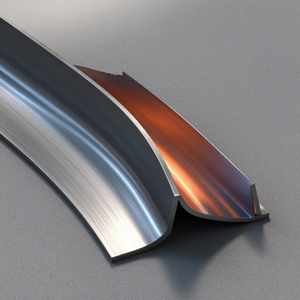
If the inside radius is too small—what we often call a “sharp bend”—the material on the outside is stretched beyond its physical limits. This is where most fabrication failures begin. I have seen brackets that looked perfect on the outside but had deep, hidden cracks along the bend line because the designer insisted on a tight corner. As a rule of thumb, I never design a part with an inside radius smaller than the thickness of the material (1t), though for many alloys, 2t or even 3t is a much safer margin.
Calculating the Ideal Radius for Different Alloys
Different metals require different radius considerations based on their thickness and temper. A design that works for 16-gauge mild steel will fail miserably if applied to 16-gauge stainless steel or 6061-T6 aluminum.
Stainless steel, for example, work-hardens very quickly. This means the more you deform it, the harder and more brittle it becomes during the process. If your radius is too tight, the material becomes so hard that it simply snaps. Below is a reference for common materials I use in the shop to ensure I stay within safe structural limits.
| Material Type | Recommended Min Radius (Relative to Thickness ‘t’) | Common Failure Mode |
|---|---|---|
| Mild Steel (A36/1018) | 1.0t | Slight orange-peeling |
| Aluminum 5052-H32 | 1.5t | Cracking on outer edge |
| Aluminum 6061-T6 | 3.0t – 4.0t | Sudden brittle fracture |
| Stainless Steel 304 | 2.0t | Work-hardening and snapping |
| Cold Rolled Steel | 1.0t | Surface crazing |
How Grain Orientation Affects Structural Integrity
Metal is formed by rolling it through heavy machinery, which creates a “grain” similar to the grain in a piece of wood. This grain consists of elongated crystals that run in the direction the metal was rolled at the mill.
When you design a part, you must consider which way these grains are running. If you bend the metal “with the grain” (parallel to it), the material is much more likely to crack. It is like trying to fold a piece of wood along its grain—it splits. Bending “across the grain” (perpendicular to it) allows the metal to stretch more evenly, resulting in a much stronger and more reliable joint. I always mark the grain direction on my sheets before I even start my layout to avoid this simple but costly error.
Strategies for Multi-Directional Bending
In complex designs where you have bends running in multiple directions, you cannot always bend everything across the grain. This is a common hurdle in custom fabrication.
In these cases, I look for a “diagonal” compromise. By rotating the part layout 45 degrees relative to the grain, you ensure that no single bend is perfectly parallel to the grain. This distributes the stress more effectively across the internal structure of the metal. While it might result in more material waste during the cutting phase, the increase in structural reliability is well worth the extra few square inches of scrap.
Mastering Bend Allowance and the K-Factor
When you bend a piece of metal, the inside of the bend compresses and the outside stretches. Somewhere in the middle, there is a “neutral axis” that stays exactly the same length.
The K-factor is the ratio that describes where this neutral axis is located within the thickness of the material. If you don’t account for this, your finished part will be either too long or too short. For most standard bends, the K-factor is roughly 0.44 to 0.45. This means the neutral axis is about 45% of the way through the material from the inside. Calculating your bend allowance correctly ensures that holes, notches, and flanges end up exactly where they need to be for a safe assembly.
The Formula for Real-World Accuracy
To find the actual length of the material you need (the “flat pattern”), you must calculate the Bend Allowance (BA). This is the length of the arc along the neutral axis.
The formula I use is: BA = Angle × (π / 180) × (Radius + (K-factor × Thickness)). This might look like high school geometry, but it is the difference between a part that fits and a part that has to be hammered into place. Hammering a part into place introduces “preload” stress, which can lead to premature fatigue. I always verify my K-factor by doing a test bend on a scrap piece of the exact same material and thickness before I commit to a final design.
Preventing Deformation Near Holes and Flanges
One of the most frequent mistakes I see in design is placing holes or cutouts too close to a bend line. When the metal is formed, the area around the bend “flows,” and any nearby features will be pulled out of shape.
If a hole is too close to the bend, it will stretch into an oval shape. This isn’t just an aesthetic problem; it ruins the mechanical fit of bolts and pins, and it creates a weak point where the material is thin. I follow a strict rule: the edge of any hole must be at least two times the material thickness plus the bend radius away from the bend line. This ensures the hole stays in the “dead zone” of the metal where no stretching occurs.
Minimum Flange Length Requirements
A flange is the part of the metal that is being bent. If the flange is too short, the tool in the shop won’t be able to grip it properly, leading to a distorted, uneven, or unsafe bend.
I have seen many designs where a fabricator tries to create a tiny 1/4-inch flange on 1/8-inch plate. It rarely works. A good guideline is to make sure your flange length is at least four times the material thickness. This gives the forming tools enough surface area to apply pressure evenly. If your design requires a very small flange, it is often better to design it longer and then trim it back after the bend is complete.
Managing Springback in Structural Design
Springback is the tendency of metal to partially return to its original shape after the bending pressure is released. This happens because the material near the neutral axis was only stressed elastically, not plastically.
Every material has a different springback rate. High-strength alloys might spring back as much as 5 to 10 degrees, while soft copper might only move half a degree. If your design requires a perfect 90-degree angle for structural stability, you have to account for this. In the design phase, I don’t just think about the final shape; I think about the “overbend” required to get there. If you ignore springback, your parts won’t square up, and you’ll end up with gaps in your assembly that compromise its strength.
Factors That Influence Springback
- Material Hardness: Harder materials have more “memory” and will spring back further than annealed or soft materials.
- Bend Radius: A larger radius usually results in more springback because a larger volume of material is held in the elastic zone.
- Thickness: Thinner materials tend to have more proportional springback than thicker plates.
- Tooling: While we aren’t discussing machine setup, the designer should know that air-bending (where the metal only touches three points) results in more springback than “bottoming” the die.
A Checklist for Validating Your Design
Before I ever move a design from the screen to the shop floor, I run through a verification checklist. This helps me catch those small errors that turn into big failures once the metal starts moving.
- Check the Radius: Is the inside radius at least 1t for mild steel or 3t for high-strength aluminum?
- Verify Grain Direction: Have I noted the rolling direction and oriented the most critical bends perpendicular to it?
- Hole Clearance: Are all holes located at a safe distance (2t + R) from the bend lines?
- Flange Height: Are all flanges at least 4t in height to ensure proper forming?
- K-Factor Accuracy: Did I use the correct K-factor for this specific material and thickness?
- Material Substitution: If I planned for mild steel but ended up using stainless, have I adjusted the radius and bend allowance?
Conclusion
Mastering the nuances of metal forming is a journey of respecting the physical limits of your materials. In my years of inspecting failures, I have learned that a “perfect” project is rarely the result of luck. It is the result of a designer who understood that every bend is a trade-off between geometry and stress. By choosing the right radius, respecting the grain, and calculating your allowances with precision, you create structures that aren’t just shaped like they should be—they are built to last. Take the time to do the math and test your scrap; the reliability of your final project depends on those few extra minutes of preparation.
Frequently Asked Questions
What is the “neutral axis” in sheet metal bending? The neutral axis is an imaginary line within the thickness of the sheet metal that neither stretches nor compresses during the bending process. Its length remains constant. Designers use the K-factor to locate this axis, which is essential for calculating the correct flat length of a part before it is formed.
Why did my aluminum bracket crack even though I used a large radius? Cracking in aluminum often occurs because of the material’s temper or grain direction. If you used 6061-T6, it is a “T6” heat-treated alloy that is quite brittle. If you also bent it parallel to the rolling grain, the combination of a brittle temper and poor orientation can cause failure even with a decent radius.
How do I find the grain direction on a sheet of metal? On many sheets, you can see faint longitudinal lines or “brush strokes” from the rolling process. If the sheet is covered in a protective film, the manufacturer often prints text or arrows in the direction of the grain. If you are unsure, a light sanding can often reveal the grain’s orientation.
What happens if I ignore the K-factor in my design? If you ignore the K-factor, your final part dimensions will be inaccurate. Because the metal stretches on the outside of the bend, your part will usually end up longer than you intended. This leads to misalignment in bolt holes and gaps in structural assemblies, which can weaken the overall build.
Can I bend a flange that is shorter than the recommended 4t? It is physically possible, but it is risky. A short flange may not span the opening of the bottom die on a press brake, causing it to slip or “wipe” rather than bend cleanly. This results in a distorted radius and a flange that is not square, compromising the structural integrity of the joint.
What is “orange-peeling” on a bend? Orange-peeling is a grainy, textured appearance on the outside of a bend. It is a sign that the material has been stretched near its limit. While not always a total failure, it indicates significant stress and suggests that a larger bend radius should be used to maintain the material’s strength.
Is it better to use a larger radius than necessary? Generally, yes. A larger radius reduces the stress on the outer fibers of the metal and decreases the risk of cracking. The only downside is that a larger radius can increase springback and might interfere with the fit of other components if your tolerances are very tight.
How does thickness affect the bend radius? As material gets thicker, the distance from the neutral axis to the outer edge increases. This means the outer surface must stretch much further to complete the same 90-degree turn. Consequently, thicker materials require larger minimum bend radii to prevent the surface from tearing.
Why does stainless steel feel harder to bend than mild steel? Stainless steel has a high work-hardening rate. As the metal is deformed, its molecular structure changes and becomes significantly harder. This requires more force to form and makes the material more prone to snapping if the design doesn’t allow for a generous bend radius.
Should I design my parts with a 0.5 K-factor for simplicity? While 0.5 is a common “middle of the road” guess, it is rarely accurate. Most metals have a K-factor between 0.33 and 0.45. Using 0.5 will almost always result in a part that is slightly too long. For precision structural work, using a verified K-factor from a material table is always the safer choice.
(This article was written by one of our staff writers, James Harlan. Visit our Meet the Team page to learn more about the author and their expertise.)