How to Keep Project Logs for Custom Fabrications (DIY Guide)
I have spent eighteen years in industrial fabrication mills and custom shops, and I have learned one hard truth. Most shop problems are not solved by a flash of genius. They are solved by the tedious, disciplined act of writing things down. When a spindle starts screaming at 3,000 RPM or a TIG weld on 4130 tubing starts bubbling with porosity, the frustration is real. You want to fix it now, but random guessing usually leads to wasted material and more downtime.
In my early years, I once spent three days chasing a mysterious vibration in a large-scale milling setup. I adjusted the leveling feet, swapped the end mills, and even messed with the VFD settings. Nothing worked. It was only when I looked back at a scrap piece of paper where I had noted the material batch number that I realized the “mild steel” was actually a much harder alloy. My feeds and speeds were correct for A36, but the material was something else entirely. Since then, I have treated my shop notes as my most important tool.

A systematic approach to recording your build process allows you to isolate variables. If you do not know what your settings were yesterday when the machine was running perfectly, you cannot possibly know what changed today. This guide focuses on how to build a diagnostic history for your projects so you can stop guessing and start fixing.
Building a Diagnostic Framework for Workshop Processes
A diagnostic framework is a structured method of recording baseline conditions, material specifications, and machine parameters throughout a build. This creates a historical map that allows a fabricator to identify exactly when a process deviated from the norm, making it easier to isolate mechanical or metallurgical failures.
When I start a custom build, I do not just write down the dimensions. I record the “health” of the machine. This includes checking the backlash in the lead screws and the temperature of the shop. Metal expands and contracts with heat. If you are aiming for a tolerance of 0.002 inches on a lathe, a ten-degree shift in shop temperature can throw your measurements off. By logging these environmentals, you create a baseline.
I recommend starting every project with a “State of the Shop” entry. Note the ambient temperature, the humidity, and the specific machine you are using. If you have multiple welders or lathes, each one has its own personality. A setting that works on one might not work on another due to internal wear or different circuit loads. This initial step prevents you from chasing “ghosts” that are actually just environmental changes.
Isolating Variables in Custom Metalwork
Variable isolation is the practice of changing only one factor at a time while keeping all other conditions constant to identify the cause of a problem. In a shop environment, this means documenting every adjustment to gas flow, amperage, or spindle speed to see which specific change resolves an error.
I recall a project involving a series of stainless steel tanks where the welds suddenly began showing signs of oxidation. Instead of changing the tungsten, the gas, and the filler rod all at once, I used my log to track one change at a time. I recorded the gas flow at 20 CFH, then moved it to 25 CFH and noted the result. By keeping a strict record, I found the culprit: a tiny crack in the gas lens that was only visible under magnification.
- Step 1: Identify the failure (e.g., weld porosity or tool chatter).
- Step 2: List all possible causes based on your current setup.
- Step 3: Change one setting and record the new value.
- Step 4: Test the result and document the observation.
- Step 5: Repeat until the issue is resolved.
Tracking Material Specifications and Metallurgical Data
Tracking material data involves noting the specific alloy, temper, and heat numbers of the metal used in a project. This information is vital because subtle differences in chemical composition can change how a material reacts to welding heat, cutting forces, or heat treatment.
Not all steel is created equal. Even within the same grade, like 6061 aluminum, different batches can behave differently under a tool. I always record the source of my material and any markings on the stock. If I encounter cracking during a bend, I can look at my notes and see if that specific batch of metal came from a different supplier.
Why Material Grades Affect Diagnostic Paths
Understanding the specific properties of your material allows you to predict how it will respond to stress and heat. When you log the material grade, you are essentially recording the “rules” the metal must follow, which helps you spot when a machine or process is violating those rules.
If you are troubleshooting weld porosity, the material log is your first stop. Is the metal oily? Did it come from a cold rack where condensation could form in the pores? I once had a client whose welds were failing inspection due to hydrogen embrittlement. By checking the log, we found the material had been stored in a high-humidity area without being wiped down with acetone. The log saved us from rebuilding the entire machine.
| Material Feature | Diagnostic Importance | Logged Metric |
|---|---|---|
| Alloy Grade | Determines melting point and hardness | AISI/ASTM Number |
| Surface Finish | Affects weld arc stability and tool wear | Mill Scale, Polished, or Oily |
| Material Thickness | Dictates amperage and feed rates | Decimal Inches (e.g., 0.250″) |
| Batch/Heat Number | Identifies consistency across the project | Supplier Tag Number |
Troubleshooting Weld Porosity Through Parameter Logging
Weld porosity consists of small gas pockets trapped in the weld metal, often appearing as tiny holes or “Swiss cheese” on the surface. By logging shielding gas flow, electrode type, and travel speed, you can systematically eliminate contamination sources or improper settings.
When I see porosity, I do not just turn up the gas. I look at my log to see what the flow rate was when the welds were clean. If I was at 20 CFH yesterday and it worked, but today it does not, the problem is likely not the flow rate itself. It might be a draft in the shop or a leak in the hose.
Mapping Gas Flow and Arc Stability
Recording your welding parameters helps you find the “sweet spot” for your specific machine and environment. This includes tracking the voltage, wire feed speed (WFS), and the specific type of shielding gas, such as a 75/25 Argon/CO2 mix for MIG welding.
I suggest keeping a small notebook at the welding station. For every major joint, write down your settings. If the arc feels “unstable” or you notice “magnetic arc blow”—where the arc wanders due to magnetic fields—note the position of your ground clamp. Moving the ground is a common fix for arc blow, and logging the clamp position helps you avoid the problem on future similar geometries.
- Shielding Gas Flow: Measure in Cubic Feet per Hour (CFH).
- Voltage/Amperage: Record the actual display reading during the weld.
- Electrode Extension: Note the “stick-out” distance (usually 3/8″ to 1/2″).
- Travel Speed: Estimate in Inches Per Minute (IPM).
Eliminating Tool Chatter and Spindle Play with Maintenance Records
Tool chatter is a high-frequency vibration that occurs when the cutting tool and the workpiece are not perfectly rigid, resulting in a poor surface finish. Tracking spindle runout, gib tightness, and tool-holding methods in a log helps you identify if the vibration is caused by mechanical wear or incorrect cutting data.
Nothing ruins a part faster than chatter. It sounds like a scream and leaves a finish that looks like a washboard. In my experience, chatter is often a “harmonic” issue. This means the tool is vibrating at a frequency that matches the machine’s natural resonance. By logging the RPM where chatter occurs, you can find “stable” speeds.
Identifying Rigid Harmonic Vibrations
Harmonic vibrations are patterns of movement that occur at specific frequencies. In metalworking, recording the exact RPM and feed rate where chatter begins allows you to calculate a “feed-per-tooth” that moves the vibration out of the audible and physical range of the machine.
If I am milling a pocket and chatter starts at 2,500 RPM, I record that. I then try 2,200 RPM or 2,800 RPM. I also check the “backlash”—the amount of play in the lead screws. If my log shows that backlash has increased from 0.001 inches to 0.005 inches over a month, I know it is time to tighten the gibs or replace the lead screw nut.
- Check Spindle Runout: Use a dial indicator to measure the wobble. A healthy spindle should be under 0.0005 inches.
- Measure Backlash: Turn the handwheel and see how far it moves before the table shifts.
- Log Tool Stick-out: The further the tool hangs out of the holder, the more likely it is to vibrate.
- Calculate Chip Load: Use the formula: Feed Rate / (RPM x Number of Flutes). Target a specific “Inches Per Tooth” (IPT) based on the material.
Diagnosing Machine Electronics and Motor Controller Faults
Electrical troubleshooting involves measuring the flow of electricity through a machine’s components to find interruptions or failures. Keeping a log of standard voltage and resistance values for your motors and controllers allows you to identify anomalies like back-EMF or phase imbalances.
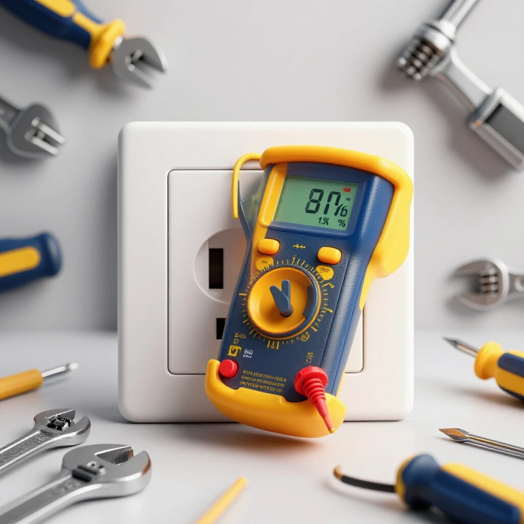
Modern fabrication equipment relies heavily on electronics. When a CNC mill or a wire feeder stops working, it is often an electrical “gremlin.” These are intermittent issues that are hard to find. I use a multimeter to check the resistance (Ohms) of motor windings when the machine is new. I write these numbers down in the back of the manual.
Documenting Resistance and Voltage Drops
Voltage drop is the decrease in electrical potential as current flows through a circuit, often caused by poor connections or long wire runs. By logging the voltage at the wall and the voltage at the motor under load, you can determine if your shop’s wiring is sufficient for the machine.
If a motor is running hot, I check the “current phase unbalance.” In a three-phase motor, the current in each leg should be nearly identical. If one leg is drawing 10% more than the others, the motor will vibrate and eventually burn out. I log these readings every six months as part of a preventative maintenance routine.
- Input Voltage: Check for a steady 220V or 110V.
- Motor Resistance: Measure Ohms across the windings.
- Continuity: Ensure there are no breaks in the ground wires.
- Heat Tracking: Use an infrared thermometer to log the temperature of the motor casing after an hour of use.
Actionable Tracking Frameworks for the Shop
A tracking framework is a standardized template or checklist used to record data consistently across different projects. These frameworks ensure that you do not forget to check critical variables like alignment, lubrication, or fastener torque during a complex build.
I have found that having a physical “check-sheet” clipped to the machine is better than relying on memory. When you are in the middle of a difficult weld or a precise machining pass, your brain is focused on the task, not the data. A pre-made template forces you to stop and record the vital signs of the project.
The Vibration and Alignment Checklist
This checklist is designed to help you maintain machine precision over time. By recording these metrics once a month, you can spot trends. If the alignment is slowly drifting, you can correct it before it ruins a project.
- Table Level: Use a precision level to ensure the machine hasn’t shifted.
- Spindle Squareness (Tram): Check that the spindle is perfectly 90 degrees to the table.
- Way Lubrication: Note the date the oil reservoirs were filled.
- Belt Tension: Check for fraying or looseness in drive belts.
- Coolant Concentration: If using a mill, log the ratio of water to oil to prevent rust.
The Weld Quality Log
This log is for tracking the “DNA” of your welds. It is especially useful when working with sensitive materials like stainless steel or chromoly.
- Date and Time: Ambient conditions change throughout the day.
- Joint Design: Lap, butt, or T-joint.
- Cleaning Method: Wire brush, acetone, or grinding.
- Preheat Temperature: If the metal was warmed before welding, record the temp.
- Post-Weld Inspection: Note any visual defects like undercut or overlap.
Conclusion: The Long-Term Value of Shop Documentation
Systematic record-keeping is the bridge between a hobbyist and a master fabricator. It removes the “magic” from the process and replaces it with data. When you encounter a hard-to-diagnose issue, your past notes are the most valuable resource you own. They tell you what worked, what failed, and how your machines have changed over time.
I encourage you to start small. Buy a simple notebook or create a basic spreadsheet. Every time you change a setting or start a new material batch, write it down. You might not need that information today or tomorrow, but six months from now, when you are facing a mysterious vibration or a structural alignment fault, you will be glad you have a map to follow. Master the discipline of the log, and you will master the machines in your shop.
Frequently Asked Questions
Why should I log my shop temperature for metal projects?
Metal expands and contracts based on temperature. If you measure a part in a cold shop in the morning and then try to fit it into an assembly in a hot shop in the afternoon, the dimensions will change. For high-precision work (tolerances under 0.005 inches), knowing the temperature helps you account for thermal expansion.
What is the best way to track different batches of steel?
I recommend using a paint marker to write the “Heat Number” or “Batch ID” directly on the material as soon as it arrives. Transfer this number to your project log. This allows you to trace any metallurgical issues, such as poor weldability or excessive hardness, back to a specific supplier or batch.
How do I record “tool chatter” in a way that helps me fix it?
When chatter occurs, record the RPM, the number of flutes on the cutter, the depth of cut, and the width of cut. Also, note the “stick-out”—how far the tool extends from the holder. Usually, increasing the feed rate or decreasing the RPM will move the tool out of the resonant frequency causing the chatter.
What electrical readings are most important for machine diagnostics?
The three most critical readings are input voltage, motor current (Amps) under load, and winding resistance (Ohms). If your motor is struggling, a voltage drop of more than 3-5% under load usually indicates that your shop’s wiring or the extension cord you are using is too small for the machine’s power requirements.
How often should I check the alignment of my lathe or mill?
For a busy shop, a monthly check is ideal. However, you should always check the alignment after a “crash” or if you move the machine. Use a dial indicator to check the “tram” of the mill head or the “runout” of the lathe chuck. Log these values to see if the machine is becoming less stable over time.
Can a project log help with weld porosity?
Yes. Porosity is often caused by subtle changes in the environment, like a new fan blowing away the shielding gas or a contaminated batch of filler rod. By logging your gas flow (CFH), the brand of filler rod, and the cleaning method used, you can quickly identify which variable changed when the porosity appeared.
What is “backlash” and why should I track it?
Backlash is the “slop” or play in a machine’s lead screws. When you turn a handwheel, there is a small gap before the table actually moves. Tracking this in your log (e.g., 0.003 inches) tells you when the nuts or screws are wearing out. If the backlash suddenly increases, it’s a sign of a mechanical failure or a loose component.
Why is “feed-per-tooth” more important than just “speed”?
Speed (RPM) is how fast the tool spins, but feed-per-tooth (IPT) is how much metal each individual cutting edge removes. If your IPT is too low, the tool “rubs” instead of cutting, leading to heat and chatter. If it’s too high, the tool breaks. Logging your IPT helps you find the most efficient and safest cutting parameters for different metals.
How do I document intermittent electrical issues?
Intermittent issues are best tracked by “event logging.” Every time the machine glitches, write down exactly what it was doing, how long it had been running, and the temperature of the control box. Patterns often emerge—for example, the machine might only fault when it reaches a certain temperature, pointing to a failing capacitor or a heat-sensitive connection.
Is a digital log better than a paper one?
Both have merits. A paper notebook is easy to use with dirty hands and doesn’t require a battery. A digital log (like a spreadsheet) is easier to search and can generate charts to show trends in machine wear. Many fabricators find that a paper “rough log” in the shop, which is later transcribed into a digital “master log,” provides the best balance of convenience and data analysis.
(This article was written by one of our staff writers, Paul Whitaker. Visit our Meet the Team page to learn more about the author and their expertise.)