How to Plan Complex Metal Fabrication Projects (Blueprint)
I have spent the last fourteen years standing on shop floors, staring at twisted steel and broken welds. My job has often involved figuring out why a heavy frame failed or why a project that looked perfect on paper ended up as a pile of scrap. I have learned that the difference between a successful build and a dangerous failure is rarely the quality of the tools. Instead, it is the quality of the preparation and the respect for the physical forces involved.
In my early years, I once watched a heavy-duty equipment rack slowly buckle under a load it was technically rated to hold. The builder had chosen the right material but had ignored the way heat changes the internal structure of metal. That rack didn’t just bend; it gave way at the joints because the planning process failed to account for thermal stress. Experiences like that taught me that a project starts long before the first spark flies. It begins with a deep dive into material limits and a clear map of how the structure will handle weight.
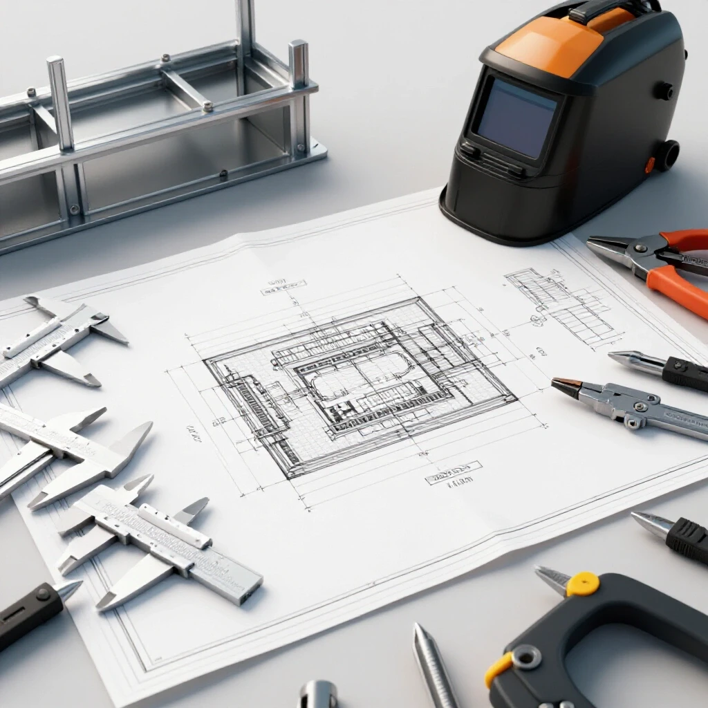
When you work in a home shop, the stakes are high. You do not have a team of quality inspectors watching your back. You are the engineer, the fabricator, and the safety officer all in one. This guide is built from the lessons I learned the hard way. We will look at how to map out a build, analyze the stress points, and organize your workspace to ensure that what you build stays standing.
Defining the Structural Scope and Load Requirements
Scoping a project involves identifying the specific forces that will act upon a metal assembly during its lifetime. This stage requires you to calculate both static loads, which are constant weights, and dynamic loads, which involve movement or vibration. By defining these requirements early, you prevent material failure and ensure the structure remains stable under pressure.
To start, you must understand the structural metal load capacity. This is the maximum weight a piece of metal can support before it begins to deform permanently. When I plan a build, I look at the yield strength of the material. For example, standard A36 structural steel has a yield strength of about 36,000 PSI. This means if you apply more pressure than that, the steel will stretch like taffy and won’t snap back.
I always apply a safety factor to my plans. For most hobbyist projects, a 2:1 safety factor is the bare minimum, but for anything overhead or supporting people, I move to a 4:1 ratio. This means if I expect a shelf to hold 500 pounds, I design it to handle 2,000 pounds. This buffer accounts for small errors in welding or slight variations in material quality.
Mapping Load Shear Paths
Load shear paths are the invisible routes that weight takes as it travels through your structure toward the ground. Understanding these paths allows you to place supports exactly where they are needed most. If a path is interrupted by a weak joint or an unbraced corner, the structure will eventually fail at that specific point.
When I map out a frame, I draw arrows showing where the weight goes. If I am building a workbench, the weight on the top must travel through the frame and down the legs. If the legs are attached to the side of the frame with only a few tacks, that weight is “shearing” against the welds. I prefer to design joints where the vertical member sits directly under the horizontal member. This uses the compressive strength of the metal rather than relying solely on the strength of the weld bead.
| Material Type | Typical Yield Strength (PSI) | Common Use Case |
|---|---|---|
| A36 Carbon Steel | 36,000 | Frames, brackets, general shop use |
| 6061-T6 Aluminum | 35,000 – 40,000 | Lightweight structures, carts |
| 304 Stainless Steel | 30,000 | Food-grade projects, outdoor use |
| Grade 50 Steel | 50,000 | Heavy-duty trailers, lifting arms |
Material Selection and Internal Stress Factors
Selecting the right metal involves more than just picking a thickness; it requires an understanding of how that metal reacts to heat and pressure. Different alloys have different thresholds for stress, and their internal grain structure changes when you weld them. Choosing the wrong material for a specific design can lead to brittle fractures or unexpected warping.
One of the most overlooked parts of material selection is the heat affected zone weakness. The Heat Affected Zone (HAZ) is the area of metal immediately surrounding a weld. While this metal didn’t melt, it got hot enough to change its molecular structure. In many cases, the HAZ becomes more brittle or softer than the original metal. If you are building a trailer tongue out of high-strength steel, the area right next to your weld might actually be the weakest point of the entire project.
Managing Material Distortion Risks
Material distortion occurs when the heat from a welding arc causes the metal to expand and then contract as it cools. This movement can pull a perfectly square frame out of alignment by a fraction of an inch or even several degrees. Planning for this movement is essential to ensure that your finished project actually fits together.
I have seen many builders get frustrated when a door frame won’t close because it “pulled” during assembly. To prevent this, I use a sequence of small tack welds rather than long, continuous beads. This distributes the heat more evenly. I also plan my cuts to include a small “gap” for the weld to fill, which helps reduce the internal tension that leads to warping.
- Always clean your material to shiny metal before starting.
- Account for a 1/16-inch “shrinkage” factor across long joints.
- Use thicker wall tubing for structural bases to resist twisting.
- Avoid over-welding; more metal doesn’t always mean more strength.
Sequencing the Assembly Process
Sequencing is the logical order in which you cut, fit, and join your components to maintain accuracy. A good sequence ensures that you have access to all joints and that the heat is managed throughout the build. Without a clear order of operations, you may find yourself unable to reach a critical joint or facing massive alignment issues.
When I plan a sequence, I start from the inside out. I build sub-assemblies first. For a large table, I might build the two end frames separately, check them for square, and then join them with the long rails. This allows me to fix any errors on a small scale before they compound into a massive problem. If you weld everything at once, the cumulative heat will almost certainly twist the entire structure.
Fixturing and Tack Welding Strategies
Fixturing involves using clamps, magnets, and heavy tables to hold metal in place during the joining process. Tack welding is the practice of using tiny, temporary welds to “stitch” the project together before the final passes are made. Together, these techniques act as a physical insurance policy against movement and misalignment.
I never perform a final weld until the entire project is tacked together and measured. I use a “cross-stitch” pattern for tacks, jumping from one corner to the opposite corner. This keeps the heat from building up in one spot. If I find that the frame is 1/8 of an inch out of square, I can easily cut a tack with a thin grinding wheel and reset it. Once you lay down a full bead, making corrections becomes a nightmare of grinding and wasted material.
Workshop Safety and Layout Planning
A safe workshop layout minimizes the risk of fire, tripping, and exposure to harmful fumes or light. Planning your space is just as important as planning your metal cuts, especially when working with heavy or awkward components. A cluttered shop leads to “close calls” that can easily turn into serious injuries.
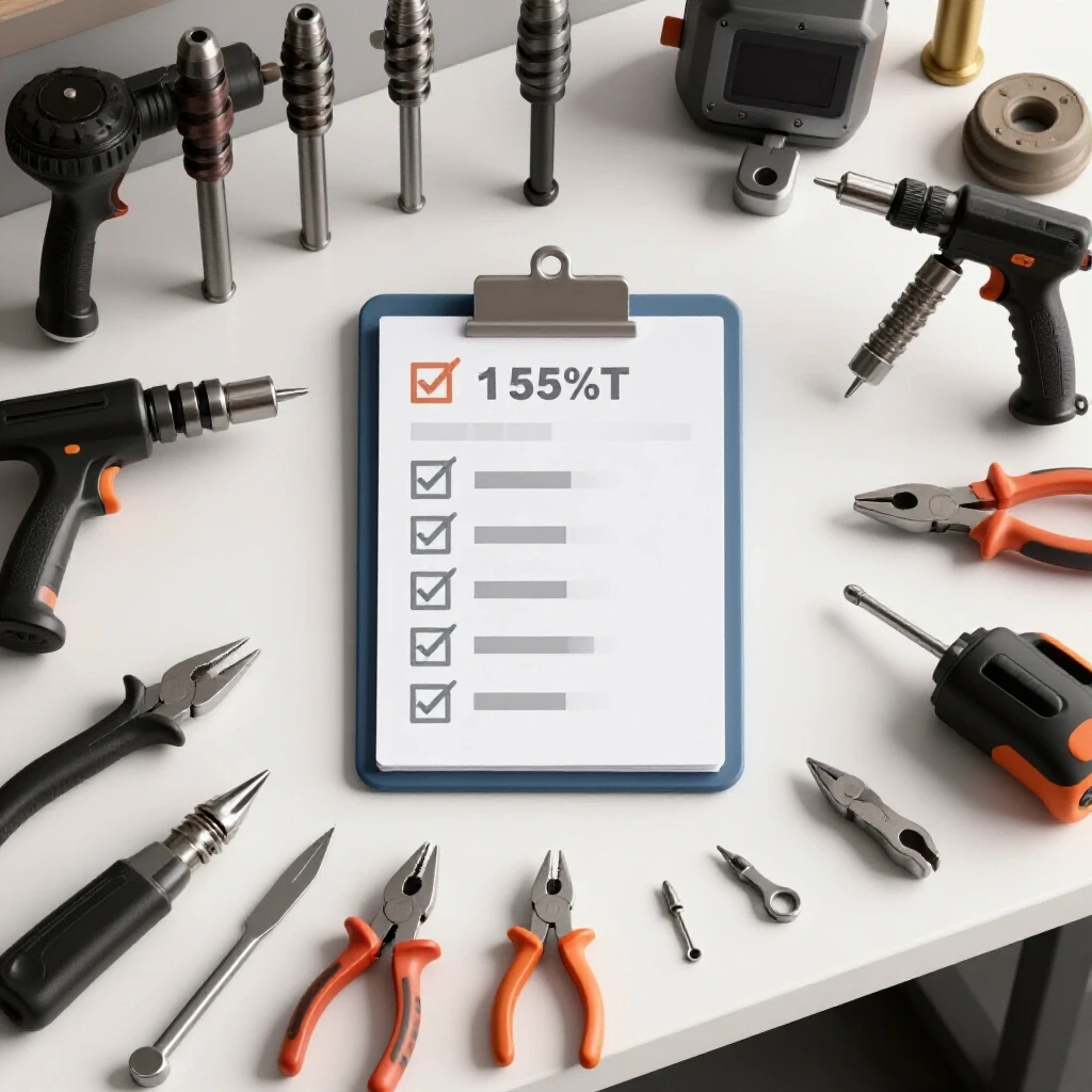
I follow a strict workshop safety checklist before I even plug in a machine. This includes clearing a five-foot radius around my work area of any flammable materials like sawdust or oily rags. I also ensure my welding cables are not coiled, as coiled cables can create heat through induction. In a small garage, ventilation is your biggest hurdle. I use a high-cfm fan to pull air away from my face, ensuring that I am not breathing in metallic dust or shielding gas.
Integrating PPE and Eye Protection
Personal Protective Equipment (PPE) is your last line of defense against the hazards of metalwork, including UV radiation and flying debris. Choosing the right gear requires understanding the specific risks of your process, such as the intensity of the arc light. Proper PPE allows you to focus on the quality of your work without the distraction of physical discomfort or fear.
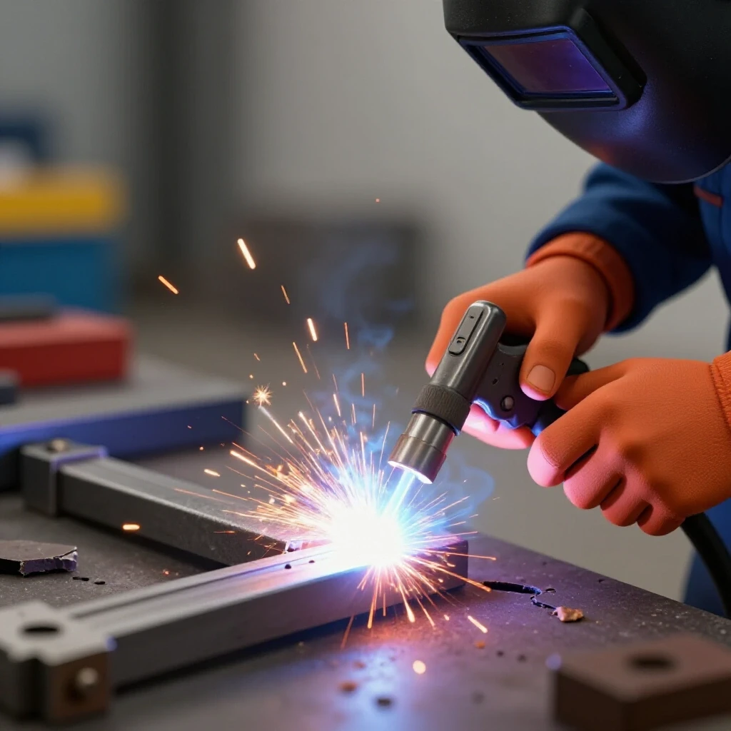
For most of my work, I use an auto-darkening helmet with Shade 10-13 filters. I prefer a helmet with a large viewing area so I can see the joint clearly before I strike the arc. I also wear leather sleeves and a bib. Many people think a t-shirt is fine for a quick tack, but the UV light from an arc can cause a “welder’s burn” (essentially a severe sunburn) in just a few minutes.
| Safety Item | Requirement/Rating | Purpose |
|---|---|---|
| Welding Helmet | Shade 10 – 13 | Protects eyes from UV/IR light |
| Respirator | P100 Rated | Filters out toxic metal fumes |
| Gloves | Top-grain Leather | Protects from heat and sharp edges |
| Fire Extinguisher | Class ABC | Essential for electrical and chemical fires |
| Ventilation | 200+ CFM Fan | Removes hazardous smoke from the zone |
Contingency Mapping and Error Prevention
Contingency mapping is the process of identifying what could go wrong during a build and having a plan to fix it. This involves looking for potential “fail points,” such as areas where a weld might be difficult to reach or where the metal is too thin for the heat. By anticipating these issues, you reduce the frustration of wasted time and material.
I use a welding defect troubleshooting mindset throughout the build. If I see “porosity”—which looks like tiny holes or bubbles in the weld—I stop immediately. Porosity is usually caused by a low welding gas flow rate or a draft blowing the shielding gas away. In a garage, even a small breeze from an open door can ruin a weld. I typically set my flow meter to 15–20 CFH (cubic feet per hour) to ensure the molten metal is fully protected from the air.
Identifying Internal Weld Defects
Internal defects are flaws that exist beneath the surface of a weld bead, such as lack of fusion or slag inclusions. These defects are dangerous because they can’t always be seen with the naked eye, yet they significantly reduce the strength of a joint. Learning to spot the signs of these issues during the process is key to building a sound structure.
- Undercut: A groove melted into the base metal next to the weld. It creates a “perforation” line where the metal is now thinner and prone to cracking.
- Lack of Penetration: The weld sits on top of the metal rather than melting into it. This is often caused by the metal being too cold or the travel speed being too fast.
- Slag Inclusions: Bits of flux trapped inside the weld. This happens if you don’t clean between passes on a multi-run weld.
- Crater Cracks: Small cracks at the very end of a weld bead. I prevent these by “doubling back” at the end of a weld to fill the hole before pulling away.
Final Verification and Load Testing
Verification is the final step where you confirm that the project meets the original requirements and is safe for use. This phase includes visual inspections, measuring for squareness, and sometimes performing a controlled load test. Skipping this step means you are simply hoping the project works, which is a risk no fabricator should take.
Once a build is complete, I perform a “ring test” on critical joints. I tap the metal with a small hammer; a solid joint will produce a clear, metallic ring. A dull “thud” can sometimes indicate a hollow or cracked weld. For projects that will hold significant weight, I perform a static load test. I apply the expected weight in a controlled environment, using jack stands or straps to catch the load if something fails. I look for any signs of deflection or “pinging” sounds, which indicate the metal is stretching or the welds are under too much tension.
Creating a Post-Fabrication Checklist
A checklist provides a standardized way to review your work and ensure no small details were missed. This final review is your opportunity to catch errors that could lead to long-term fatigue or sudden failure. It acts as a formal “sign-off” on the safety and integrity of the project.
- Check all joints for visible cracks or undercut.
- Verify that all critical fasteners are tightened to the correct torque.
- Ensure there are no sharp edges or burrs that could cause injury.
- Confirm the structure sits level and does not wobble under its own weight.
- Test any moving parts for smooth operation without binding.
Frequently Asked Questions
How do I know if my weld is strong enough for a heavy load? A strong weld should have a consistent profile with no visible holes or deep grooves at the edges. It should look like it has “melted into” the base metal rather than just sitting on top. If the weld is the same thickness as the metal you are joining, and you have achieved full penetration, the joint is typically as strong as the metal itself.
What is the best way to prevent a frame from warping? The best way to prevent warping is to control the heat. Use many small tack welds to hold the frame in place before doing any long welds. Always weld in short sections and jump around to different parts of the frame to let the metal cool. This prevents one area from getting too hot and pulling the rest of the structure out of alignment.
Is it safe to weld on painted or galvanized metal? No, it is not safe. Welding on paint or galvanized coatings releases toxic fumes that can cause serious illness, such as “metal fume fever.” Always grind off all coatings, rust, and oil until you have bright, shiny metal at least one inch away from where you plan to weld.
How much gap should I leave between two pieces of metal? For structural joints, a small gap (about 1/16 to 3/32 of an inch) is often helpful. This “root opening” allows the weld to penetrate all the way through the thickness of the metal. If the pieces are pressed tight together, you might only be welding the very surface, which creates a much weaker joint.
What should I do if I hear a “pinging” sound after I finish a weld? A pinging sound is usually the sound of the metal cracking or the weld pulling away as it cools. This happens due to extreme internal stress. If you hear this, you need to inspect the joint closely with a magnifying glass. You may need to grind out the weld and restart with a better heat management plan.
How do I calculate the weight my project can hold? You can look up the “yield strength” of your specific metal (like A36 steel) and use the cross-sectional area of your supports to find the capacity. However, the simplest way for a home shop is to find a “load table” for the specific size and thickness of the tubing or angle iron you are using. Always divide that number by a safety factor of at least two.
Why is my welding gas running out so fast? You might have your welding gas flow rate set too high. For most indoor shop work, 15 to 20 CFH is plenty. If you set it to 40 or 50 CFH, you are wasting gas and can actually create turbulence that sucks air into the weld, causing defects. Also, check your hose connections with soapy water to look for leaks.
What is the “Heat Affected Zone” and why should I care? The Heat Affected Zone is the area next to the weld that got hot but didn’t melt. This area often becomes the weakest part of the structure because the heat changed the metal’s properties. In high-stress projects, failures almost always happen in the HAZ rather than in the weld itself.
How can I tell if my structure is “square” if it’s too big for a square tool? Use the “3-4-5” rule or measure the diagonals. If you measure from one corner to the opposite corner, and then do the same for the other two corners, the numbers should be exactly the same. If they are different, your frame is a trapezoid rather than a rectangle.
Do I really need a respirator if I’m welding in my garage? Yes. Even if you have the door open, the fumes from welding contain microscopic bits of metal and chemicals that stay in the air. A P100-rated respirator fits under your welding mask and is the best way to protect your lungs from long-term damage.
(This article was written by one of our staff writers, James Harlan. Visit our Meet the Team page to learn more about the author and their expertise.)