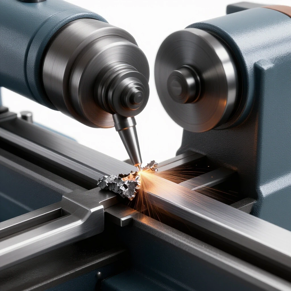
How to Reduce Tool Vibration on Metal Mills (DIY Tutorial)
I remember standing over a small knee mill late on a Tuesday night, staring at a piece of 4140 steel that looked like it had been chewed by a serrated knife. I was trying to take a simple 0.050-inch deep pass with a half-inch end mill, but the high-pitched scream coming from the spindle was enough to set my teeth on edge. No matter how much I adjusted the dials, the finish stayed rough, and the tool eventually snapped. That was fifteen years ago, and it was the moment I realized that “guessing” at machine settings is a recipe for broken tools and wasted material.
In my years as a diagnostic specialist, I have learned that mechanical issues are rarely a mystery if you have a system. Whether you are dealing with a benchtop mill or a manual knee mill, unwanted movement in the cutting process is usually a sign of a breakdown in rigidity. It could be the spindle, the workholding, or the tool itself. My goal is to help you stop the guesswork and start using a structured approach to stabilize your machining operations.
When a machine starts to vibrate, it is trying to tell you that something is out of balance or loose. We call this “chatter,” and it is essentially a self-excited vibration that occurs when the tool and the workpiece are not moving in harmony. By breaking the problem down into mechanical, operational, and structural categories, we can isolate the root cause and get back to making clean, precise cuts.
Establishing a Diagnostic Framework for Mill Stability
A diagnostic framework is a structured method used to isolate variables one at a time to find the source of a mechanical failure. Instead of changing three settings at once, this process requires making one adjustment and measuring the result. This prevents the “shotgun approach” where you fix a problem without knowing why.
When I walk into a shop to help a fabricator, the first thing I do is look for the “low-hanging fruit.” This means checking the simplest mechanical points before tearing into a spindle. I use a process called variable isolation. If the finish is poor, I change the tool. If it stays poor, I change the feed rate. If it still persists, I look at the machine’s physical alignment.
To build your own diagnostic path, you need to document what you see. I recommend keeping a small logbook next to your mill. Note the material, the tool diameter, the RPM, and the specific sound the machine makes. Over time, you will notice patterns. For instance, if a specific frequency occurs only during heavy lateral cuts, you likely have an issue with your Y-axis gibs or table locks.
- Step 1: Observation. Listen to the pitch. High-pitched squeals often indicate tool-related issues, while low-frequency thumping usually points to spindle or bearing problems.
- Step 2: Isolation. Change one factor (like the RPM) by 10 percent and observe the change in the surface finish.
- Step 3: Verification. Once you think you have found the cause, revert the change to see if the problem returns. This confirms the diagnosis.
Identifying the Root Causes of Machining Chatter
Machining chatter is a resonant vibration that happens when the cutting forces fluctuate in a way that matches the natural frequency of the machine. It is a cycle where the tool deflects, skips, and then digs back into the material. Understanding this cycle is the first step toward eliminating it.
There are two main types of vibration we deal with in a mill: forced and self-excited. Forced vibration is caused by something physically out of balance, like a chipped tooth on a gear or a bent spindle. Self-excited vibration, or chatter, is more common and happens even when the machine is technically in good repair. It is a result of the “springiness” of the setup.
Think of your end mill as a very stiff spring. When it hits the metal, it bends slightly. If it snaps back at the same time a new flute hits the material, the vibration grows. This is why changing the speed even slightly can sometimes “break” the harmonic and stop the noise.
| Vibration Type | Common Sound | Primary Cause | Typical Fix |
|---|---|---|---|
| Forced Vibration | Constant thumping or rhythmic hum | Out-of-round spindle or bad bearings | Replace bearings or balance the spindle |
| Self-Excited Chatter | High-pitched scream or “singing” | Tool deflection or lack of setup rigidity | Shorten tool stick-out or adjust feed/speed |
| Resonant Harmonics | Intermittent “ringing” at specific RPMs | Machine frame or table resonance | Change RPM or add mass to the setup |
Mechanical Alignment and Spindle Play Adjustments
Mechanical alignment refers to the physical position and “tightness” of the machine’s moving parts, such as the spindle, table, and gibs. When these parts have too much “play” or backlash, they allow the tool to move in unintended directions. Adjusting these tolerances is essential for maintaining a rigid cutting environment.
I have seen many fabricators blame their tooling when the real culprit was a loose gib. A gib is a tapered strip of metal that takes up the space between the sliding parts of your mill’s ways. If the gib is loose, the table can rock back and forth under the pressure of the cut. This movement is a primary source of instability.
To check for this, I use a dial indicator. Place the indicator on the table and push against it with your hand. If you see more than 0.001 to 0.002 inches of movement, your gibs need tightening. Similarly, you should check the spindle for “runout.” This is how much the tool wobbles as it rotates. Ideally, you want less than 0.0005 inches of runout for clean milling.
- Adjusting the Gibs: Tighten the gib screw until the table is difficult to move, then back it off a quarter turn. The table should move smoothly but feel “heavy.”
- Checking Backlash: Backlash is the “dead space” in your lead screws. If you have more than 0.005 inches of backlash on an older manual mill, you must always “climb” your cuts carefully or adjust the lead screw nut if your machine allows it.
- Spindle Bearing Preload: If the spindle has vertical movement, the bearings may need to be preloaded. This involves tightening the spindle nut to remove any axial play.
Strategies for Dampening Tool Resonance and Deflection
Dampening is the process of absorbing or reducing the energy of a vibration. In milling, we do this by shortening the tool’s length, using heavier workholding, or adding materials that soak up the “ringing” of the metal. Reducing the distance a tool sticks out is the most effective dampening strategy.
One of the most common mistakes I see is “tool stick-out.” This is the distance from the bottom of the collet to the tip of the end mill. The longer the tool, the more it acts like a diving board. A tool that is twice as long is actually eight times more likely to deflect. I always tell my students: “Choke up on the tool as much as possible.”
If you must use a long tool, you have to compensate by reducing your depth of cut. Another trick I use in the shop is adding “mass” to the workpiece. If I am milling a thin plate that is ringing like a bell, I might clamp a heavy block of scrap steel to it. That extra weight changes the natural frequency of the part, often killing the chatter instantly.
- The 3:1 Rule: Try to keep your tool stick-out to no more than three times the diameter of the tool. For a 1/2-inch end mill, that means no more than 1.5 inches of exposed tool.
- Collet Quality: Ensure your collets are clean. A single piece of metal dust inside a collet can cause the tool to sit at an angle, creating massive vibration.
- Dampening Interfaces: Sometimes, placing a thin piece of paper or specialized shim stock between the workpiece and the vise can help absorb micro-vibrations.
Calculating Speeds and Feeds to Bypass Harmonic Frequencies
Speeds and feeds refer to the rotational speed of the tool (RPM) and the speed at which it moves through the material (Inches Per Minute). Finding the “sweet spot” involves balancing these two numbers so that the tool is always cutting a clean chip rather than rubbing or bouncing.
When you hear that dreaded scream, your first instinct might be to slow down the feed rate. Interestingly, this often makes the problem worse. If you slow the feed too much, the tool stops “cutting” and starts “rubbing.” Rubbing creates heat and friction, which excites the vibration. Sometimes, the fix is actually to increase the feed rate to put more load on the tool, which “sets” it into the cut and stops the bouncing.
I use a simple calculation for Feed Per Tooth (IPT). For most mild steels, you want an IPT of 0.002 to 0.005 inches. If you are running a 4-flute end mill at 1,000 RPM, a feed rate of 12 Inches Per Minute (IPM) gives you a 0.003 IPT. If the machine starts to vibrate, try increasing that IPM to 15. If the vibration deepens in tone, you are going the right way.
- Calculate RPM: (Cutting Speed x 4) / Tool Diameter. For mild steel, use a cutting speed of 100.
- Calculate Feed (IPM): RPM x Number of Flutes x Feed Per Tooth.
- Adjusting for Stability: If chatter occurs, decrease RPM by 10% but keep the feed rate the same. This increases the chip load and can stabilize the cut.
Troubleshooting Workholding and Fixture Rigidity
Workholding is the method used to secure the metal being machined, usually a vise or clamps. If the workpiece can move even a fraction of a millimeter, the energy from the tool will cause the part to vibrate. Rigidity in the setup is just as important as rigidity in the machine itself.
I once spent four hours trying to fix a “spindle issue” only to realize the vise wasn’t bolted down tight enough to the table. It sounds simple, but under the heavy forces of milling, even a heavy cast-iron vise can shift. Always clean the “ways” of your table before mounting a vise. Any debris underneath will create an air gap that acts like a spring.
Another common issue is “part lift.” When you tighten a standard vise, the movable jaw often tilts up slightly, lifting your workpiece off the parallels. I always use a dead-blow hammer to “set” the part onto the parallels after tightening the vise. If the parallels can still slide around under the part, your work is not secure, and it will vibrate.
- Vise Alignment: Use a dial indicator to “sweep” the back jaw of your vise. It should be parallel to the table’s travel within 0.0005 inches over the length of the jaw.
- Clamping Pressure: For thin materials, use “sacrificial” backing plates. A piece of aluminum or even plywood behind a thin part can provide the structural support needed to prevent “oil-canning” or vibration.
- Parallels Check: After clamping, always try to tap the parallels. If they move, the part is “floating” and will chatter.
Case Study: The Mystery Rattle in a 2-HP Knee Mill
A few years ago, a fellow fabricator called me about a rhythmic thumping in his mill that was ruining his surface finishes. He had already replaced the end mill and the vise, but the problem remained. It didn’t sound like high-pitched chatter; it sounded like a mechanical “knock.”
I started by checking the spindle runout. It was within 0.0005 inches, which is excellent. Next, we looked at the drive belt. I noticed the belt had a small “set” or a flat spot from sitting in one position for too long. Every time that flat spot hit the pulley, it caused a tiny vibration that translated through the spindle to the tool.
We replaced the $20 belt, and the “mystery rattle” disappeared. This taught me a valuable lesson: always look at the entire drive train. Vibration isn’t always born at the cutting edge; sometimes it is delivered there from the motor or the pulleys.
A Step-by-Step Tool Calibration Checklist
To keep your mill running smoothly, I recommend performing a “rigidity audit” once a month. This systematic check helps you catch small issues before they become “electrical gremlins” or mechanical failures that shut down your shop.
- Clean and Oil the Ways: Remove all chips and apply a fresh coat of way oil. Dry ways create friction and “stick-slip” movement.
- Test the Gibs: Use a dial indicator to check for table rock. Adjust as needed to maintain 0.001-inch tolerances.
- Inspect the Spindle Taper: Use a clean rag to wipe the inside of the spindle. Any grit here will cause tool runout and vibration.
- Check Belt Tension: Ensure drive belts are tight but not over-strained. Over-tightened belts can wear out spindle bearings prematurely.
- Verify Table Alignment: Use a “tramming” tool or a dial indicator in the spindle to ensure the head is perfectly square to the table. A “nodding” head is a major cause of uneven cutting forces and chatter.
Frequently Asked Questions
What is the most common cause of tool chatter on a manual mill? The most common cause is excessive tool stick-out. When the tool is too long relative to its diameter, it lacks the rigidity to resist cutting forces, leading to resonant vibration. Always seat the tool as deeply as possible in the collet or holder.
How can I tell if my spindle bearings are going bad? Bad bearings usually produce a low-frequency growl or heat up significantly during use. You can check them by placing a dial indicator on the spindle nose and pulling on it. Any measurable “play” or movement usually indicates the bearings need replacement or preloading.
Does the type of material I am cutting affect vibration? Yes. Harder materials like stainless steel require more cutting force, which can excite vibrations more easily. Conversely, very soft materials like aluminum can “gum up” the flutes of a tool, leading to an unbalanced load that causes the machine to shake.
Why does increasing my feed rate sometimes stop the vibration? Increasing the feed rate increases the “chip load,” which puts more constant pressure on the tool. This pressure can “pre-load” the machine’s components, taking up the tiny amounts of play in the bearings and gibs, which stops the tool from bouncing.
Can I use a “fly cutter” to reduce vibration on a small mill? Actually, fly cutters can sometimes increase vibration because they are unbalanced by design. They create an interrupted cut that “shocks” the machine once per revolution. If you use one, ensure your mill’s head is perfectly trammed and use a lower RPM.
What is “climb milling” and does it help with stability? Climb milling is when the tool “pulls” itself into the cut. On a rigid CNC, it provides a better finish. However, on a manual mill with backlash in the lead screws, climb milling can be dangerous because the tool can “grab” the table and pull it forward, causing a massive vibration or tool breakage.
How do I know if my mill head is “out of tram”? If you move your table and the tool leaves a “step” or a visible mark between passes, your head is likely tilted. You can verify this by putting a dial indicator in the spindle and sweeping it in a large circle on the table. The reading should be the same at all points.
Does the number of flutes on an end mill matter for vibration? Yes. A tool with more flutes (like a 4-flute or 6-flute) is generally more rigid than a 2-flute tool. However, 2-flute tools have more room for chips. For finishing passes where vibration is a concern, a higher flute count can help stabilize the cut.
Can the floor of my shop cause milling issues? Surprisingly, yes. If a mill is not leveled or is sitting on a thin, vibrating concrete slab, the entire machine can develop a resonance. Using leveling pads or bolting the machine to a thick concrete floor can significantly reduce “harmonic ringing.”
What tools do I need for basic vibration troubleshooting? At a minimum, you need a high-quality dial indicator with a magnetic base, a set of feeler gauges, a tramming bar, and a dead-blow hammer. These tools allow you to measure tolerances rather than guessing.
Managing the stability of your milling operations is a skill that takes time to develop. It is about moving from “reactive” fixing to “proactive” diagnostics. By understanding the relationship between the machine’s mechanical state and the physics of the cutting process, you can turn a frustrating, noisy shop into a precision environment. Start with the basics, measure everything, and never stop refining your setup.
(This article was written by one of our staff writers, Paul Whitaker. Visit our Meet the Team page to learn more about the author and their expertise.)