How to Safely Troubleshoot Electric Motor Faults (DIY Guide)
I’ve spent nearly two decades in fabrication shops, and if there is one thing I’ve learned, it’s that a machine never fails at a convenient time. You’re halfway through a critical pass on the lathe or finishing a structural weldment when the hum of the motor changes or, worse, disappears entirely. The silence that follows is usually filled with the mental math of lost productivity and missed deadlines. For many fabricators, the instinct is to start swapping parts or poking at wires, but that’s a fast track to frustration.
In my years as a diagnostic specialist, I’ve found that most workshop equipment failures follow a predictable pattern. Whether it’s a mill that won’t start or a belt sander that’s lost its torque, the problem usually hides in the intersection of mechanical resistance and electrical integrity. My goal is to help you move away from guesswork and toward a systematic approach to identifying why your machinery has gone dark. We aren’t looking for a “quick fix” here; we are looking for the root cause using the same methodical steps I use when a million-dollar production line goes down.
Establishing a Systematic Metalworking Diagnostic Framework
A diagnostic framework is a structured set of steps used to narrow down the cause of a machine failure by eliminating variables one by one. By following a consistent path, you avoid the “parts cannon” approach and ensure that the repair you make is actually the one required.
The first step in any diagnostic process is observation. Before you even pick up a tool, you need to look, smell, and listen. I remember a case in a custom shop where a large drill press was tripping the breaker every time it started. The operator was convinced the motor was shot. I walked over and noticed a faint scent of burnt ozone near the switch, not the motor. By observing the environment first, I saved the shop from buying a $400 motor they didn’t need.
Once you’ve observed the symptoms, you move to isolation. This means separating the motor from the load it’s driving. If a bandsaw motor is struggling, is it because the motor is weak, or because the blade guides are seized? In my experience, about 40% of “motor faults” are actually mechanical issues elsewhere in the machine.
- Observation: Document exactly what happened when the failure occurred.
- Isolation: Disconnect belts or couplings to test components individually.
- Variable Control: Only change or test one thing at a time to see how it affects the outcome.
Identifying Mechanical Resistance and Spindle Binding
Mechanical binding occurs when physical friction or a blockage prevents a shaft from rotating freely, often mimicking an electrical failure. Checking for this ensures you aren’t chasing an electrical ghost when the real culprit is a seized bearing or a jammed gear.
Before you ever touch a multimeter, you must ensure the motor is physically capable of turning. I always start by unplugging the machine—and I mean physically pulling the cord from the wall. Then, I try to rotate the motor shaft by hand. If it’s a direct-drive grinder, I spin the wheel. If it’s a lathe, I move the belts to see if the spindle and motor turn without excessive force.
I once worked on a cold-saw that wouldn’t start. The owner was ready to pull the motor. When I tried to turn the blade by hand, it wouldn’t budge. We found a small offcut of stainless steel wedged between the blade and the guard. The motor was fine; it was just doing its job by tripping the thermal overload to prevent a fire.
| Component | Normal Feel | Red Flag Symptom |
|---|---|---|
| Motor Shaft | Smooth, slight resistance from internal fans | Gritty feeling, won’t turn, or excessive side-play |
| Spindle Bearings | Consistent drag, quiet rotation | High-pitched squeal or “clunking” when rotated |
| Drive Belts | Firm but flexible, no fraying | Glazed appearance, cracked ribs, or slipping |
| Gearbox | Solid engagement, heavy but smooth | Metallic grinding noise or “dead spots” in rotation |
Visual Inspection of Power Leads and Termination Points
A visual inspection is the process of looking for physical damage like frayed wires, loose terminals, or burnt components that indicate a break in the electrical path. This is the simplest way to find “electrical gremlins” without needing complex tools.
Once you’ve confirmed the machine isn’t jammed, it’s time to look at the delivery system. Most workshop motors are single-phase and rely on a few key connections. I start at the plug. Look for pitted or blackened prongs, which indicate arcing. Move down the cord, feeling for soft spots or kinks where the internal copper might have fractured.
Inside the connection box on the motor itself, I look for loose wire nuts or vibrating terminals. In a high-vibration environment like a fabrication shop, screws can back out over time. I’ve seen cases where a vibrating vibratory tumbler literally shook its own power leads loose. If you see a wire that looks “toasted”—meaning the insulation is brittle or discolored—you’ve likely found a high-resistance point that’s starving the motor of power.
- Check the plug for heat damage or loose prongs.
- Inspect the power cord for cuts from metal chips or heavy equipment.
- Open the motor junction box and check for loose screw terminals.
- Look for any signs of “smoke tracks” on the internal plastic components.
Using a Multimeter for De-Energized Continuity Testing
Continuity testing is a way to check if an electrical path is continuous (unbroken) using a multimeter set to measure resistance (Ohms). If the path is broken, the motor cannot complete its circuit and will not run.
Now we get into the data. For this, your machine must remain unplugged. We are measuring resistance, not voltage. Set your multimeter to the Ohms (Ω) setting. We are looking for “continuity,” which means electricity can flow from point A to point B.
I start by testing the power cord. I put one probe on the plug prong and the other on the corresponding wire inside the motor junction box. I should see a reading close to 0.2 to 0.5 Ohms. If the meter reads “OL” (Open Line), the cord is broken internally. I then check the motor windings. While I won’t go into internal motor repair, a simple check between the two main power leads of the motor should show a low, steady resistance. If it’s “OL,” the internal windings are likely severed, and the motor is a “boat anchor.”
Common Resistance Benchmarks for Workshop Motors: 1. Power Cord (Prong to Terminal): < 1.0 Ohm 2. Switch (Closed Position): < 0.5 Ohms 3. Motor Windings (Small 1HP motor): 2.0 to 20.0 Ohms (Varies by size) 4. Ground Path (Chassis to Ground Prong): < 0.5 Ohms
Why Machining Chatter Ruins Tools and How to Isolate Vibrations
Machining chatter is a resonant vibration that occurs when the cutting tool and the workpiece bounce off each other, leaving a wavy finish. Motor health plays a massive role in this because an unstable motor can trigger these harmonics.
You might not think a motor issue would cause tool chatter, but an unbalanced motor or a failing bearing creates vibrations that travel through the machine frame. I was once called to a shop where a bridge mill was producing a terrible finish. They had changed the tooling, the speeds, and the feeds, but the chatter remained.
I used a simple vibration analysis technique. With the machine running (but not cutting), I placed my hand on the motor housing. I could feel a rhythmic “thrum.” We discovered the motor cooling fan had a broken fin, which created an imbalance. That tiny vibration was being amplified by the machine’s long arm, causing the tool to bounce 0.003 inches at the tip. By replacing the $15 plastic fan, the “unsolvable” chatter disappeared.
- Mechanical Harmonics: When the motor’s vibration frequency matches the machine’s natural frequency.
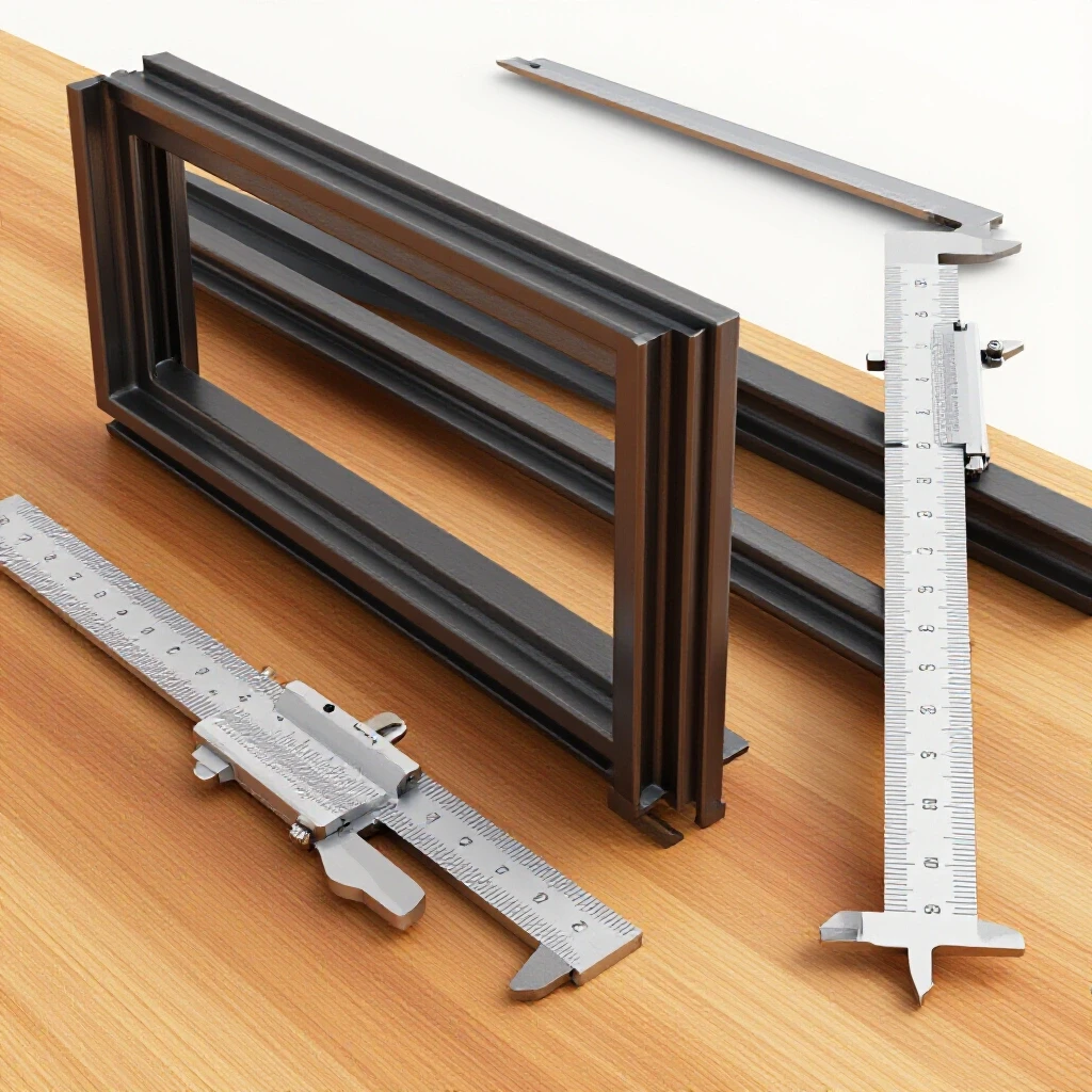
- Spindle Backlash: Excessive play (often over 0.005 inches) that allows vibration to take hold.
- Feed Rate Inconsistency: When a motor fluctuates in speed, the “feed per tooth” changes, triggering chatter.
Diagnosing Weld Porosity Through Power Supply Stability
Weld porosity consists of tiny holes or bubbles in a weld bead, often caused by inconsistent shielding gas or unstable arc voltage. In many cases, a failing wire-feeder motor is the hidden cause of these defects.
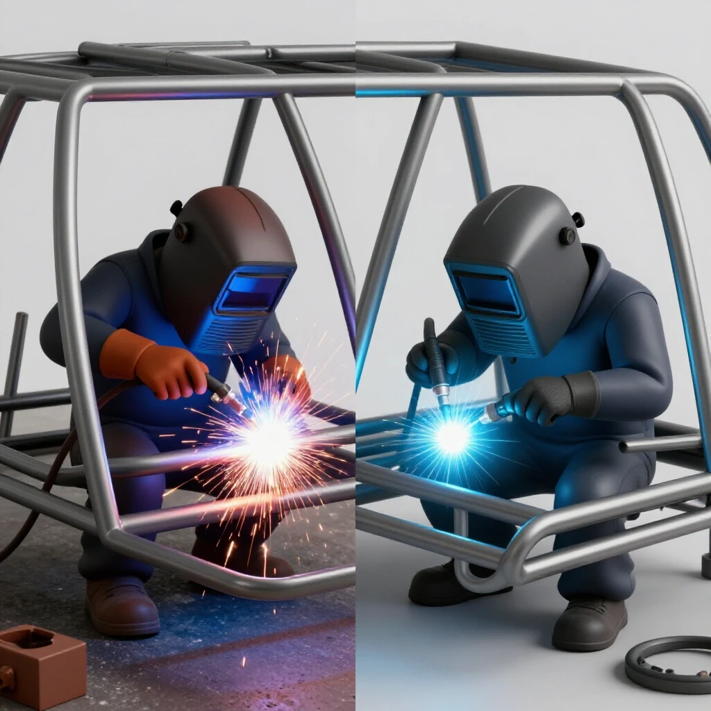
In the welding world, motor issues manifest as “porosity” or “cold laps.” If your MIG welder’s wire-feeder motor is stuttering because of a bad connection or worn brushes, the wire doesn’t enter the weld pool at a constant rate. This creates an unstable arc, which can pull in atmospheric air, leading to porosity.
I once spent three days troubleshooting porosity on a structural job. We checked the gas, the liners, and the tips. Finally, I watched the wire-feeder motor closely. It was surging ever so slightly. We opened the drive assembly and found that the motor’s ground wire was loose. The motor was losing power for fractions of a second, causing the wire to “stutter.” This wasn’t a “welding” problem; it was a motor power delivery problem.
| Defect | Potential Motor-Related Cause | Diagnostic Step |
|---|---|---|
| Porosity | Stuttering wire-feed motor causing arc gaps | Check drive roll tension and motor continuity |
| Cold Laps | Motor speed too slow, causing over-deposition | Verify RPM against wire-speed setting |
| Arc Blow | Magnetic interference from unshielded motor leads | Reroute power cables away from weld leads |
| Burn-Through | Motor surging, pushing too much wire suddenly | Inspect motor controller for loose potentiometers |
Practical Calibration and Maintenance Checklist
To keep your shop running, you need a proactive way to catch these issues before they stop production. I recommend a monthly “walk-around” where you check the vitals of your primary machines. This isn’t just about cleaning; it’s about verifying tolerances.
- Check Belt Tension: A belt that is too tight will ruin motor bearings; too loose, and it will slip and create heat. You should generally have about 1/2 inch of deflection.
- Inspect Brushes: If your motor has external brush caps (common on older mills and grinders), unscrew them. If the carbon brush is shorter than 1/4 inch, replace it.
- Clear Dust: Metal dust is conductive. If it builds up inside a motor or switch box, it can cause a short circuit. Use compressed air to blow out motor housings.
- Verify Grounding: Use your multimeter to ensure the machine frame has less than 0.5 Ohms of resistance to the ground prong of the plug. This is a life-saving check.
- Listen for Bearings: Use a mechanic’s stethoscope (or a long screwdriver held to your ear) to listen to the motor bearings while the machine coasts to a stop. A “rumble” means a replacement is due soon.
The Role of Thermal Overloads and Safety Interlocks
A thermal overload is a protective device that shuts off a motor if it gets too hot, while an interlock is a switch that prevents the machine from starting unless certain conditions (like a guard being closed) are met.
One of the most common “dead motor” calls I get ends up being a tripped thermal overload. These are usually small red buttons on the side of the motor or inside the starter box. They trip because the motor was asked to do too much work, or because the ambient temperature in the shop was too high.
However, if an overload trips repeatedly, don’t just keep resetting it. That’s a signal. Either your mechanical load is too heavy (dull tools, deep cuts), or the motor is struggling with low voltage. I’ve seen fabricators bypass these switches to “get the job done,” only to have the motor burst into flames an hour later. Never bypass a safety device. If it’s tripping, find out why the heat is building up.
- Thermal Overload: Protects the motor windings from melting.
- E-Stop Switches: Can fail internally due to vibration, showing “OL” on a multimeter.
- Limit Switches: Often get gummed up with oil and chips, preventing the motor from receiving a “start” signal.
Learning from the “Dead Ends” of My Career
I’ve had my share of failures in diagnostics. I once spent four hours trying to figure out why a surface grinder wouldn’t start, only to realize the foot pedal had been pushed under a workbench and was slightly depressed, engaging a safety lockout. I was looking for a complex electrical fault when it was a simple mechanical “user error.”
Another time, I replaced a motor on a belt sander because it was “humming but not turning.” The new motor did the exact same thing. It turned out the capacitor—a part I hadn’t tested—was the culprit. While I don’t advise DIYers to mess with capacitors due to the stored charge, that lesson taught me to never assume the most expensive part is the broken one. Always test the path from the wall to the motor before blaming the motor itself.
The key to being a great fabricator isn’t just knowing how to melt metal; it’s knowing how your tools work. When you understand the relationship between the electricity coming out of the wall and the torque at the spindle, you become much more than an operator. You become a technician.
Conclusion and Next Steps
Mastering the basics of machine diagnostics is about reclaiming your time. When a machine stops, you don’t have to feel that sinking sense of helplessness. By unplugging the unit, checking for mechanical binds, performing a visual inspection, and using a multimeter to verify the electrical path, you can resolve the majority of common workshop issues.
Your next step is to go into your shop and perform a “baseline” check on your most important machine. Unplug it, spin the shaft, and check the continuity of the power cord. Knowing what “good” looks like is the only way you’ll be able to spot “bad” when the pressure is on. Keep your tools clean, your connections tight, and your diagnostic process systematic.
FAQ: Troubleshooting Workshop Machinery
Why does my motor hum but refuse to start? This is often caused by mechanical binding or a failure in the starting circuit. First, unplug the machine and see if you can turn the shaft by hand. If it’s locked up, the issue is a bearing or a jam. If it spins freely, the motor may have an internal issue or a faulty starting component that requires professional attention.
How can I tell if a motor is “burnt out” without plugging it in? Perform a “smell test” first; a burnt motor has a very distinct, acrid odor. Then, use a multimeter to check for continuity between the power leads and the motor frame. If you find any continuity (a low Ohm reading) between a power wire and the metal case, the insulation has failed, and the motor is dangerous.
What is the most common cause of intermittent motor failure? Loose connections are the primary culprit. Vibration from grinding or milling can loosen screw terminals over time. Heat causes metal to expand and contract, which can eventually back out a wire nut or a terminal screw, causing the motor to cut in and out.
Can a bad motor cause my welds to look poor? Yes, specifically in MIG or flux-core welding. If the wire-feeder motor isn’t maintaining a constant speed, your arc voltage will fluctuate. This leads to spatter, porosity, and poor penetration. Always check the feeder motor if your weld quality drops suddenly.
How do I use a multimeter to check a power cord? Set the meter to Ohms (Ω). Place one probe on the round ground prong of the plug and the other on the ground wire inside the machine. You should see less than 0.5 Ohms. Repeat this for the “hot” and “neutral” prongs. If any reading is “OL,” the cord has an internal break.
Why does my machine trip the breaker as soon as I turn it on? This usually indicates a “dead short.” A wire might be touching the metal housing, or the motor windings have melted together. It can also happen if the machine is physically jammed, causing the motor to draw massive amounts of “locked rotor” current.
What should I do if my motor feels excessively hot? Most motors are designed to run warm, but if you can’t keep your hand on it for more than a second, it’s overheating. Check for clogged cooling fins, over-tensioned belts, or a dull cutting tool that is forcing the motor to work harder than intended.
Is it safe to blow out a motor with compressed air? Yes, and it’s recommended. Metal dust and wood shavings can act as insulation, keeping heat in, or they can become conductive and cause a short. Ensure the machine is unplugged and use moderate air pressure to clear the internal fans and windings.
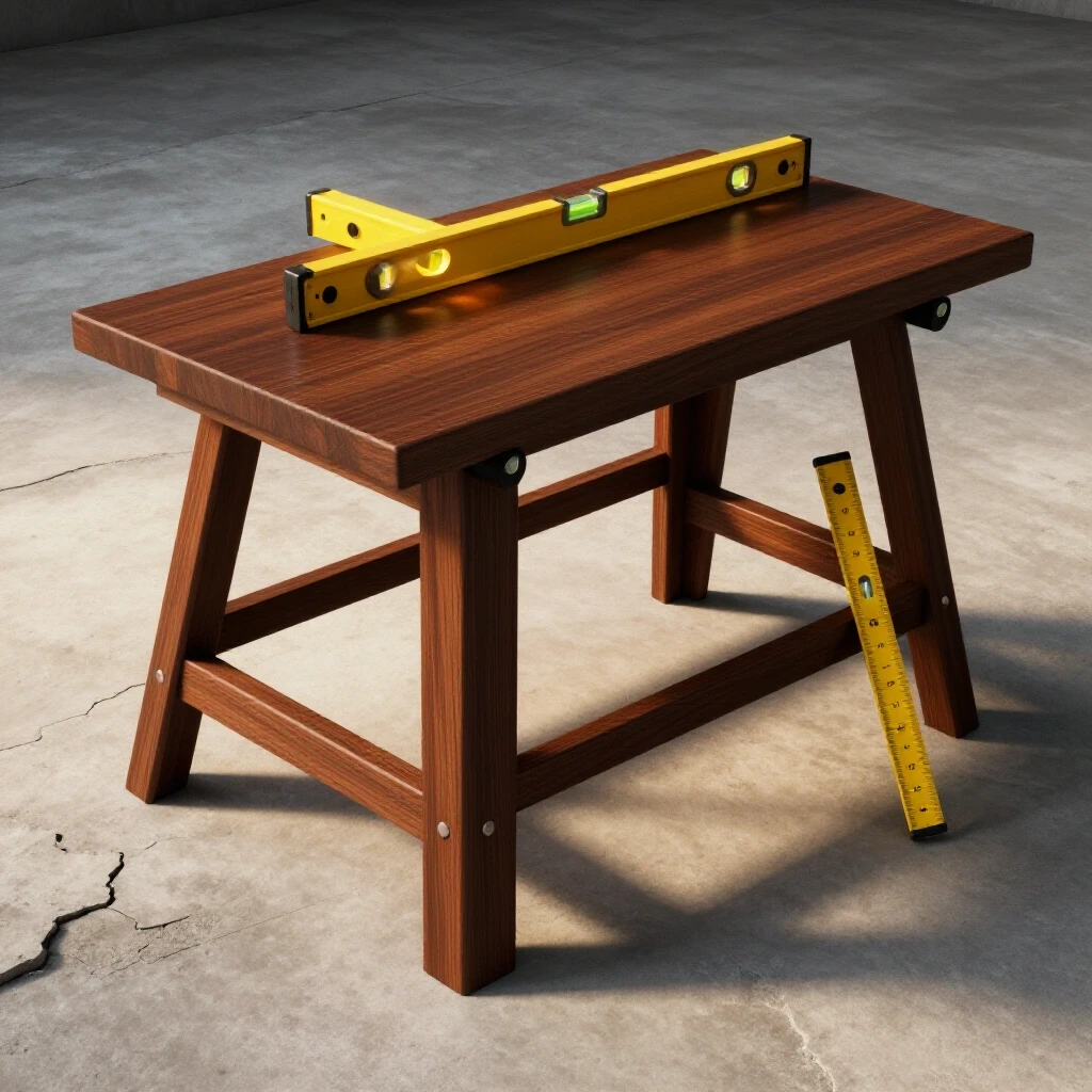
How often should I check my machine’s alignment? For high-precision work, I recommend checking alignment (like lathe tailstock centering or mill head squareness) once a month or after any “crash.” Poor alignment increases the load on the motor and can lead to premature failure.
What is “back-EMF” and why does it matter? Back-Electromotive Force is a voltage created by the motor as it spins, which actually opposes the incoming power. It acts as a natural regulator. If a motor slows down significantly under load, back-EMF drops, and the motor draws more current. This is why “stalling” a motor causes it to burn out so quickly.
(This article was written by one of our staff writers, Paul Whitaker. Visit our Meet the Team page to learn more about the author and their expertise.)