How to Safely Wire a Dedicated Workshop Welder Plug (Guide)
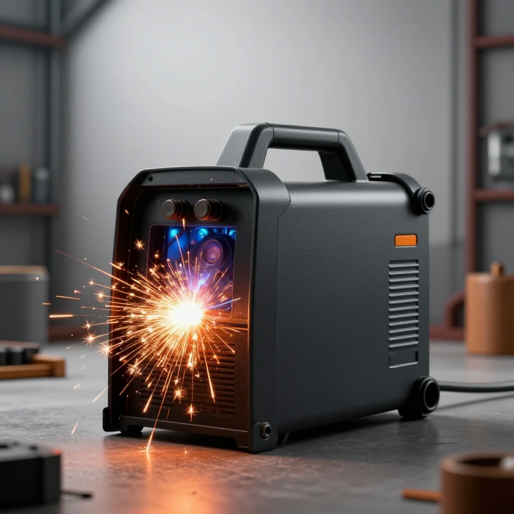
I have spent the last 18 years in industrial fabrication mills and custom shops, and if there is one thing I have learned, it is that a machine is only as good as the power feeding it. I remember a specific case involving a high-end TIG setup that was producing intermittent porosity and arc wander. The fabricator had replaced the gas lens, swapped the tungsten, and even bought a new bottle of argon, yet the issue remained. After three days of frustration, I stepped in with a multimeter. We found that the welder was sharing a circuit with a large compressor. Every time the compressor kicked on, the voltage dropped just enough to destabilize the inverter’s high-frequency board. This is why establishing a dedicated, high-amperage power drop is the first step in any serious metalworking diagnostic guide.
When your equipment behaves unpredictably, the instinct is to look at the tool itself. We check for tool chatter solutions or go through a lathe alignment checklist. However, many mechanical and metallurgical failures are actually electrical “gremlins” born from poor infrastructure. A dedicated circuit ensures that your welder or mill has the “room to breathe” without interference from other shop loads. In this guide, I will break down the systematic process of installing a dedicated 240V workshop power supply, focusing on the technical precision required to eliminate power-related fabrication errors.
Establishing the Foundation of Shop Power Reliability
A dedicated welding circuit is an isolated electrical path consisting of a specific breaker, correctly sized conductors, and a single-use receptacle. This setup prevents voltage fluctuations and electrical noise from affecting sensitive inverter components or motor controllers. By isolating the power source, you remove one of the most common variables in mechanical troubleshooting steps.
In my experience, most shop owners underestimate the impact of voltage drop. If your wire is too thin or your run is too long, the voltage at the machine can sag during high-amperage draws. This sag leads to a weak arc, which causes poor penetration and troubleshooting weld porosity becomes a nightmare because the root cause is invisible. When I design a power drop, I start with the “Rule of Isolation.” Nothing else touches this line. No grinders, no lights, and definitely no heaters.
This isolation is also critical for modern CNC equipment. Back-EMF (electromotive force) from a large motor starting on a shared line can send a spike back through the circuit. This spike can cause a CNC controller to lose its position, leading to structural alignment faults in your workpiece. By wiring a dedicated line, you are essentially building a firewall between your heavy loads and your precision tools.
Sizing Conductors for High-Amperage Welding Loads
Conductor sizing involves selecting the correct wire gauge (AWG) based on the maximum current draw of the machine and the length of the wire run. This process ensures that the wire can carry the load without overheating or causing a significant drop in voltage. Proper sizing is the primary defense against electrical fires and machine performance degradation.
When I look at a welder’s data plate, I am looking for the “I1eff” (effective input current) and “I1max” (maximum input current). These numbers, combined with the duty cycle, dictate the wire size. For a standard 50-amp workshop circuit, many people default to 6-gauge wire. However, if your run exceeds 50 feet, you must account for resistance. Resistance creates heat, and heat increases resistance—a feedback loop that kills equipment.
- 10 AWG: Rated for 30 Amps (Short runs, light-duty welders).
- 8 AWG: Rated for 40 Amps (Standard for many mid-range MIG units).
- 6 AWG: Rated for 55 Amps (The gold standard for dedicated 240V shop plugs).
- 4 AWG: Rated for 70+ Amps (Necessary for long runs or heavy-duty industrial units).
I always recommend using THHN (Thermoplastic High Heat-resistant Nylon-coated) wire pulled through EMT (Electrical Metallic Tubing) conduit for shop environments. Unlike Romex, THHN in conduit provides superior physical protection against sparks, sharp metal shavings, and accidental impacts. In one shop I visited, a piece of hot slag had melted through a plastic-jacketed cable, causing an intermittent short that looked like a motor controller fault. Switching to a conduit-protected dedicated line solved the “mystery” failure.
Selecting the Right Overcurrent Protection and Receptacles
Overcurrent protection involves choosing a circuit breaker that matches the wire’s capacity and the machine’s requirements. The receptacle is the physical interface between the shop’s power and the machine’s plug, and it must be rated for the specific voltage and amperage of the circuit. Mismatched components are a leading cause of localized heating and connection failure.
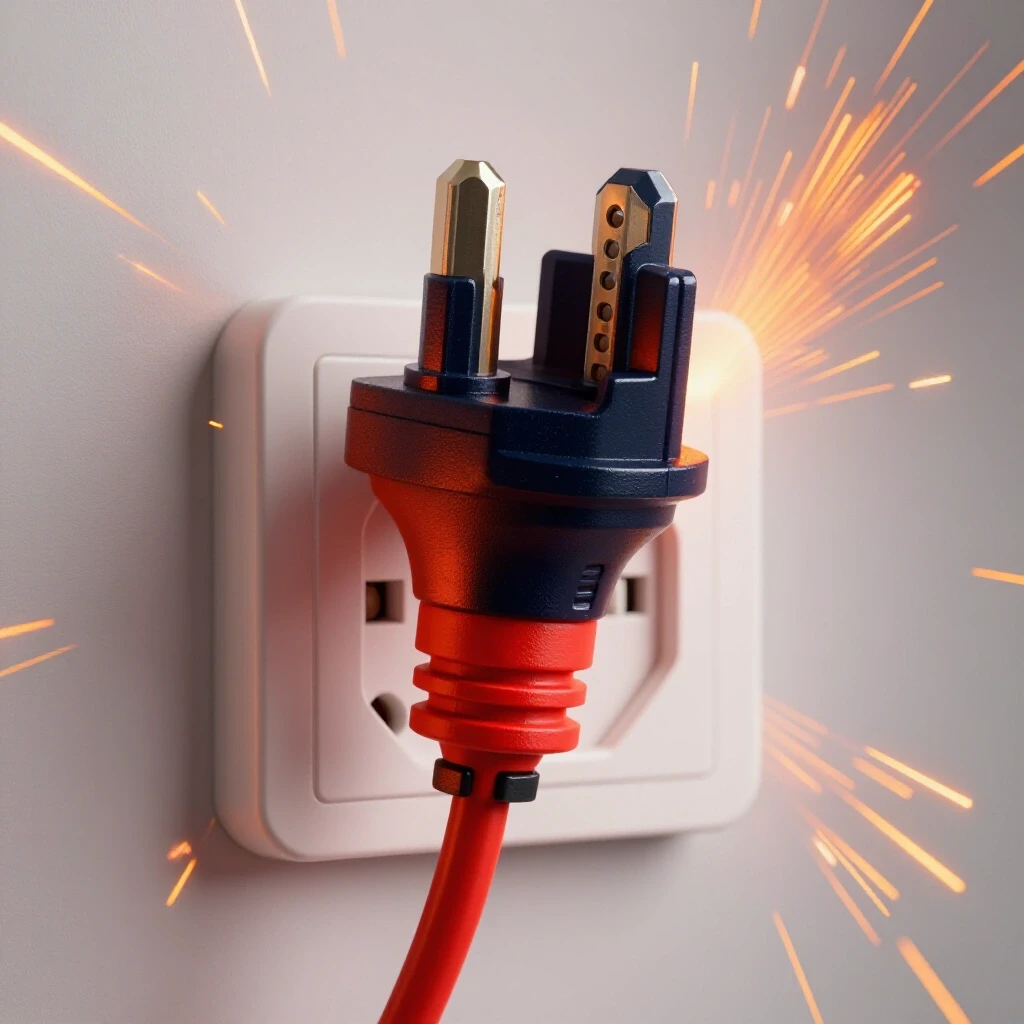
For most 240V welding applications in a dedicated shop setting, the NEMA 6-50 configuration is the industry standard. It is a three-wire setup: two hot legs and one ground. Unlike household dryer plugs (NEMA 14-30), which include a neutral wire for 120V timers and lights, a dedicated welder plug usually doesn’t need a neutral. This simplifies the wiring but requires absolute certainty in your grounding.
| Component | Specification | Purpose |
|---|---|---|
| Breaker | 50A Double-Pole | Provides 240V by tapping both bus bars in the panel. |
| Receptacle | NEMA 6-50R | Standard heavy-duty welder outlet. |
| Wire Color | Black/Red/Green | Black/Red are hot; Green is the dedicated safety ground. |
| Torque | 20-25 inch-lbs | Ensures a gas-tight electrical connection at the terminals. |
One common error I see is the use of “back-stab” or loose screw terminals. In high-vibration environments, or under the thermal expansion cycles of high-amperage welding, these connections loosen. A loose connection creates an arc, which creates carbon buildup, which increases resistance. This is a classic source of electrical metal fabrication fixes that people miss. Always use a torque screwdriver to meet the manufacturer’s specifications on the receptacle terminals.
Troubleshooting Weld Porosity Through Power Stability
Weld porosity is a defect characterized by tiny holes or pits in the weld bead, often caused by trapped gas or atmospheric contamination. While gas coverage is usually blamed, an unstable power supply can cause arc “stutters” that disrupt the shielding gas envelope. Ensuring a clean, dedicated power source is a vital diagnostic step for achieving X-ray quality welds.
When the voltage at the plug fluctuates, the transformer or inverter inside the welder struggles to maintain a constant current. This results in an inconsistent arc plasma. If the arc is jumping or fluttering, it can actually “pull” atmospheric air into the weld pool, regardless of your gas flow rate. I have seen fabricators spend hundreds on new regulators when the real issue was a loose ground in their 240V receptacle.
To diagnose this, I use a “load test.” While one person strikes an arc, another monitors the voltage at the outlet using a calibrated multimeter. If the voltage drops more than 3% (about 7 volts on a 240V line), the circuit is insufficient. This voltage drop is a silent killer of weld quality.
- Check for Voltage Drop: Measure at the panel, then at the outlet under load.
- Inspect Grounding: Ensure the ground wire is bonded directly to the panel’s ground bus.
- Verify Terminal Integrity: Look for discoloration or “bluing” on the copper wire, which indicates overheating.
Eliminating Tool Chatter and Motor Vibrations
Tool chatter is a resonant vibration that occurs during machining, resulting in a poor surface finish and reduced tool life. While often mechanical, chatter can be exacerbated by “dirty” power or phase imbalances that cause motors to run unevenly. A dedicated circuit minimizes the electrical noise that can trigger these harmful harmonics.
I once worked on a large lathe that had developed a harmonic vibration at 800 RPM. We checked the spindle bearings and the bed leveling, but the chatter remained. It turned out that the lathe was on a circuit shared with an old phase converter. The electrical “noise” from the converter was causing the lathe’s motor to “cog”—a tiny, rapid pulsing in torque. This pulsing matched the natural frequency of the workpiece, creating massive chatter.
By installing a dedicated line with a high-quality ground, we smoothed out the motor’s torque curve. In mechanical troubleshooting, we often look for physical play, but electrical “play” is just as real. A steady 240V supply ensures the motor provides constant torque, which is essential for maintaining the correct feed-per-tooth during heavy cuts.
- Spindle Backlash: 0.001 – 0.003 inches (Mechanical limit).
- Voltage Unbalance: Should be less than 1% between legs.
- Motor Torque Ripple: Can be induced by voltage sags.
Step-by-Step Diagnostic and Installation Process
This systematic approach focuses on the preparation, physical installation, and verification of a high-amperage shop circuit. It moves from planning the conduit path to the final testing of the voltage under load. Following a structured process reduces the risk of errors and ensures the installation meets safety and performance standards.
Phase 1: Mapping the Run
I start by measuring the distance from the main panel to the desired welder location. I prefer to keep the run as short as possible to minimize resistance. I use a 3/4-inch EMT conduit for a single 50-amp circuit. This provides plenty of “fill room” for three 6-AWG wires, which helps with heat dissipation.
Phase 2: Pulling the Conductors
When pulling wire, I never use “mystery” wire from a scrap bin. I use new THHN. I pull two “hot” wires (typically black and red) and one green ground wire. I avoid using the conduit itself as the sole ground. A dedicated copper ground wire is essential for the safety of the operator and the health of the machine’s electronics.
Phase 3: Terminating the Receptacle
I strip exactly 3/4 of an inch of insulation from the ends of the wires. I make sure no stray strands are sticking out. I hook the wires clockwise around the terminal screws of the NEMA 6-50R outlet. This ensures that as I tighten the screw, it pulls the wire tighter into the connection rather than pushing it out.
Phase 4: Verification and Testing
Before plugging in a $3,000 welder, I perform a sequence of tests: 1. Continuity Test: Ensure the ground is actually connected to the panel frame. 2. Voltage Test (No Load): Check for 240V across the two hots and 120V from each hot to ground. 3. Polarity Check: Ensure the hots are on the correct side terminals.
Case Study: The Case of the “Weak” Plasma Cutter
In 2019, I was called to a shop where a plasma cutter was failing to pierce 1/2-inch plate, despite being rated for 3/4-inch. The operator assumed the machine’s inverter was dying. We began a systematic diagnostic process. First, we checked the air supply—clean and dry at 90 PSI. Next, we checked the consumables—brand new.
I then measured the voltage at the wall. It read 238V at idle. However, the moment the arc initiated, the voltage plummeted to 204V. The machine was plugged into an old 30-amp circuit wired with 12-gauge wire that ran 100 feet across the ceiling. The wire was acting like a giant resistor.
We replaced the run with 6-AWG THHN in a dedicated conduit and installed a 50-amp breaker. The voltage drop under load improved to just 4 volts (234V). The plasma cutter immediately regained its full cutting capacity. This case highlights why “guessing” that a machine is broken can be a costly mistake. Always verify the power foundation first.
Electrical Diagnostic Checklist for the Fabricator
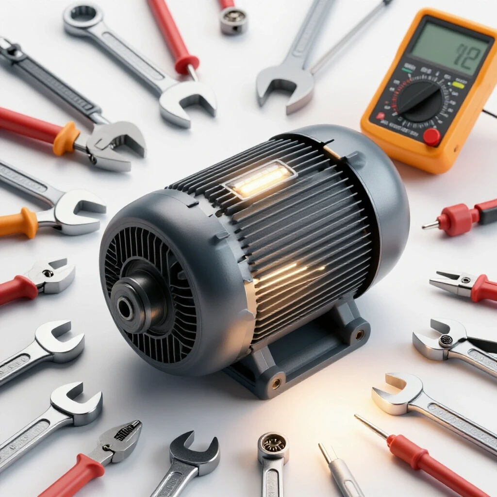
To maintain a high-performance shop, I recommend keeping a log of your electrical readings. This helps you identify trends before they become failures. Use a digital multimeter and an infrared thermometer for the most accurate data.
- Receptacle Temperature: After an hour of heavy welding, use an IR thermometer on the outlet face. If it exceeds 140°F (60°C), you have a loose connection.
- Voltage Drop Log: Record the idle voltage and the load voltage once every six months.
- Ground Impedance: Use a specialized meter to ensure your ground path has less than 25 Ohms of resistance (ideally much lower).
- Visual Inspection: Look for signs of “arcing” or soot inside the receptacle box.
- Breaker Snap: Periodically cycle the breaker to ensure the internal mechanism hasn’t seized from shop dust.
Conclusion: The Path to Precision
Mastering the infrastructure of your shop is just as important as mastering the torch or the mill. By installing a dedicated 240V circuit, you are removing a massive variable from your troubleshooting process. You no longer have to wonder if a weld defect is caused by a neighbor’s air conditioner or if a tool chatter issue is actually a motor torque ripple.
Systematic diagnostics require a stable baseline. A dedicated power drop provides that baseline. It allows you to focus on the mechanical and metallurgical aspects of your craft with the confidence that your equipment is receiving the clean, consistent energy it needs. My advice is simple: don’t build your shop on a “weak” foundation. Wire it right, torque it down, and get back to making sparks.
Frequently Asked Questions
Can I use a 30-amp dryer outlet for my welder? Most modern welders require 50 amps for full output. While a 30-amp circuit might work for light-duty hobby welding, it will likely trip the breaker during heavy penetration or long beads. Furthermore, dryer outlets (NEMA 14-30) have a different pin configuration than standard welder plugs (NEMA 6-50). Using adapters can lead to overheating at the connection points.
Why does my welder’s plug get hot during use? Heat is a symptom of resistance. This is usually caused by a loose wire terminal inside the plug or the receptacle. It can also be caused by oxidized copper wires or a “tired” receptacle that no longer has a tight spring-grip on the plug’s prongs. If it’s hot to the touch, stop immediately and tighten all connections or replace the receptacle.
Do I need a neutral wire for a 240V welder? Most dedicated 240V welders do not use a neutral wire. They use two “hot” legs to get the 240V and a “ground” for safety. However, some multi-process machines or those with internal 120V cooling fans might require a neutral (NEMA 14-50). Always check your machine’s manual before choosing your wire and plug type.
What is the difference between a ground and a neutral? A neutral wire is a “current-carrying” conductor that returns power to the panel in a 120V circuit. A ground wire is a “safety” conductor that should only carry current during a fault (like a short circuit). In a welder circuit, the ground protects you from the metal chassis of the machine becoming “live” if an internal wire fails.
Can I run my welder on an extension cord? It is not recommended for high-amperage use. Most extension cords are 12 or 10 gauge, which causes significant voltage drop over distance. If you must use one, it must be a heavy-duty 8-gauge or 6-gauge cord specifically rated for welding, and it should be as short as possible to prevent arc instability and overheating.
How do I know if my shop’s voltage is “dirty”? “Dirty” power refers to electrical noise or harmonics. You can identify this if your LED shop lights flicker when you weld, or if your CNC screen glitches. The best solution is a dedicated circuit for the welder and potentially a power conditioner or ferrite chokes for your sensitive electronics.
Is conduit necessary for shop wiring? In a metalworking environment, yes. Exposed cables (like Romex) are vulnerable to sharp metal off-cuts, hot slag, and heavy equipment. EMT conduit provides a grounded metal shield that protects the wires and prevents accidental fires if a wire is nicked.
What size breaker should I use for a 220V/240V welder? A 50-amp double-pole breaker is the standard for most workshop welders. This allows the machine to pull the high “inrush” current needed to start an arc without nuisance tripping. Always ensure your wire gauge (6 AWG) is rated to handle the breaker’s capacity.
Can a bad outlet cause weld porosity? Yes. If the outlet has a loose connection, the voltage to the welder will fluctuate. This causes the arc to “stutter.” When the arc is unstable, it fails to maintain a clean plasma column, allowing oxygen and nitrogen from the air to contaminate the weld pool, resulting in porosity.
What is the “duty cycle” and how does it affect my wiring? The duty cycle is the amount of time a welder can run at a specific amperage within a 10-minute period. While the NEC allows for smaller wires on machines with low duty cycles, I always recommend wiring for 100% duty cycle (6 AWG for 50A). This future-proofs your shop if you ever upgrade to a more powerful machine.
(This article was written by one of our staff writers, Paul Whitaker. Visit our Meet the Team page to learn more about the author and their expertise.)