How to Sequence Complex Frame Welds to Stop Warp (DIY Guide)
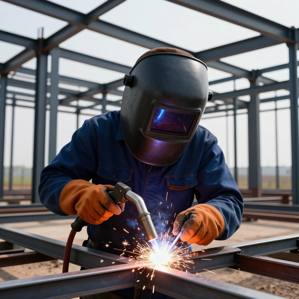
I have spent more than 20 years refining the way metal moves in my shop. In the early days, I approached fabrication with a “burn and turn” mindset, focusing more on the strength of the bead than the geometry of the finished product. I quickly learned that even the most beautiful weld is a failure if the frame it holds is pulled out of square by three-quarters of an inch. Transitioning from a hobbyist setup to a high-output production environment taught me that controlling heat is not just a skill—it is a systematic process. Whether I was building custom equipment trailers or complex machine bases, the struggle was always the same: managing the physics of cooling metal.
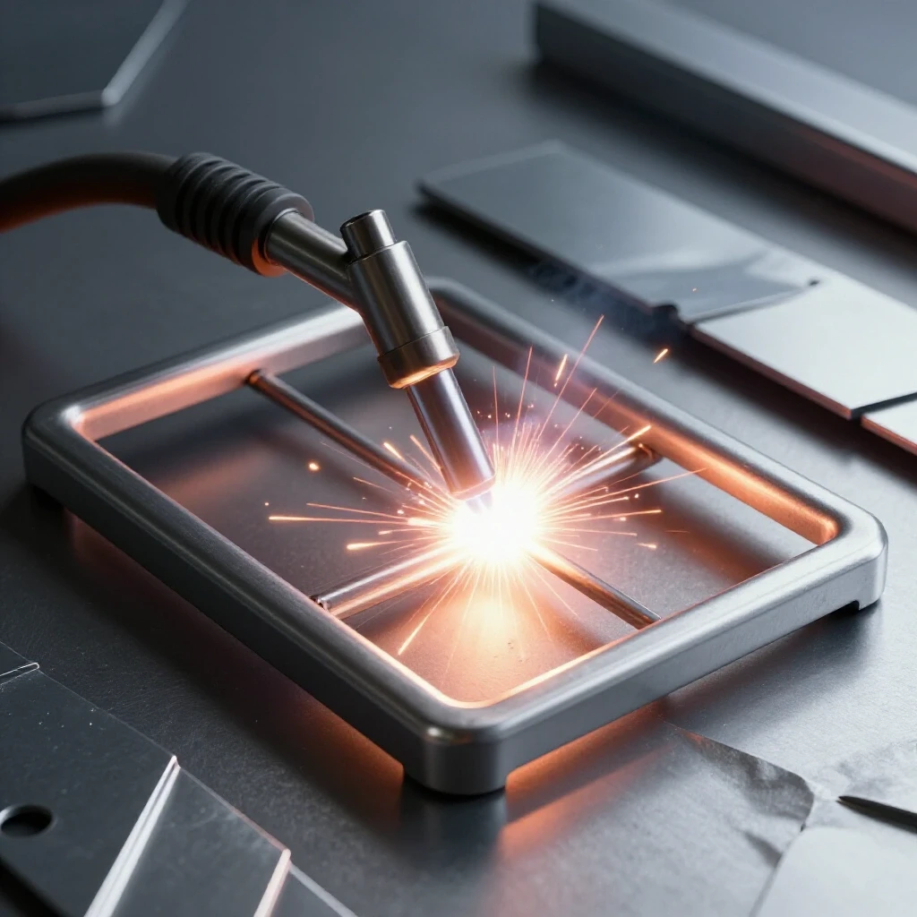
When you scale your operations, these errors become expensive. A warped frame means wasted material, hours of rework with a rosebud torch, and a significant hit to your shop’s throughput. I have seen advanced fabricators struggle with these same bottlenecks, often blaming their tables or their welders when the real culprit is the order of operations. To move into a semi-professional tier, you have to stop thinking about welding as joining two pieces and start thinking about it as managing a series of predictable, powerful contractions.
The Physics of Thermal Contraction in Steel Fabrication
Thermal contraction is the physical reduction in volume that occurs as molten metal cools and solidifies within a joint. When you apply heat to a specific area, the metal expands; as it cools, it shrinks. Because the weld is fused to the surrounding base metal, this shrinkage exerts a massive mechanical pull that can bend heavy tubing and plate.
Understanding why steel moves requires looking at the heat-affected zone (HAZ). When we weld, we aren’t just adding filler; we are creating a localized area of extreme temperature. As the bead cools, it acts like a tightening rubber band. If all your “rubber bands” are pulling in the same direction, your frame will bow. In my shop, I treat every weld as a vector of force. If I put a force on the top left of a chassis, I must find a way to counter that force on the bottom right, or at least distribute the tension so it doesn’t accumulate into a visible warp.
- Expansion: Metal grows as it gets hot, often pushing joints out of alignment before the weld is even finished.
- Contraction: As the puddle freezes, it shrinks roughly 1% to 3% in volume, pulling the connected members toward the center of the weld.
- Leverage: The further a weld is from the neutral axis of a part, the more leverage it has to bend that part.
Strategic Workflow Mapping for Distortion Control
Workflow mapping for distortion control involves planning the exact order of every weld on a project before the arc is even struck. This systematic approach ensures that heat is distributed evenly across the entire structure, preventing any single area from reaching a critical temperature that leads to permanent structural shifting.
In a professional manufacturing environment, we don’t just start at one end of a frame and work to the other. That is a recipe for a banana-shaped project. Instead, I use a “center-out” or “balanced-pair” approach. If I am working on a 10-foot ladder frame, I might tack the entire assembly first, then weld the center cross-member, then move to the outermost ends. By jumping around the project in a planned sequence, I allow one area to cool and stabilize while I am adding heat to another. This prevents the “compounding pull” effect where each successive weld adds to the tension of the previous one.
Comparison of Welding Sequences
| Sequence Type | Heat Distribution | Risk of Warpage | Ideal Application |
|---|---|---|---|
| Progressive (End-to-End) | Poor | Very High | Short, non-critical joints |
| Center-Out | Moderate | Medium | Square frames and plates |
| Balanced Skip | Excellent | Low | Long chassis, thin-wall tubing |
| Back-Stepping | Superior | Very Low | High-precision structural seams |
Implementing the Skip Welding Technique
Skip welding is a method where short increments of weld are placed at intervals along a seam, leaving gaps that are filled in later. This technique limits the total amount of heat concentrated in one section of the metal at any given time, which significantly reduces the internal stresses that cause twisting and bowing.
I often use skip welding when I am dealing with long runs of square tubing. If I have a four-foot seam, I won’t run it in one pass. I will weld two inches at the start, move to the middle for two inches, and then move to the end. By the time I come back to fill the gaps, the first welds have already gone through their initial contraction phase. Interestingly, this also helps with air quality in the shop; by not saturating the metal with heat, you reduce the amount of secondary off-gassing from mill scale or coatings nearby.
- Divide the total seam into equal segments (e.g., 2-inch increments).
- Weld segment 1, 3, and 5 first.
- Allow the material to return to a temperature where you can comfortably touch it with a gloved hand.
- Return to weld segments 2, 4, and 6.
The Role of Back-Stepping in Seam Management
Back-stepping is a sequencing technique where the direction of the weld bead travel is opposite to the overall direction of the seam’s progress. While the welder moves from left to right along the frame, each individual bead is actually laid down from right to left, which helps to “lock” the metal in place as the work proceeds.
This is one of the most counter-intuitive but effective tools in my arsenal. Imagine you are welding a long butt joint on a flat sheet. If you weld continuously from left to right, the heat builds up ahead of the puddle, expanding the gap and then pulling it tight as it cools, often resulting in an overlapping or “oil-canning” effect. When you back-step, each new bead terminates into a previously cooled, hardened weld. This acts as a mechanical anchor, preventing the plates from sliding or pulling toward the heat.
- Step 1: Start your first bead two inches in from the edge and weld toward the edge.
- Step 2: Start your second bead four inches in and weld toward the start of the first bead.
- Step 3: Continue this pattern until the entire seam is closed.
Utilizing Balanced Welding Around the Neutral Axis
Balancing welds around the neutral axis refers to the practice of placing equal amounts of weld metal on opposite sides of a structural member’s center of gravity. By mirroring the heat input, the contraction forces on one side of the part are cancelled out by the contraction forces on the other side.
In my experience with heavy equipment frames, ignoring the neutral axis is the fastest way to ruin a build. If you weld the top flange of an I-beam but ignore the bottom, that beam will arch upward. When I am working on a box-section frame, I always weld in pairs. If I weld the “outside” vertical seam of a corner, my next move is to weld the “inside” vertical seam of that same corner. This creates a tug-of-war where neither side wins, leaving the part straight.
Heat Input and Material Thickness Metrics
| Material Thickness | Max Bead Length (Inches) | Recommended Cooling Time |
|---|---|---|
| 16 Gauge (0.060″) | 0.5 – 1.0″ | 3-5 Minutes |
| 1/8″ (0.125″) | 1.5 – 2.0″ | 2-4 Minutes |
| 3/16″ (0.187″) | 2.5 – 3.0″ | 1-2 Minutes |
| 1/4″ (0.250″) | 4.0″+ | Minimal |
The Critical Importance of Tack Welding and Fixturing
Tack welding and fixturing involve the use of small, temporary welds and mechanical restraints to hold components in a fixed position during the final welding process. These tools act as the primary defense against the initial forces of thermal expansion that occur as soon as the arc is struck.
I cannot emphasize enough how much a heavy, flat welding table changes the game. In my shop, I transitioned from sawhorse setups to a dedicated 5/8-inch thick platen table. This allows me to use “intermittent clamping,” where I secure the frame to the table’s mass. The table acts as a giant heat sink, pulling thermal energy out of the tubing faster than the air can. However, you must be careful. If you clamp a frame too tightly and weld it solid, it may still warp the moment you release the clamps because the internal stresses are still there. The key is to use the clamps to hold the geometry while using the sequence to manage the stress.
- Tack size: Tacks should be deep and functional, roughly 2-3 times the thickness of the material in length.
- Tack placement: Place tacks at all corners first, then at the midpoints of long spans.
- Clamp pressure: Use enough pressure to prevent movement, but avoid “pre-loading” or bending the tube with the clamp itself.
Managing Interpass Temperature in Multi-Pass Welds
Interpass temperature management is the process of monitoring and controlling the temperature of the base metal between successive welding passes. Keeping the material within a specific temperature range prevents the accumulation of excessive heat that leads to large-scale structural distortion and changes in the metal’s grain structure.
When you are scaling up to semi-professional work, you might find yourself doing multi-pass fillets on thicker brackets. If the metal gets too hot, it loses its structural integrity and becomes much more prone to moving. I use infrared thermometers to check the heat. If the steel exceeds 400 or 500 degrees Fahrenheit between passes, I stop. I might move to a different part of the frame or use a fan to move air across the joint. This is a great time to focus on other shop tasks, like organizing material flow or checking your gas levels.
- Establish a maximum allowable interpass temperature based on the steel grade.
- Use temp-sticks or infrared sensors to verify the heat before starting the next bead.
- If the part is too hot, allow it to air-cool naturally; quenching with water can cause embrittlement.
Designing a Welding Station for Efficient Material Flow
A welding station designed for material flow optimizes the physical layout of tools, tables, and raw stock to minimize unnecessary movement and maximize the fabricator’s ability to reach all sides of a project. This layout is essential for maintaining a consistent welding sequence without being hindered by shop clutter.
In my workshop, I realized that I was often breaking my welding sequence simply because I couldn’t reach the other side of the table without tripping over a lead or a scrap bin. This leads to “lazy welding,” where you stay in one spot and weld everything you can see, which is the worst thing for warp control. I reorganized my layout to ensure a 3-foot minimum access zone around the main welding platen. I also integrated overhead booms for the MIG gun leads and grinders. This keeps the floor clear and allows me to move from one side of a 12-foot frame to the other in seconds, keeping my heat-balancing sequence on track.
- Zoning: Keep the “dirty” grinding area separate from the “clean” welding table to prevent grit from entering your joints.
- Power Access: Ensure your 240V or 3-phase outlets are positioned so leads don’t cross the main walking paths.
- Lighting: High-output LED shop lights are critical for seeing the fit-up gaps that contribute to uneven draw.
Common Mistakes in Frame Fabrication Sequencing
Even experienced fabricators fall into traps that lead to warped assemblies. One of the most common errors is “over-welding.” We often feel that if a 2-inch weld is good, a 6-inch weld is better. In reality, adding more weld metal than the design requires only adds more heat and more contraction force. Another mistake is ignoring the “fit-up.” If you have a 1/8-inch gap on one side of a joint and a tight fit on the other, the side with the gap will shrink significantly more as the weld fills that void.
- Inconsistent Gaps: Always aim for a uniform fit-up. Use spacers or feeler gauges if necessary.
- Welding into Corners: Avoid starting or stopping your welds exactly in the corner of a frame. This creates a stress riser and makes it harder to balance the pull.
- Ignoring the Tack Order: Tacking from one end to the other can “walk” the frame out of square before you even start the main beads. Always tack in a criss-cross pattern.
Advanced Tools for Tracking and Verification
As you move toward a more professional operation, you should start documenting what works. I keep a “Weld Log” for complex frames. I note the sequence I used and measure the frame’s squareness before and after. This data-driven approach takes the guesswork out of the next build. If a specific sequence resulted in a 1/16-inch bow, I know I need to add more skip-welds or change my clamping pressure next time.
- Digital Angle Finders: Used to check for “twist” across the length of long rails.
- String Lines: A simple, old-school way to check for bowing over 10 to 20 feet.
- Weld Sequence Sheets: A printed diagram of the frame where I number each weld to ensure I follow the plan.
Frequently Asked Questions
How do I know which side of a joint to weld first?
Start with the side that is most likely to pull the part into square. If your frame is slightly wide at the top, weld the inside corners first to pull them together. Always analyze the existing geometry and use the natural contraction of the weld to your advantage.
Can I use water to cool the welds faster and stop warp?
I strongly advise against this. Rapid cooling with water (quenching) can make the steel brittle and cause “underbead cracking.” It also doesn’t stop the initial contraction; it only speeds up the cooling of a part that has already moved. Air cooling is the safest way to maintain the material’s properties.
Does the type of welding process affect the amount of warp?
Yes. Processes with higher energy density, like TIG, often result in more localized heat but can cause significant distortion if you move slowly. MIG is generally faster and can result in less total heat input if the settings are optimized. However, the sequence is always more important than the process itself.
How many tacks are enough for a 4-foot frame?
For a 4-foot square tubing frame, I typically place a tack at every corner, then one every 12 inches along the span. These tacks should be strong enough to resist the pull of the first few inches of the main weld. If a tack pops, your sequence is compromised.
What is the best way to fix a frame that has already warped?
The best method is “flame straightening,” where you use an oxy-acetylene torch to heat the side opposite the warp. As that spot cools, it shrinks and pulls the frame back. It is a slow, surgical process that requires a lot of patience and practice.
Should I weld the top and bottom of a tube, or the sides first?
Always weld the sides (the vertical webs) first. These provide the most structural stiffness. If you weld the top and bottom (the flanges) first, the tube is more likely to bow up or down because there is less vertical resistance.
How does material thickness change the sequencing strategy?
Thinner materials (under 1/8 inch) require much shorter weld increments and longer cooling periods. Thicker materials (1/4 inch and up) can handle more heat, but the contraction forces are much stronger, requiring heavier fixtures and more robust tacks.
Can I use a heavy weight to hold a frame flat?
Weights can help, but they are less effective than mechanical clamps. A weight only provides downward force, whereas a clamp “locks” the part to the table, resisting forces in multiple directions.
Why does my frame always twist like a propeller?
Twisting is usually caused by an asymmetrical welding sequence. If you weld all the top-left and bottom-right corners first, you are creating a rotational force. Ensure you are mirroring your welds across both the X and Y axes of the frame.
Is it better to weld the inside or outside of a corner first?
I prefer welding the outside corner first. This “locks” the outer dimensions of the frame. If you weld the inside first, the contraction can pull the corners “in,” making the overall frame smaller than your intended measurement.
How long should I wait between welds in a skip sequence?
Wait until the previous weld has changed from a “glowing” or “blue” heat to a dull grey, and the surrounding metal is cool enough to touch briefly with a gloved hand. This usually takes 2 to 4 minutes depending on the ambient temperature.
Does the direction of the weld (push vs. pull) affect warp?
While the direction affects penetration and bead profile, its impact on warp is secondary to the sequence. However, “pulling” (dragging) the puddle often puts slightly more heat into the base metal, which can marginally increase distortion compared to “pushing.”
(This article was written by one of our staff writers, Edward Sinclair. Visit our Meet the Team page to learn more about the author and their expertise.)