How to Set Feeds and Speeds for CNC Cutters (DIY Guide)
The transition from a hobbyist workspace to a high-output fabrication shop is rarely a smooth line. It is usually a series of jagged steps, each marked by a new machine, a revised floor plan, or a hard lesson learned in electrical loading. After twenty years of refining my own manufacturing operations, I have found that the biggest hurdle isn’t just buying a CNC machine. The real challenge lies in integrating that machine into a system where material flows logically, power is stable, and the tool itself moves at the precise rate required to produce clean parts without breaking bits.
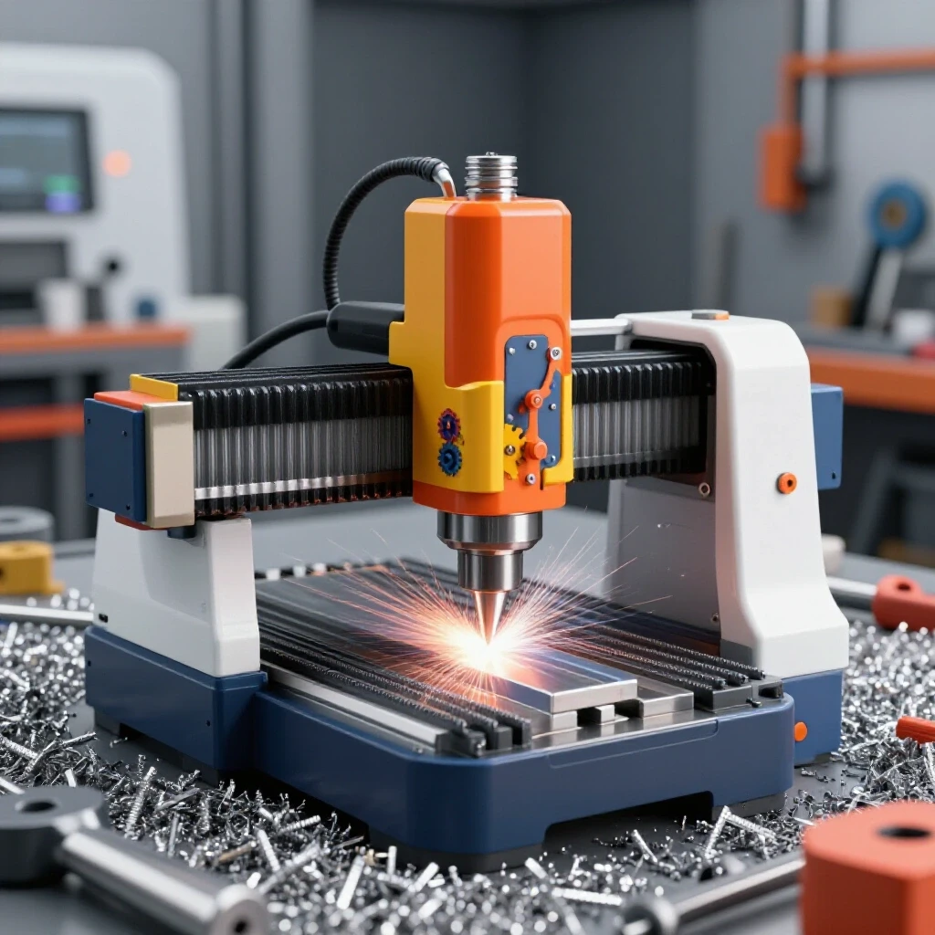
When I first added a CNC gantry to my setup, I treated it like a standalone tool. That was a mistake. A CNC system is the heart of a workflow, and it demands a specific environment to function at its peak. You have to think about how raw sheets enter the building, how the machine receives balanced power, and how the waste is removed. If any of these links are weak, your expensive new automation will simply become a very fast way to make scrap metal.
Mapping Material Flow to Eliminate Shop Bottlenecks
Advanced workshop layout is the practice of positioning machinery and material storage to minimize unnecessary movement. By analyzing the path a piece of steel or aluminum takes from the delivery truck to the shipping crate, you can identify “spaghetti paths” that waste time and energy.
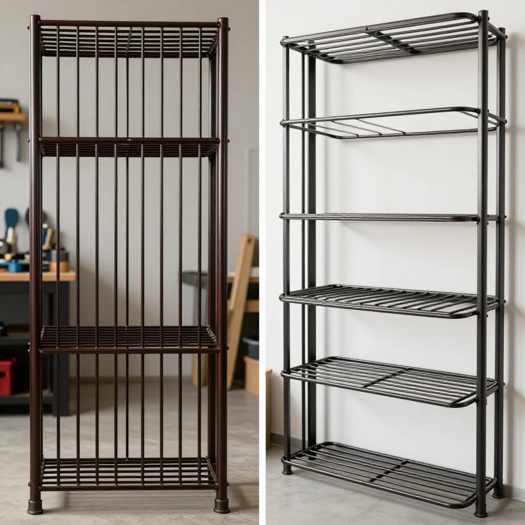
In my early years, I spent more time moving material than actually cutting it. I would haul a 4×8 sheet of plywood or steel across the entire shop, dodging the welder and the assembly table, just to get it to the saw. This is what lean manufacturing calls “motion waste.” To fix this, I redesigned my floor plan into a linear flow. Now, material enters through the rear bay, sits in a vertical rack immediately adjacent to the CNC table, and moves forward toward the deburring and finishing stations.
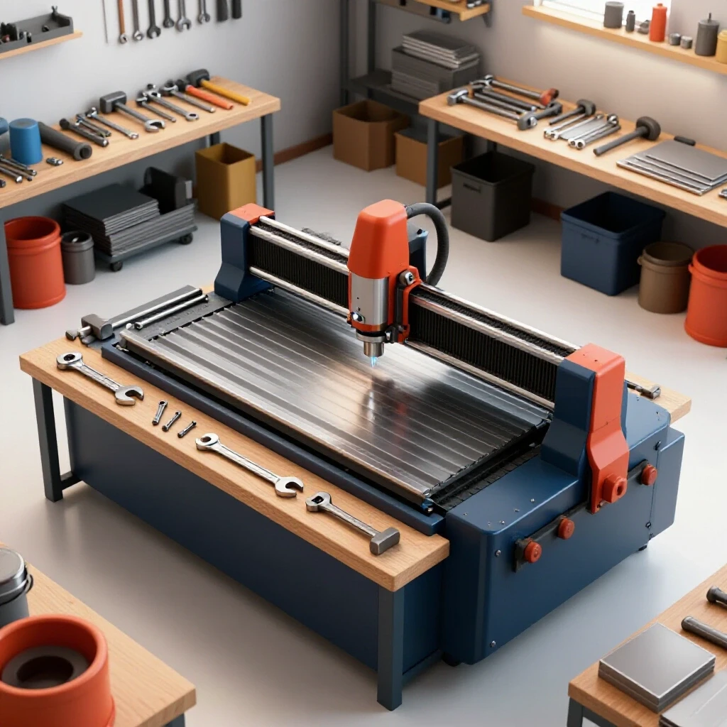
When planning your layout, consider the “3-foot rule.” Every major machine needs a minimum of three feet of clear access on all sides for maintenance and safety. For a CNC plasma table setup or a milling gantry, you also need to account for the “swing zone” of material handling. If you are using a jib crane or a vacuum lift to load the bed, that radius must be completely clear of overhead lights, heaters, or air lines.
| Layout Style | Material Travel Distance | Efficiency Rating | Best For |
|---|---|---|---|
| Random Placement | High (Variable) | Low | Occasional Hobby Use |
| U-Shaped Flow | Moderate | High | Small Footprint Shops |
| Linear (Straight) | Low | Very High | High-Volume Production |
| Cellular Design | Minimal | High | Specific Product Families |
Establishing a Reliable 3-Phase Power Foundation
A 3-phase power converter is a device that transforms standard single-phase residential or light commercial electricity into the three-leg power required by industrial motors. This setup provides more consistent torque and higher efficiency for heavy-duty CNC spindles and large air compressors.
Most home-based shops are limited by a 200-amp single-phase service. When you start adding 5HP or 10HP spindles, your electrical demand can cause voltage drops that crash sensitive CNC controllers. I learned this the hard way when my spindle bogged down during a heavy cut, causing the stepper motors to lose steps and ruin a $400 slab of 6061 aluminum.
I eventually installed a Rotary Phase Converter (RPC). An RPC uses a physical idler motor to generate the third leg of power. It is robust and handles the “inrush” current of starting a large motor better than most low-cost static converters. If you are scaling up, check your National Electrical Code (NEC) requirements for grounding. A “dirty” ground can introduce electrical noise into your signal wires, leading to “ghost” movements in your CNC gantry.
- Rotary Phase Converters: Best for running multiple machines; provides a true 3-phase sine wave.
- Variable Frequency Drives (VFDs): Excellent for controlling the speed of a single spindle; provides soft-start capabilities.
- Digital Phase Converters: The most expensive option, but offers the cleanest power for sensitive electronics.
Designing High-Volume Clean Air Filtration Systems
Dust collection duct design involves calculating the volume of air (CFM) and the resistance (static pressure) required to pull debris away from the cutting tool. A professional-grade system ensures that fine particulates are captured before they settle on precision rails or enter your lungs.
In a CNC environment, air quality isn’t just about sawdust. If you are cutting plastics or composite boards, the “fines” can be abrasive and even explosive. I designed my current system using 6-inch rigid metal ducting. Unlike flexible ribbed hose, smooth-wall pipe reduces friction. Every 90-degree turn in a flexible hose can be equivalent to adding 10 feet of straight pipe in terms of air resistance.
You should aim for an air velocity of at least 4,000 feet per minute (FPM) in your branch lines to keep chips moving. If the air moves too slowly, the chips will drop out of the airstream and clog your pipes. I use a multi-stage cyclone separator. The cyclone drops the heavy chips into a drum, while the fine 1-micron filters catch the dust that actually causes respiratory issues.
- Calculate Total CFM: Sum the requirements of your largest tools. A CNC gantry usually needs 600–800 CFM at the hood.
- Measure Static Pressure: Account for the length of the run and the number of bends.
- Select a Blower: Choose a fan curve that meets your CFM needs at your calculated static pressure.
- Install Blast Gates: Use automated or manual gates to concentrate suction only on the tool in use.
Mastering the Math of Tool Movement
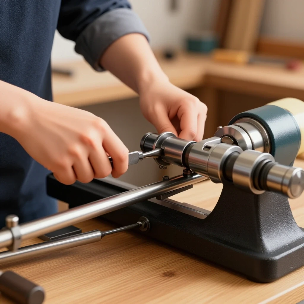
Calculating the optimal rotation speed and travel velocity of a milling bit is a foundational skill for any fabricator moving into automation. This process involves balancing the tool’s diameter, the material’s hardness, and the number of cutting edges to ensure the tool carves rather than rubs.
When I first started, I thought faster was always better. I would crank the spindle to its maximum RPM and hope for the best. The result was usually a bluing of the tool and a melted mess of plastic. The key is understanding “Surface Feet per Minute” (SFM). This is the actual speed at the outer edge of the tool as it spins. A 1/4-inch bit spinning at 10,000 RPM is moving much slower at its edge than a 1/2-inch bit at the same RPM.
To find the correct spindle speed, you use a simple formula: RPM = (SFM x 3.82) / Tool Diameter. The SFM value comes from a material chart. For example, mild steel might have an SFM of 100, while aluminum can be as high as 600–1,000 for DIY-grade machines. Once you have the RPM, you must determine how fast the machine should move across the material, known as the feed rate.
Determining the Ideal Chip Load for Material Removal
Chip load is the thickness of the material flake that each individual cutting edge (flute) of the tool removes during one revolution. Maintaining the correct chip load is vital because the chip carries away the heat generated during the cut.
If your chip load is too small, the tool will “rub” against the material. This creates friction and heat, which dulls the tool rapidly. If the chip load is too large, you put excessive force on the tool, which can lead to snapping or “chatter”—a vibration that leaves a poor surface finish. I always tell people to look at their chips. You want actual chips, not dust.
The formula for the travel speed is: Feed Rate = RPM x Number of Flutes x Chip Load. For a two-flute 1/4-inch end mill in aluminum, you might target a chip load of 0.002 inches. If your calculated RPM is 10,000, your feed rate would be 40 inches per minute (IPM).
- Aluminum: High SFM, moderate chip load. Needs clearing to prevent “welding” to the bit.
- Mild Steel: Low SFM, heavy chip load. Requires high torque and rigid setups.
- Brass: Moderate SFM, small chip load. Can be “grabby,” so use specialized bits.
- Plastics: High SFM, very high chip load. The goal is to cut the plastic before it melts.
Iterative Testing and the “Ear” Method
No formula is perfect because every shop has different variables. The rigidity of your CNC gantry, the quality of your collets, and even the way you clamp your workpiece all affect the outcome. I recommend starting at 80% of the calculated feed rate and gradually increasing it.
Listen to the machine. A healthy cut has a consistent, crisp sound. A high-pitched scream usually means your RPM is too high for the feed rate (rubbing). A low-growing vibration or “chug” often means you are pushing too hard or your depth of cut is too deep. I keep a logbook next to my controller. Every time I run a new material, I record the settings and the result. Over time, this becomes a custom tool library that is far more accurate than any generic chart.
Integrating CAD/CAM Workflows for Efficiency
Workflow optimization tips often focus on the physical, but the digital side is where the most time is lost. Software integration is the bridge between your design and the physical movement of the tool. Modern CAM (Computer-Aided Manufacturing) software allows you to build a virtual tool library.
In my shop, I have pre-configured “tool templates” for every material I stock. When I design a part, I simply apply the “1/4-inch Aluminum” template, and the software automatically populates the RPM, feed rates, and ramp-in speeds. This reduces the “setup time” bottleneck. Instead of recalculating the math every morning, I can go from a drawing to a finished part in minutes.
- Define Tool Geometry: Enter the exact diameter and flute length of your bits.
- Set Step-Down Limits: Determine how deep the tool can cut in a single pass (usually 50% of the tool diameter).
- Configure Lead-ins: Use “ramping” to move the tool into the material at an angle rather than plunging straight down.
- Simulate the Path: Always run a software simulation to check for collisions with clamps or fixtures.
Managing Capital Costs and Amortization
Scaling a fabrication shop requires an honest look at the numbers. Every upgrade, from a 3-phase converter to a multi-stage dust collector, must pay for itself through increased throughput or reduced labor. I use a simple amortization schedule to track these costs.
If a $5,000 CNC upgrade saves you 5 hours of manual grinding per week, and your shop rate is $75/hour, the machine pays for itself in about 13 weeks. However, you must also factor in maintenance. CNC systems require regular lubrication of the lead screws, filter changes in the control box, and occasional replacement of the sacrificial “spoil board” on the table.
| Investment Item | Estimated Cost | Lifespan | Primary Benefit |
|---|---|---|---|
| Rotary Phase Converter | $800 – $2,500 | 15+ Years | Industrial Power Stability |
| Cyclone Dust Collector | $1,200 – $4,000 | 10+ Years | Air Quality & Tool Life |
| CNC Gantry System | $5,000 – $25,000 | 5-8 Years | Automated Precision |
| Rigid Ducting Network | $500 – $1,500 | 20+ Years | Efficient Debris Removal |
Transitioning to Semi-Professional Operations
The move toward a professional-grade shop is as much about mindset as it is about machinery. It requires moving away from the “one-off” mentality and toward repeatable systems. This means labeling your 3-phase circuits, documenting your air filter maintenance intervals, and standardizing your cutting parameters.
One of the best things I did was install a “smart” monitor for my shop’s power usage. It allows me to see exactly how much energy the CNC is drawing during a heavy cut. This data helped me realize that my old air compressor was cycling too frequently, causing voltage sags. By adding a secondary air tank (a “surge tank”), I leveled out the load and improved the consistency of my CNC plasma table setup.
Practical Benchmarks for Shop Success
As you refine your space, aim for these specific metrics to ensure you are on the right track. These are not arbitrary numbers; they are based on industrial safety and efficiency standards that I have applied in my own facility.
- Machine Spacing: Keep at least 36 inches of clearance around all electrical panels.
- Air Velocity: Maintain 4,000 FPM in dust ducts to prevent clogging.
- Phase Balance: Ensure the voltage between the three legs of your power is within 5% of each other.
- Material Buffer: Keep at least 20% of your floor space open for material staging and movement.
- Tooling Life: If you are breaking more than one bit per 50 hours of cutting, re-evaluate your feed and speed calculations.
Summary of Next Steps
Start by mapping your current material flow. Take a piece of chalk and draw the path you take to make a common part. If it looks like a spider web, it’s time to reorganize. Once the floor is clear, look at your power. If you are still running heavy spindles on single-phase circuits, research a rotary phase converter to stabilize your torque.
Next, address the air. A clean shop is a productive shop. Design a rigid ducting system that matches the CFM requirements of your CNC gantry. Finally, dive into the math of tool movement. Use the SFM and chip load formulas to create a custom tool library. This data-driven approach will remove the guesswork and give you the confidence to push your shop to the next level of production.
Frequently Asked Questions
How do I know if my shop floor can handle a heavy CNC machine? Most residential garage floors are 4 inches thick, which can support about 3,000 to 4,000 PSI. For large CNC milling machines, you may need a 6-inch reinforced pad to prevent the floor from cracking or the machine from losing level over time.
What is the difference between a stepper motor and a servo motor for CNC? Stepper motors move in fixed increments and are more affordable, but they can “lose steps” if they hit an obstruction. Servo motors use a closed-loop feedback system (encoders) to constantly report their position, making them more reliable for high-speed, professional work.
Can I use a shop vac for my CNC dust collection? A shop vac has high suction (static pressure) but very low air volume (CFM). It is okay for a tiny benchtop machine, but for a full-sized gantry, you need a dedicated dust collector that can move at least 600–800 CFM to capture fine particulates.
Why does my 3-phase converter hum so loudly? A rotary phase converter is essentially a large motor running constantly. The hum is normal, but it can be minimized by mounting the converter on vibration-damping pads and housing it in a ventilated, sound-dampened enclosure.
How often should I change the filters in my shop’s air scrubbing system? In a high-production environment, check your primary filters monthly. If you notice a drop in suction at the tool (measured with a pitot tube or manometer), it’s time to clean or replace the filters.
What is “climb milling” vs. “conventional milling”? Climb milling is when the tool rotates with the direction of the feed. It generally produces a better surface finish and longer tool life on CNC machines. Conventional milling is the opposite and is often used on older, manual machines with a lot of “backlash” or play in the gears.
How do I calculate the “stepover” for a 3D carving? Stepover is the distance the tool moves over for the next pass. For a smooth finish, a stepover of 8% to 10% of the tool diameter is common. For roughing out material quickly, you can go up to 40% or 50%.
Is 3-phase power really necessary for a small shop? If you plan to run industrial-grade spindles or large compressors, yes. 3-phase power is more efficient, leads to cooler-running motors, and provides the consistent torque needed for heavy material removal.
What are the signs of a “rubbing” tool? Look for smoke, a high-pitched squealing sound, or a “discolored” edge on the material. If the chips look like fine dust rather than distinct flakes, your feed rate is likely too low for your spindle RPM.
How do I manage the high learning curve of CAM software? Start with simple 2D shapes and focus on mastering one material at a time. Use the simulation features extensively to catch errors before you ever turn on the machine. Many advanced users find that “YouTube University” and manufacturer-specific forums are the best resources for troubleshooting specific software quirks.
(This article was written by one of our staff writers, Edward Sinclair. Visit our Meet the Team page to learn more about the author and their expertise.)