How to Speed Up Welding Joint Prep Time Safely (DIY Guide)
I remember standing in a cold shop three years ago, staring at a pile of 1-inch thick plate steel that needed to be beveled, cleaned, and tacked by the end of the day. Every time I touched my grinder to the metal, the vibration was so intense it felt like my fillings were going to shake loose. The finish was wavy, the edges were inconsistent, and I knew that if I didn’t solve the prep issue, the actual welding would be a nightmare of slag inclusions and poor penetration.
Efficiency in a fabrication shop isn’t just about moving faster; it is about reducing the friction between your raw material and a finished, high-quality weld. When we talk about streamlining the steps before the arc is even struck, we are really talking about systematic diagnostic work. If your tools are vibrating, your surface is contaminated, or your fit-up is sloppy, you will spend three times as long fixing the weld as you did preparing the joint. Over my 15 years as a millwright and fabricator, I have learned that the fastest way to finish a job is to ensure the mechanical and metallurgical foundations are solid from the start.
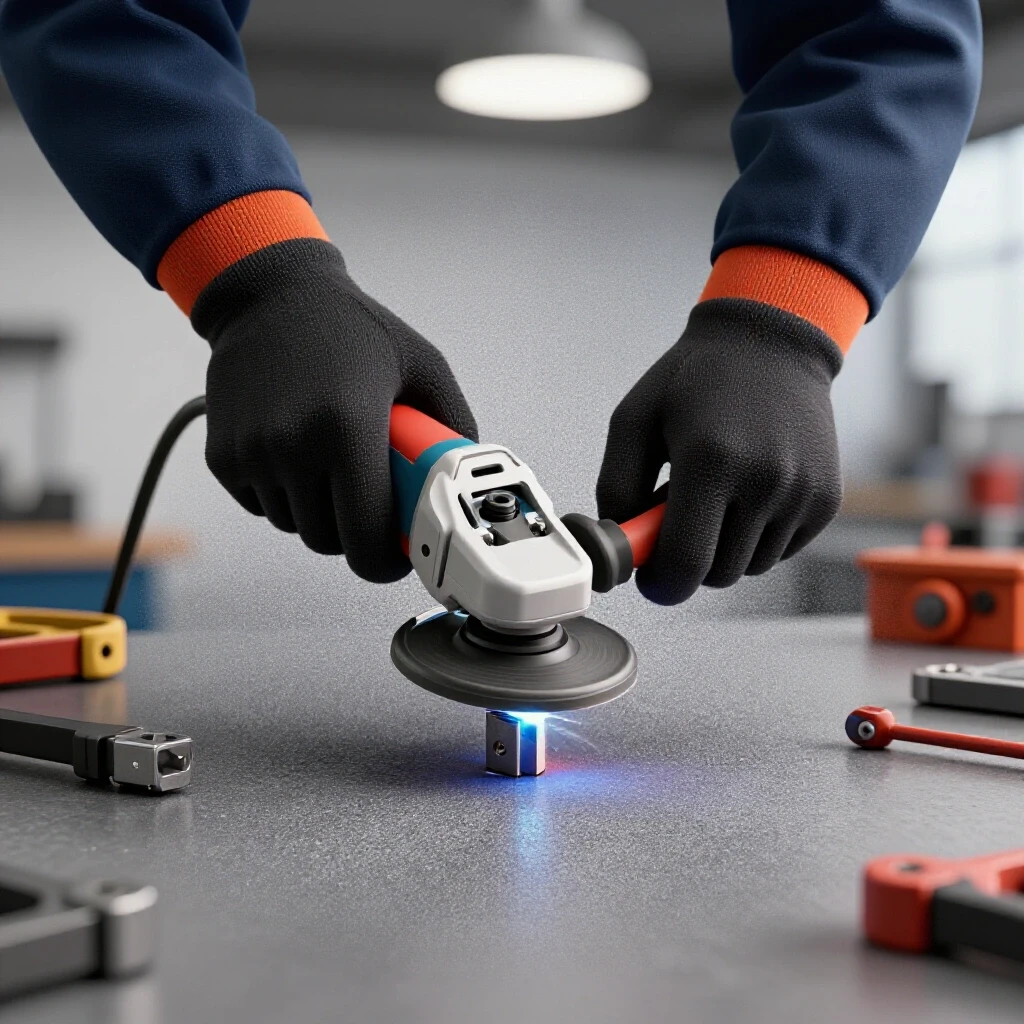
Establishing a Systematic Framework for Pre-Weld Efficiency
A systematic framework for metal preparation involves organizing your workspace, tools, and material flow to eliminate wasted movement and ensure every mechanical action produces a predictable result. This process identifies bottlenecks in the workflow and treats the preparation phase as a precise engineering task rather than a chore.
In my experience, most time is lost not during the grinding itself, but in the “walking waste”—the time spent looking for the right abrasive, adjusting a poorly maintained tool, or re-cleaning a surface that was contaminated by a dirty glove. To speed up your process, you must first audit your current state. Start by timing how long it takes to prepare a standard 4-foot joint. If you are spending more than 15 minutes on cleaning and beveling that length in a DIY environment, there is a mechanical or procedural error in your chain.
I use a “Rule of Three” for my diagnostic path. First, I check the tool’s mechanical health. Second, I evaluate the abrasive-to-material match. Third, I inspect the environment for contamination risks. If any of these are off, the speed of the operation drops significantly. For example, a grinder with a worn-out bearing won’t just be loud; it will cause the disc to bounce, which creates “chatter” marks on the steel. These marks trap air and debris, leading to porosity that you will have to grind out later.
Diagnosing Tool Chatter and Vibrational Harmonics
Tool chatter is a resonant vibration that occurs when the frequency of the tool’s movement matches the natural frequency of the workpiece or the tool’s own internal components. This creates a rhythmic bouncing effect that ruins surface finishes and accelerates tool wear, making it impossible to achieve a clean weld interface quickly.
When I encounter excessive vibration while beveling an edge, I don’t just grip the grinder tighter. I look for the root cause. Often, it is a matter of spindle backlash or an unbalanced mounting flange. Backlash is the amount of “play” or clearance between mating gear teeth in a tool’s gearbox. If your grinder has more than 0.005 inches of play in the spindle, the disc will not rotate in a perfect plane. This wobble introduces lateral forces that fight your hands and slow down your metal removal rate.
To isolate this, I perform a simple run-out test. With the tool unplugged, I use a dial indicator against the mounting flange. If the needle jumps more than a few thousandths, the tool is a liability. Another common culprit is “harmonic resonance” in the workpiece. If you are prepping a long, thin strip of metal that isn’t clamped properly, the metal itself will vibrate like a tuning fork. This dissipates the energy of the abrasive, meaning you have to push harder and work longer. Using heavy C-clamps or a dedicated welding table with a thick top (at least 1/2 inch) acts as a heat and vibration sink, instantly increasing your effective speed.
Tool Vibration and Performance Metrics
| Symptom | Potential Root Cause | Diagnostic Test | Corrective Action |
|---|---|---|---|
| Rhythmic “thumping” | Unbalanced abrasive disc | Visual check for uneven wear | Replace disc and check flange |
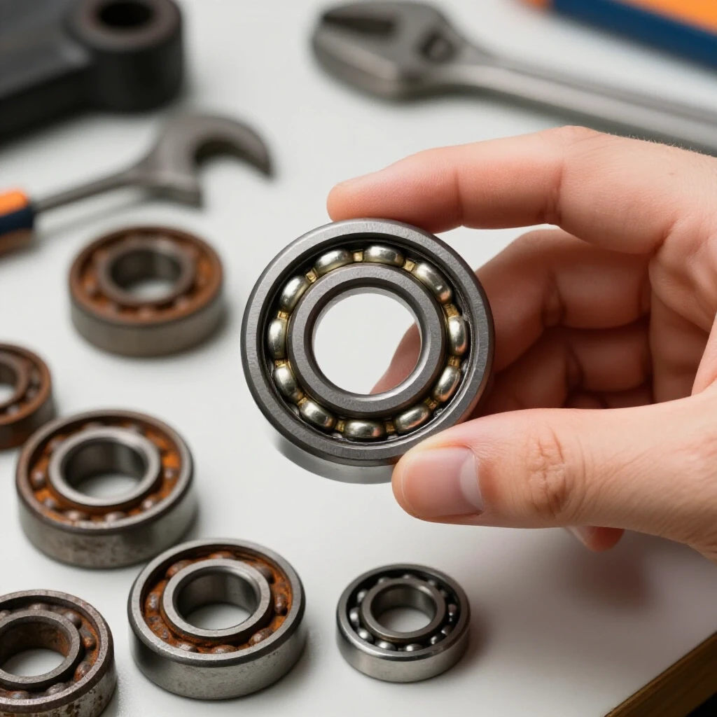
| High-pitched whining | Bearing failure or dry gears | Listen for frequency change under load | Regrease gearbox or replace tool |
| Wavy surface finish | Spindle backlash | Dial indicator run-out test | Replace spindle bearings |
| Tool “walking” or skipping | Excessive RPM for the grit | Check RPM rating vs. tool speed | Match disc to tool’s rated RPM |
Troubleshooting Surface Contaminants to Prevent Weld Porosity
Weld porosity is a defect characterized by small holes or “pits” in the weld bead, caused by gas being trapped in the molten metal as it cools. These gases usually come from the thermal breakdown of oils, moisture, or mill scale left on the joint during the preparation phase.
If you are seeing bubbles in your puddle, your cleaning process is failing. I once worked on a project where we couldn’t get a clean root pass no matter what we did. We checked the shielding gas, the flow meter, and the wire. It turned out the “clean” rags we were using to wipe down the joints had been washed with a fabric softener that left a waxy residue. This residue turned into gas the moment the arc hit it.
To speed up cleaning without sacrificing quality, I follow a strict mechanical-to-chemical sequence. First, use a dedicated stainless steel wire brush or a flap disc to remove the “mill scale”—that dark, flaky outer layer on hot-rolled steel. Mill scale is an iron oxide that melts at a much higher temperature than the base steel, which can lead to lack of fusion. Once the scale is gone, a quick wipe with acetone or 90% isopropyl alcohol is necessary. Avoid chlorinated solvents like brake cleaner, as they can produce toxic phosgene gas when heated by a welding arc.
The “White Cloth” Diagnostic Test
- Grind the joint to a bright metal finish.
- Take a clean, white lint-free cloth dampened with acetone.
- Wipe the joint in one direction.
- If the cloth shows any grey or black streaks, the joint is still contaminated.
- Repeat until the cloth comes away white. This adds two minutes now but saves an hour of grinding out a failed weld later.
Mechanical Alignment and the Geometry of High-Speed Fit-Up
Fit-up refers to the spatial relationship between the two pieces of metal being joined, including the “root gap” (the space between them) and the “bevel angle” (the slope ground into the edge). Proper geometry ensures that the weld penetrates deeply and requires less filler metal, which speeds up the entire fabrication process.
If your fit-up is inconsistent, your welding speed will vary as you try to bridge large gaps or melt through thick, un-beveled sections. I aim for a 30-degree to 37.5-degree bevel on plates thicker than 3/16 of an inch. This creates a 60-to-75-degree “included angle” when the two plates are put together, which is the sweet spot for most DIY welding processes like MIG or Stick.
To ensure alignment stays true, I use “dogs and wedges” or simple bridge clamps. If you are dealing with material warping during the prep or tacking stage, it is often because of “residual stress” in the metal from the mill. When you grind one side of a plate, you remove a small amount of tension, which can cause the plate to bow. To diagnose this, I use a straightedge across the joint. If I see a gap of more than 1/32 of an inch over a foot of length, I know I need to use a clamping sequence that counteracts that bow before I start tacking.
Vibration Analysis and Tool Maintenance for Consistent Results
Maintaining your prep tools is a diagnostic necessity, not just a chore. A tool that is running at peak efficiency removes more material with less physical effort, which is the key to reducing the time spent on joint preparation.
I treat my grinders like precision instruments. Every month, I blow out the motor housings with compressed air to remove metallic dust. This dust is conductive and can cause “tracking” or “arcing” across the motor’s commutator, leading to power loss and eventual motor failure. If you notice your grinder slowing down under a light load, you likely have worn carbon brushes or a build-up of debris in the cooling vents.
Another factor is the “feed-per-tooth” logic applied to abrasives. While a flap disc doesn’t have teeth like a saw blade, it does have a specific amount of “bite” it can take before the grit becomes “loaded” or clogged with melted metal. If you push too hard, the friction generates heat rather than removing chips. This is why I prefer a 40-grit ceramic flap disc for heavy removal; it stays cooler and cuts faster than standard aluminum oxide.
Essential Diagnostic Tools for Prep Efficiency
- Digital Calipers: For measuring root face thickness (aim for 1/16 inch for consistency).
- Infrared Thermometer: To monitor pre-heat temperatures and ensure you aren’t overheating the metal during grinding (which can cause localized hardening).
- Smartphone Vibration App: Use a simple seismograph app to check the vibration levels of your bench and tools; it’s a great way to find “dead spots” where you should add weight to your table.
- Feeler Gauges: To check for consistent root gaps across long seams.
Case Study: The Mystery of the Shifting Bevel
I once consulted for a shop that was struggling with inconsistent bevel depths on a large batch of structural tubing. They were using a manual beveling machine, but the edges were coming out “stepped.” The operator thought it was a bad batch of steel.
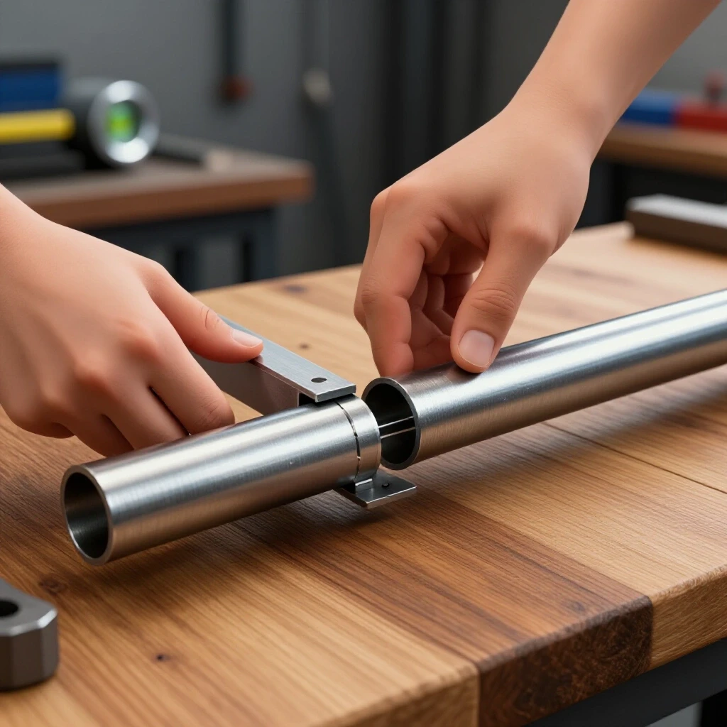
I started by checking the machine’s mounting. I found that the clamping mechanism had 0.010 inches of play due to a stripped thread in the adjustment bolt. As the tool moved along the tube, the vibration caused the clamp to vibrate loose just enough to let the tool depth shift. By replacing the bolt and adding a locking nut, we eliminated the play. The prep time per tube dropped from 8 minutes to 3 minutes because they no longer had to go back and “clean up” the uneven steps. This highlights the importance of checking your mechanical baselines before blaming the material or the process.
Actionable Tracking Framework for Shop Prep
To truly master the speed of your workflow, you need to track your variables. I recommend keeping a small logbook near your prep station. When you find a combination of tool, abrasive, and technique that works perfectly, write it down.
- Material Type: (e.g., A36 Mild Steel)
- Tool Used: (e.g., 5-inch Angle Grinder, 10 Amp)
- Abrasive: (e.g., 36 Grit Zirconia Disc)
- Time per Foot: (e.g., 4 minutes)
- Weld Quality: (e.g., Zero porosity, full penetration)
By looking back at these metrics, you can quickly diagnose why a current job is taking longer. If your usual 4-minute-per-foot prep is suddenly taking 7 minutes, you know to check for a dull disc, a dropping voltage in your shop’s power line, or a change in the material’s mill scale thickness.
Conclusion: The Path to Faster Fabrication
Speeding up the preparation phase of metalwork is not about moving your arms faster; it is about removing the mechanical and metallurgical obstacles that slow you down. By diagnosing tool chatter, eliminating the sources of porosity, and ensuring precise mechanical alignment, you create an environment where the welding itself becomes the easiest part of the job.
Start by auditing your tools for spindle play and vibration. Move on to refining your cleaning sequence with the white cloth test. Finally, use jigs and consistent bevel angles to ensure your fit-up is perfect every time. These systematic steps turn a frustrating, high-effort task into a streamlined, predictable process that saves your hands, your tools, and your schedule.
Frequently Asked Questions
Why does my grinder vibrate more on some days than others?
Vibration changes are often linked to the “loading” of the abrasive disc or the temperature of the tool’s grease. If the disc is clogged with soft metal like aluminum or heavy mill scale, it becomes unbalanced. Additionally, if your shop is very cold, the grease in the gearbox may be too thick, causing a temporary imbalance until the tool warms up.
How can I tell if my bevel angle is correct without a protractor?
A quick “shop trick” is to use a square. If you are aiming for a 45-degree bevel, the width of the bevel should be equal to the depth of the cut. For a 30-degree bevel, the width of the ground face should be approximately 1.7 times the depth of the cut. However, I always recommend buying a cheap “bridge cam” gauge for precise measurements.
Can I use a wire wheel instead of a grinding disc for prep?
A wire wheel is excellent for removing loose rust or paint, but it is poor at removing mill scale. In fact, a wire wheel can sometimes “burnish” or polish the mill scale, making it even harder to weld through. For a true structural prep, always start with a grinding disc or flap disc to reach bright, bare metal.
What is the fastest way to remove heavy mill scale?
The most efficient manual method is using a “cubitron” or ceramic-grained grinding disc. These grains are engineered to break away and stay sharp, whereas standard aluminum oxide grains round over and get hot. A 36-grit ceramic disc will usually cut through heavy scale twice as fast as a standard disc.
Why do I keep getting porosity even after grinding the metal?
Check your cleaning solvent and your environment. If you are grinding near a station where someone is using silicone spray or WD-40, the airborne particles can land on your clean joint. Also, ensure you are grinding back at least one inch from the edge of the joint on both the top and bottom surfaces, as contaminants can “wick” into the weld from the underside.
How much of a root gap should I leave for a DIY project?
For most 1/8 inch to 1/4 inch thick materials, a root gap of about 1/16 of an inch (the thickness of a standard MIG welding wire or a thin zip-cut blade) is ideal. This allows the arc to reach the bottom of the joint for full penetration without the risk of the pieces falling through.
Does the direction of my grinding marks matter?
Yes. Whenever possible, grind parallel to the direction of the joint. Transverse grinding marks (perpendicular to the weld) can create tiny “valleys” that trap slag or shielding gas, leading to small inclusions or porosity. Parallel marks allow the molten metal to flow more smoothly into the root.
How do I stop my workpieces from “walking” apart during tacking?
This is caused by the cooling of the tack weld, which pulls the metal toward the weld. To counter this, use a “wedge” at the far end of the joint to hold the gap open slightly wider than you want it. As you tack toward the wedge, the shrinking metal will pull the gap into the perfect dimension.
Is it safe to use a flap disc on its side for beveling?
No. Flap discs are designed to be used at an angle (usually 15 to 25 degrees). Using them flat or on the very edge can cause the flaps to tear off at high speed, which is a major safety hazard. For steep bevels, use a dedicated hard grinding stone or a specialized beveling tool.
How often should I replace the brushes in my angle grinder?
Most manufacturers recommend checking them every 50 to 100 hours of use. If the brushes are worn down to less than 1/4 inch, replace them. Worn brushes cause arcing, which reduces the tool’s torque and makes your prep work take much longer than necessary.
(This article was written by one of our staff writers, Paul Whitaker. Visit our Meet the Team page to learn more about the author and their expertise.)