How to Track and Analyze Workshop Production Times (Tutorial)
I spent the first decade of my fabrication career working in a shop that felt more like an obstacle course than a production facility. Every time I needed to move a 4×8 sheet of 11-gauge steel to the gantry, I had to shift a welding cart, sidestep a pile of offcuts, and pray the forklift had enough swing room. It was exhausting, and more importantly, it was slow. When I finally transitioned from a hobbyist mindset to a micro-manufacturing operation, I realized that my biggest enemy wasn’t my skill level—it was the invisible friction of my own workshop layout.

Scaling a fabrication business is often a game of inches and seconds. You start noticing that the time it takes to walk from the saw to the welding bench adds up to hours over a month. You realize your single-phase power is holding back the industrial-grade equipment you need to stay competitive. In this guide, I will walk you through the systematic process of auditing your space, upgrading your infrastructure, and logging the actual minutes spent on fabrication tasks to transform your shop into a high-output environment.
Mapping Material-Flow Loops to Minimize Travel Distance
Material-flow mapping is the process of documenting the physical path a piece of raw stock takes from the moment it enters the shop until it leaves as a finished product. By visualizing these paths, you can identify “spaghetti” patterns where tools and materials cross paths unnecessarily, causing safety hazards and wasted movement.
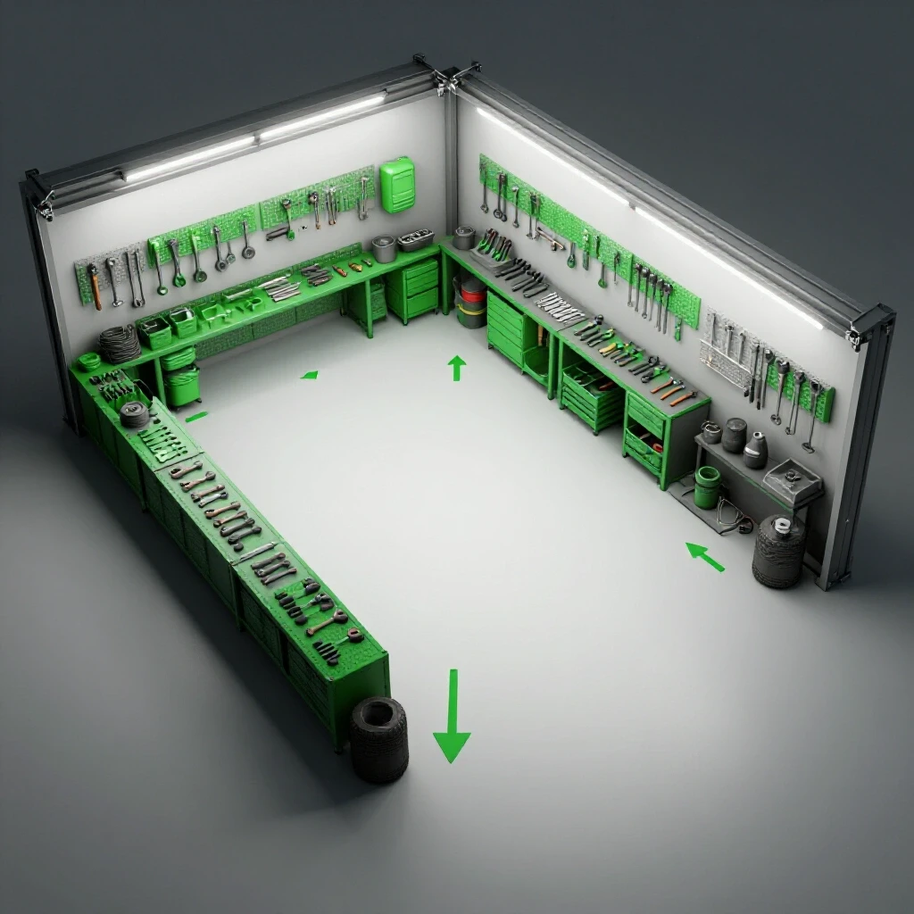
In my shop, I used a simple floor plan and a red marker to trace the path of a standard bracket project. I found that the steel traveled nearly 200 feet between the rack, the saw, the CNC plasma table, and the welding station. By rearranging the machines into a more linear advanced workshop layout, I cut that travel distance by 60 percent. The goal is to move the material in a straight line or a tight U-shape, ensuring the heaviest stock spends the least amount of time in transit.
Why Back-and-Forth Foot Traffic Kills Shop Throughput
This refers to the “hidden” time spent walking between tools or searching for consumables, which can consume up to 30% of a work day. Reducing these movements involves placing secondary tools, like grinders or clamps, within an arm’s reach of the primary work zones to maintain a steady production rhythm.
- Establish “Work Cells”: Group the saw and material rack together to handle the dirty, heavy phase of production in one zone.
- Keep Tooling Redundant: If you find yourself walking across the shop for a 4.5-inch grinder, buy a second one for the other side of the room.
- Clear the Aisles: Maintain a minimum 3-foot access zone around every major machine to ensure you aren’t squeezing past obstacles while carrying sharp metal.
| Layout Type | Material Travel Distance | Efficiency Rating | Best Use Case |
|---|---|---|---|
| Random/Hobby | High (150+ ft) | Low | Low-volume custom work |
| U-Shaped | Medium (50-80 ft) | High | Small shops with one door |
| Linear/Flow | Low (20-40 ft) | Highest | High-volume production lines |
Measuring Floor Capacities and Machine Zoning
Floor capacity analysis involves calculating the weight-bearing limits of your concrete slab to ensure it can support heavy machinery like CNC plasma tables or ironworkers without cracking. Zoning is the practice of dedicating specific areas to “hot” work, “dirty” work, and “clean” work to prevent cross-contamination and improve safety.
When I installed my first heavy CNC plasma table, I didn’t just look at the footprint; I looked at the weight of the water table when full. A standard 4-inch residential slab might hold 2,500 to 3,000 PSI, but a concentrated load on four small legs can exceed that quickly. I recommend verifying your slab thickness—usually 4 to 6 inches for light industrial—and using steel spreader plates under machine feet if you are pushing the limits of your floor load ratings.
Creating High-Efficiency Work Zones
A work zone is a dedicated area designed for a specific stage of the fabrication process, equipped with all necessary power, air, and tooling. Effective zoning prevents grinding dust from entering your CNC electronics and keeps welding sparks away from your fuel and gas storage areas.
- Hot Zone: Welding and cutting areas with fire-resistant shielding.
- Dirty Zone: Grinding and sanding stations located near the main exhaust or dust collection.
- Precision Zone: CNC gantry and computer stations, ideally isolated from heavy vibration and metallic dust.
Analyzing Power Limits and Building Balanced 3-Phase Systems
Electrical load analysis is the systematic review of your shop’s total amperage draw to ensure your service can handle the simultaneous operation of CNC systems, compressors, and welders. For many home-based shops, this involves converting standard single-phase residential power into 3-phase power to run industrial-grade motors.
Most of the high-end fabrication equipment you’ll want as you scale—like heavy-duty cold saws or large air compressors—runs more efficiently on 3-phase power. In my experience, a rotary phase converter is the most reliable way to bridge this gap. It uses a 3-phase motor (an idler) to generate the third leg of power, providing a cleaner signal than most cheap static converters. However, you must monitor your phase balance; if the voltage between legs varies by more than 5-10%, you risk overheating your expensive CNC motors.
Comparing Power Conversion Options for Scaling Shops
Power conversion tools allow a shop owner to run industrial machinery on residential grids, though each method has trade-offs in terms of cost and power quality. Choosing the right one depends on whether you are running a single machine or an entire suite of 3-phase equipment.
- Rotary Phase Converters: Best for running multiple machines simultaneously. They provide “true” 3-phase power but are loud and consume electricity even when the machines are idling.
- Variable Frequency Drives (VFDs): Excellent for single machines where you want speed control. They are efficient but can be complex to wire for CNC applications.
- Digital Phase Converters: The gold standard for clean power. They are silent and highly efficient but come with a capital cost that can be three times higher than a rotary unit.
| Converter Type | Power Quality | Cost | Best Application |
|---|---|---|---|
| Static | Poor | Low | Small drills/lathes (rarely used) |
| Rotary | Good | Medium | General shop-wide 3-phase |
| Digital | Excellent | High | Sensitive CNC electronics |
Designing High-Volume Clean Air Filtration and Fume Management
Air quality management in a fabrication shop involves calculating the required Cubic Feet per Minute (CFM) of airflow to remove hazardous fumes and dust from the breathing zone. This requires a combination of source capture (like a fume extractor) and ambient air scrubbing to meet safety standards.
When I started running long programs on my CNC plasma table, the shop would fill with a fine brown haze in minutes. I learned the hard way that a standard shop vac isn’t enough. You need to understand static pressure loss—the resistance air faces as it moves through ducts. Using 6-inch smooth-walled metal ducting instead of 4-inch flexible hose can double your actual CFM at the tool. For a professional-level CNC plasma table setup, I aim for at least 1,000 to 1,500 CFM at the source to keep the air clear.
Calculating Duct Velocity and Static Pressure
Duct velocity is the speed at which air moves through your pipes, measured in feet per minute (FPM). You need enough velocity (usually around 3,500 to 4,000 FPM for metal dust) to keep particles suspended so they don’t settle and clog your pipes.
- Use long-radius elbows instead of T-junctions to reduce air turbulence.
- Install a multi-stage cyclone separator to catch heavy sparks and chips before they reach your fine filters.
- Check filter pressure gauges weekly; a clogged filter can drop your CFM by 50% without you noticing the change in sound.
Integrating CNC Tool Workflows and Gantry Calibration
CNC integration is the process of bringing automated cutting or milling into your manual workflow, which requires precise machine leveling and software synchronization. This transition involves moving from hand-held tools to a CAD/CAM environment where the machine executes digital designs with high repeatability.
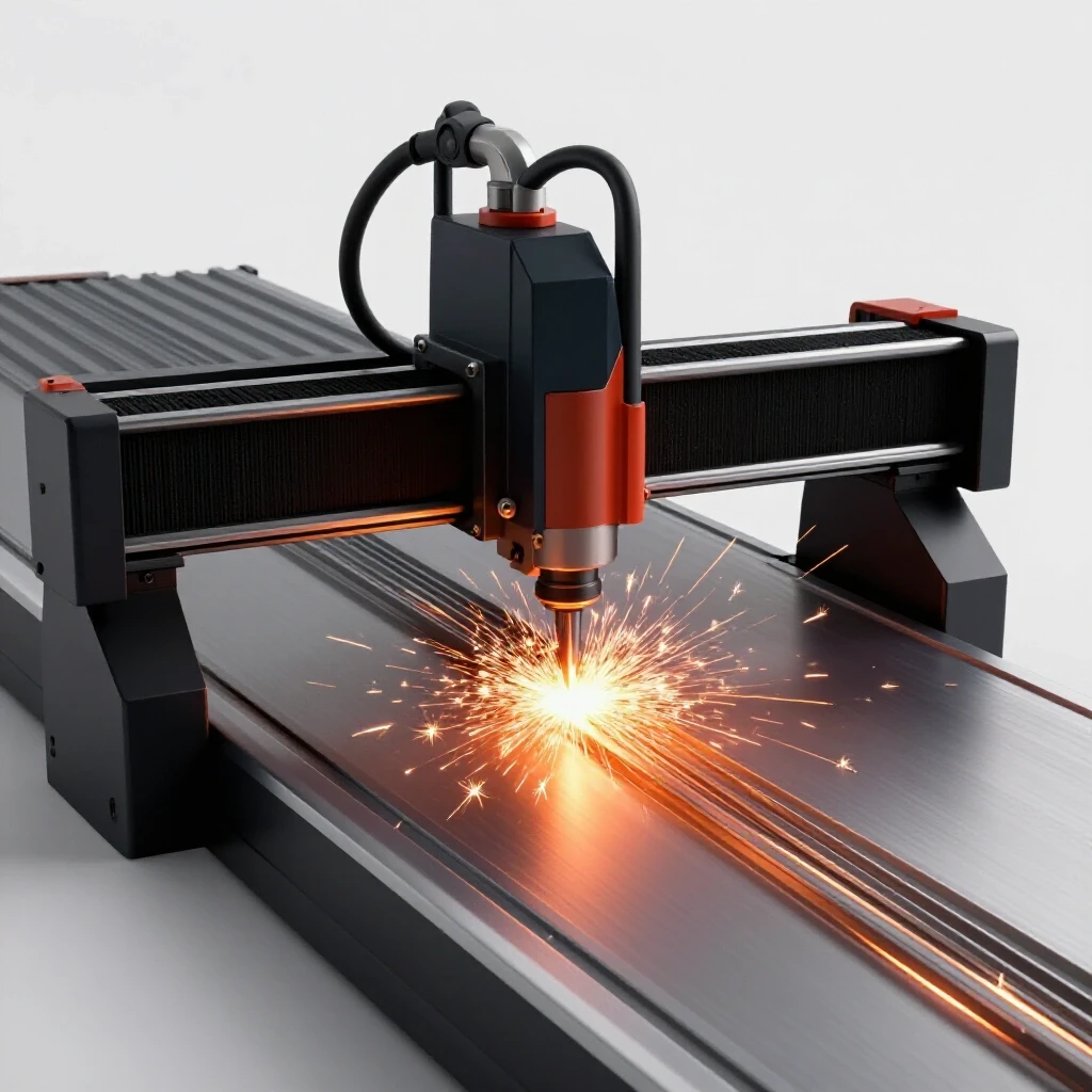
The biggest mistake I see with a new CNC plasma table setup is rushing the leveling process. If your gantry is off by even a fraction of an inch over a 4-foot span, you’ll fight torch height control issues and premature consumable wear forever. I spend at least a full day using a precision machinist’s level and squaring the gantry to the frame using the 3-4-5 triangle method. This ensures that when you log your cutting durations later, the data isn’t skewed by machine errors or failed starts.
Essential Steps for Commissioning a CNC Gantry
Commissioning is the final stage of setup where you verify that the machine moves and cuts exactly as the software intends. This involves “dry runs” without the torch firing to check for mechanical interference or cable snagging.
- Mechanical Squaring: Ensure the X and Y axes are perfectly perpendicular to avoid “parallelogram” cuts.
- Motor Tuning: Adjust your acceleration and velocity settings in the controller software to prevent the gantry from shaking at high speeds.
- Torch Height Control (THC) Calibration: Verify that the torch maintains a consistent 0.060-inch gap from the metal surface during the cut.
- Software Post-Processor Check: Ensure your CAD/CAM software is outputting the specific G-code that your machine controller understands.
Logging and Refining Operation Durations for Throughput Analysis
Operation logging is the practice of recording the actual time it takes to complete specific fabrication steps, such as sawing stock or welding a seam. By analyzing these logs, a shop owner can identify bottlenecks where a process is taking longer than expected, allowing for targeted improvements.
To truly understand your shop’s performance, you need to stop guessing how long a job takes. I started keeping a simple clipboard at each station—saw, CNC, and welding bench. I would log the start and stop times for every batch of parts. Interestingly, I found that “grinding and prep” often took twice as long as the actual welding. This data-driven approach allowed me to invest in a better edge-prepping tool, which immediately increased my daily output by 15 percent.
Tracking Key Fabrication Metrics
Fabrication metrics are the specific data points you track to measure the health of your production flow. Focusing on these numbers helps you move away from “feeling” busy to actually being productive.
- Saw Time: The duration from the first cut to the last for a specific project.
- Arc-On Time: The actual minutes spent welding, which is often much lower than people realize.
- Fit-Up Time: The time spent clamping and tacking parts before the final weld.
- Clean-Up/Grinding: The time spent removing dross or smoothing welds.
| Operation | Estimated Time | Actual Logged Time | Variance | Solution |
|---|---|---|---|---|
| Stock Sawing | 20 mins | 45 mins | +25 mins | Move rack closer to saw |
| CNC Cutting | 15 mins | 20 mins | +5 mins | Optimize lead-ins |
| MIG Welding | 30 mins | 35 mins | +5 mins | Improve jigging |
| Final Grinding | 10 mins | 40 mins | +30 mins | Use cleaner CNC settings |
Practical Frameworks for Workshop Optimization
An optimization framework is a structured plan used to evaluate and improve shop performance over time. It involves setting benchmarks, measuring current output, and making incremental changes to machinery or layout to reach those goals.
When you are scaling a fabrication shop, it’s easy to get overwhelmed by the “to-do” list. I use a “bottleneck-first” strategy. If the saw is the slowest part of the day, I don’t buy a new welder; I fix the saw process. This might mean adding a digital stop system or a roller table to handle long sticks of tubing. By focusing on the one thing that is holding everything else up, you get the highest return on your investment of time and money.
A Weekly Audit for Shop Efficiency
A weekly audit is a short, dedicated time to review your production logs and look for patterns of wasted time. This prevents small inefficiencies from becoming permanent habits in your workflow.
- Review Logs: Look for any task that consistently took 20% longer than planned.
- Inspect Consumables: Check CNC nozzles and saw blades; dull tools are the primary cause of slow production times.
- Walk the Path: Physically walk your material flow path and look for new “clutter” that has appeared during the week.
Actionable Benchmarks for the Evolving Shop
Benchmarks are the standard metrics used to compare your shop’s performance against industry norms or your own past performance. They provide a clear target for what a “good” day of production looks like in a semi-professional space.
For a shop transitioning to automation, I look for specific indicators of success. For example, your CNC plasma table should have an “uptime” of at least 70% during a cutting shift, meaning the torch is actually moving and cutting for most of the hour. If it’s only at 30%, you have a software or material handling bottleneck that needs to be addressed. Similarly, in a well-laid-out shop, your “handling time” (moving metal around) should never exceed your “processing time” (cutting or welding metal).
- Machine Spacing: Minimum 3 feet of clearance on all sides of stationary tools.
- Air Quality: Ambient air should be clear of visible haze within 5 minutes of a heavy cutting session ending.
- Power Balance: 3-phase legs should stay within 5% of each other under load to protect CNC electronics.
- Material Handling: No piece of stock should be moved more than three times before it is a finished part.
The journey from a hobby setup to a high-output fabrication space is rarely a single “big bang” upgrade. It is a series of calculated moves—straightening a material path here, balancing a 3-phase load there, and religiously logging the minutes spent at the grinder. As you integrate CNC technology and lean principles, remember that the goal isn’t just to work faster, but to work with less friction. By focusing on the data and the physical flow of your shop, you can build a facility that supports your skill rather than standing in its way.
FAQ: Common Questions on Workshop Scaling and Efficiency
What is the best way to track my time without it being a distraction? I recommend using a simple analog clock and a dedicated logbook at each major workstation. Avoid using complex apps on your phone, as they often lead to distractions. The goal is to spend five seconds logging a start time and five seconds logging a stop time.
How do I know if I need a rotary phase converter or a VFD? If you have multiple 3-phase machines or a CNC system with sensitive electronics, a rotary phase converter is usually the better choice for shop-wide power. If you only have one manual lathe or mill and want to control its speed, a VFD is more cost-effective.
How much CFM do I really need for a CNC plasma table? For a 4×4 or 4×8 table, you should aim for a minimum of 1,000 CFM of actual airflow at the source. If you are using a water table, you may need less for fumes, but you will still need a way to manage the fine dust that escapes the water’s surface.
Why is my CNC gantry losing steps during long programs? This is often caused by mechanical binding or electrical interference. Check that your gantry is perfectly square and that your signal cables are shielded and kept away from high-voltage power lines like your plasma torch lead.
Can I run a CNC plasma table on a standard 4-inch concrete floor? Yes, most tables are fine on a 4-inch slab, but you should use steel pads (at least 6×6 inches) under the leveling feet to distribute the weight. This prevents the concentrated load from causing “spalling” or cracking over time.
What is the “spaghetti map” in workshop layout? A spaghetti map is a diagram where you draw a line for every movement a person or material makes during a job. If the resulting drawing looks like a plate of tangled spaghetti, your layout is inefficient and needs to be reorganized into a more linear flow.
How often should I balance my 3-phase converter? You should check the voltage balance with a multimeter once a month or whenever you add a new machine to the circuit. Unbalanced legs can lead to motor overheating and premature failure of CNC drivers.
What is the most common bottleneck in a scaling metal shop? In my experience, it is almost always material handling and prep. People spend a lot of money on a fast CNC table but still use a slow, manual bandsaw or have their steel stored in a way that requires moving five other pieces to get to the one they need.
How do I calculate static pressure loss in my dust collection? Static pressure loss is calculated based on the length of the pipe, the number of bends, and the diameter of the duct. There are several online calculators specifically for shop owners, but a good rule of thumb is that every 90-degree elbow adds the equivalent of 5 to 10 feet of straight pipe resistance.
Is it worth it to log time for every single project? You don’t need to do it forever. I suggest logging every project for one month. This provides enough data to see the patterns. After that, you only need to log time when you introduce a new tool or change your layout to see if the improvement worked.
(This article was written by one of our staff writers, Edward Sinclair. Visit our Meet the Team page to learn more about the author and their expertise.)