How to Verify Part Alignment and Squaring in the Shop (Tips)
In my fourteen years of metal fabrication, I have learned that a project rarely fails at the finish line. Failure usually starts much earlier, often during the first few minutes of layout. I once worked on a heavy-duty engine stand for a local shop. On the surface, the welds looked deep and clean, but when we mounted the block, the entire structure leaned three degrees to the left. That tiny error created an eccentric load that put massive shear stress on the mounting bolts. It was a humbling reminder that if your base is not perfectly true, the rest of the build is just a countdown to a structural headache.
For those of us working in a shop, precision is not about being a perfectionist. It is about safety and predictable performance. When a frame is out of square, the load paths change. Instead of the weight traveling straight down a column, it begins to push sideways. This can lead to brittle fractures or structural buckling under loads that the metal should easily handle. Mastering the art of checking for perpendicularity and parallelism is the only way to ensure your project performs exactly how you designed it on paper.
The Physics of Perpendicularity in Structural Frames
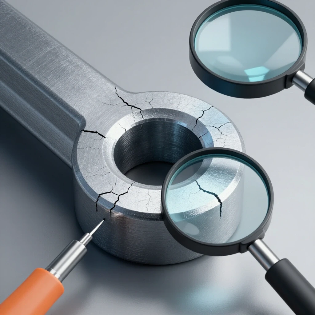
Checking for perpendicularity ensures that two intersecting members meet at exactly 90 degrees. This alignment is critical because it allows vertical loads to transfer directly into the ground or base without creating side-loading forces. When parts are not square, the internal stress on joints increases significantly, often leading to premature metal fatigue or cracking.
In the world of structural metal load capacity, geometry is your best friend or your worst enemy. If a vertical support is tilted, the force of gravity creates a “moment arm.” This means the weight is trying to bend the metal rather than just compress it. Most structural steel, like A36, has a high yield strength of around 36,000 PSI, but it is much weaker when you apply force in directions it wasn’t meant to go.
By ensuring your parts are square, you maintain the intended load path. I always tell intermediate fabricators to think about the heat affected zone weakness. If your joint is poorly aligned, the stress will naturally find the weakest point—usually the area right next to the weld where the metal’s grain structure was altered by heat. Keeping things square reduces the chance of that stress becoming a failure point.
| Connection Type | Alignment Goal | Primary Stress Risk | Safety Factor Target |
|---|---|---|---|
| T-Joint | 90° Perpendicular | Shear at the root | 3:1 |
| Corner Joint | 90° Perpendicular | Tensile pulling | 4:1 |
| Butt Joint | 180° Parallel | Bending moment | 2:1 |
| Lap Joint | Flat Parallel | Peeling stress | 3:1 |
Essential Manual Tools for Dimensional Accuracy
Manual verification requires a set of trusted tools that provide consistent, repeatable results without the need for digital screens. Machinist squares, combination squares, and precision straightedges are the backbone of a reliable inspection process. These tools allow you to see the “light gap” between the tool and the workpiece, which is a primary indicator of misalignment.
I have spent a decade relying on a high-quality 12-inch machinist square. Unlike the cheap versions found in big-box stores, a true machinist square is ground to a tolerance of within 0.0005 inches. When I place it against a tube steel frame, I am looking for any sliver of light passing through the contact point. If I see light at the top but not the bottom, I know the part is leaning.
Another vital tool is the dial indicator. While often associated with machining, it is incredibly useful for checking if a long rail is parallel to your work surface. By sliding the indicator along the length of a part, you can see exactly where it begins to drift. This is much more accurate than a tape measure, which can have a “hook” error of up to 1/32 of an inch.
- Machinist Square: Used for checking internal and external 90-degree angles.
- Combination Square: Best for quick layout and checking 45-degree miters.
- Straightedge: A hardened steel bar used to verify that a surface is flat across its entire length.
- Dial Indicator: Measures small deviations in a surface, usually in increments of 0.001 inches.
- Surface Plate: A heavy, flat slab (usually granite) that serves as the “ground truth” for all measurements.
Establishing a Reference Datum for Reliable Measurements
A reference datum is a starting point or a “zero” surface that you know is perfectly flat and true. Without a reliable datum, every other measurement you take is just a guess based on another guess. In a professional shop, this is usually a granite surface plate or a precision-ground welding table that has been leveled to the floor.
When I start a project, I treat my workbench as the foundation of my workshop safety checklist. If the table is warped, the project will be warped. If you don’t have a professional surface plate, you can use a thick piece of cold-rolled steel plate, provided you have verified it with a straightedge.
Once you have your datum, every part you measure should be referenced back to it. For example, if you are building a four-sided frame, you don’t just check the corners. You check how each side sits against the flat table. If one corner lifts off the table, you have a “twist,” also known as a wind. This is often caused by internal stresses in the metal or uneven clamping.
- Clean the datum surface of all grit, weld spatter, and oil.
- Place the largest component of your project on the surface.
- Use a feeler gauge to see if there are gaps between the part and the table.
- If a gap exists, the part is either bowed or the table is not flat.
- Mark the “high spots” with a paint pen so you know where the error begins.
The Repeatable Measurement Sequence for Assembly
A repeatable measurement sequence is a step-by-step process used to verify dimensions at every stage of the build. Instead of checking only at the end, you verify the alignment before tacking, after tacking, and halfway through the final welding process. This prevents small errors from compounding into a major structural failure that is impossible to fix.
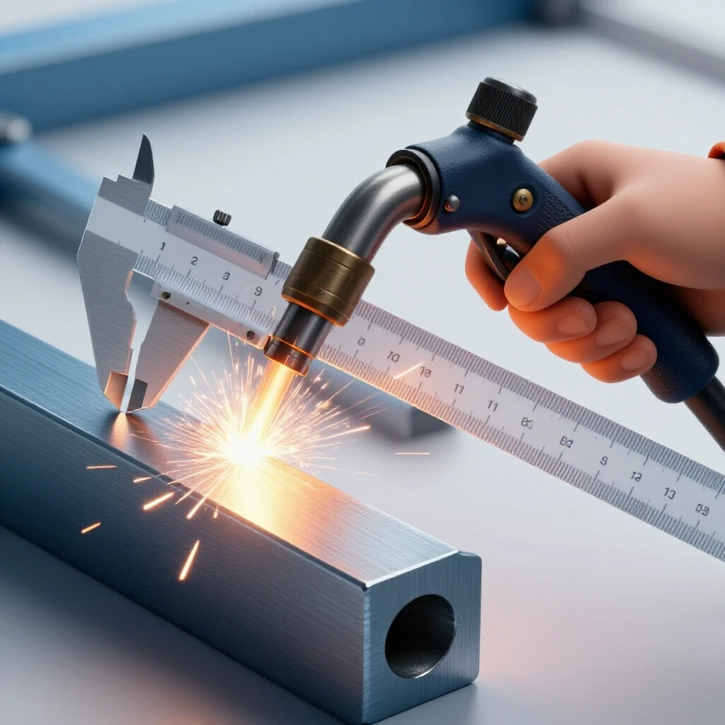
I follow a “Check Twice, Weld Once” rule, but it is more like “Check Four Times.” First, I dry-fit the parts and check for square. Then, I apply small tack welds. Welding causes metal to expand and contract, which can pull a perfectly square joint out of alignment. This is where most garage fabrication safety issues start—ignoring the movement of the metal during the tacking phase.
After the tacks are cooled, I re-verify the angles. If the part moved, I can easily break a tack and reset it. Interestingly, if you wait until the joint is fully welded, you would have to cut the entire piece out, wasting material and time. Using a standardized sequence ensures that you aren’t guessing whether the heat of the torch moved your frame.
- Initial Fit-Up: Check for gaps and squareness before any heat is applied.
- Tack Verification: Check again after the first two tacks are placed at opposite corners.
- Mid-Point Check: Stop halfway through the weld to ensure the heat hasn’t pulled the part.
- Final Inspection: A comprehensive check of all dimensions once the part has returned to room temperature.
Understanding Tolerance and Precision Standards
Tolerance is the allowable amount of error in a measurement, while precision is the ability to repeat that measurement consistently. In structural fabrication, tolerances are often defined by the American Welding Society (AWS). Knowing your required tolerance helps you decide which tools to use and how much time to spend on alignment.
For most structural frames, a common tolerance is 1/16 of an inch over a 10-foot span. If you are building something more delicate, like a mounting bracket for a motor, you might need to stay within 0.010 inches. I often see hobbyists getting frustrated because they are trying to hold a “zero” tolerance on a rough-sawn piece of angle iron.
It is important to match your measurement tool to your tolerance. You wouldn’t use a tape measure to check a bearing fit, and you wouldn’t use a micrometer to measure a fence post. In my experience, understanding these limits prevents “analysis paralysis” and keeps the project moving safely.
| Project Type | Common Tolerance | Recommended Tool |
|---|---|---|
| Heavy Structural Frame | +/- 1/16″ | Steel Tape & Framing Square |
| Machine Base | +/- 0.015″ | Machinist Square & Straightedge |
| Precision Jig/Fixture | +/- 0.005″ | Dial Indicator & Surface Plate |
| Sheet Metal Box | +/- 1/32″ | Combination Square |
Using the 3-4-5 Rule for Large Scale Squaring
The 3-4-5 rule is a practical application of the Pythagorean theorem (A² + B² = C²) used to verify 90-degree angles on large structures where a standard square is too small. By measuring three units on one side and four units on the adjacent side, the diagonal distance between those points must be exactly five units if the corner is square.
This technique is a lifesaver when you are building something like a trailer frame or a large floor grate. A small machinist square might tell you the corner is square, but over a ten-foot span, a tiny error at the corner can result in a two-inch deviation at the far end. I prefer to use the largest units possible for this check. Instead of 3, 4, and 5 inches, I use 3, 4, and 5 feet.
When you perform this check, use a high-quality steel tape measure. Be careful of the “hook” at the end of the tape; if it is loose or bent, it will throw off your 3-4-5 calculation. I often “burn an inch,” which means starting the measurement at the 1-inch mark instead of the hook, to ensure the most accurate reading possible.
Detecting and Correcting Twist and Wind
Twist, often called “wind” in the shop, occurs when two parallel members are not in the same plane, even if they appear straight individually. This creates a “propeller” effect in a frame, making it impossible to mount flat panels or doors. Detecting twist requires a set of “winding sticks” or a precision level used on a flat reference surface.
I once saw a heavy equipment rack that looked perfect on the welding table. But when it was bolted to the floor, one leg was a half-inch off the ground. The builder had checked for squareness at the corners but hadn’t checked if the entire frame was flat. This is a common welding defect troubleshooting scenario where the alignment seems fine in 2D but fails in 3D.
To check for wind, place two identical straightedges at opposite ends of your frame. Sight across the top of one straightedge to the other. If the two edges are not perfectly parallel, your frame has a twist. You must correct this before the final welding, often by shimmying one corner or using heavy-duty clamps to pull the metal back into plane.
- Place the frame on a known flat surface.
- Use a precision level to check the “bubble” on one end.
- Move the level to the opposite end without changing its orientation.
- If the bubble position changes, the frame is twisted.
- Use “C” clamps to pull the high corner down until the levels match.
Verifying Parallelism with Calipers and Spacers
Parallelism ensures that two lines or surfaces are the same distance apart at every point along their length. This is vital for any project involving moving parts, such as drawer slides or CNC rails. Verifying parallelism usually involves taking multiple measurements at different points or using a fixed spacer block to “feel” the consistency of the gap.
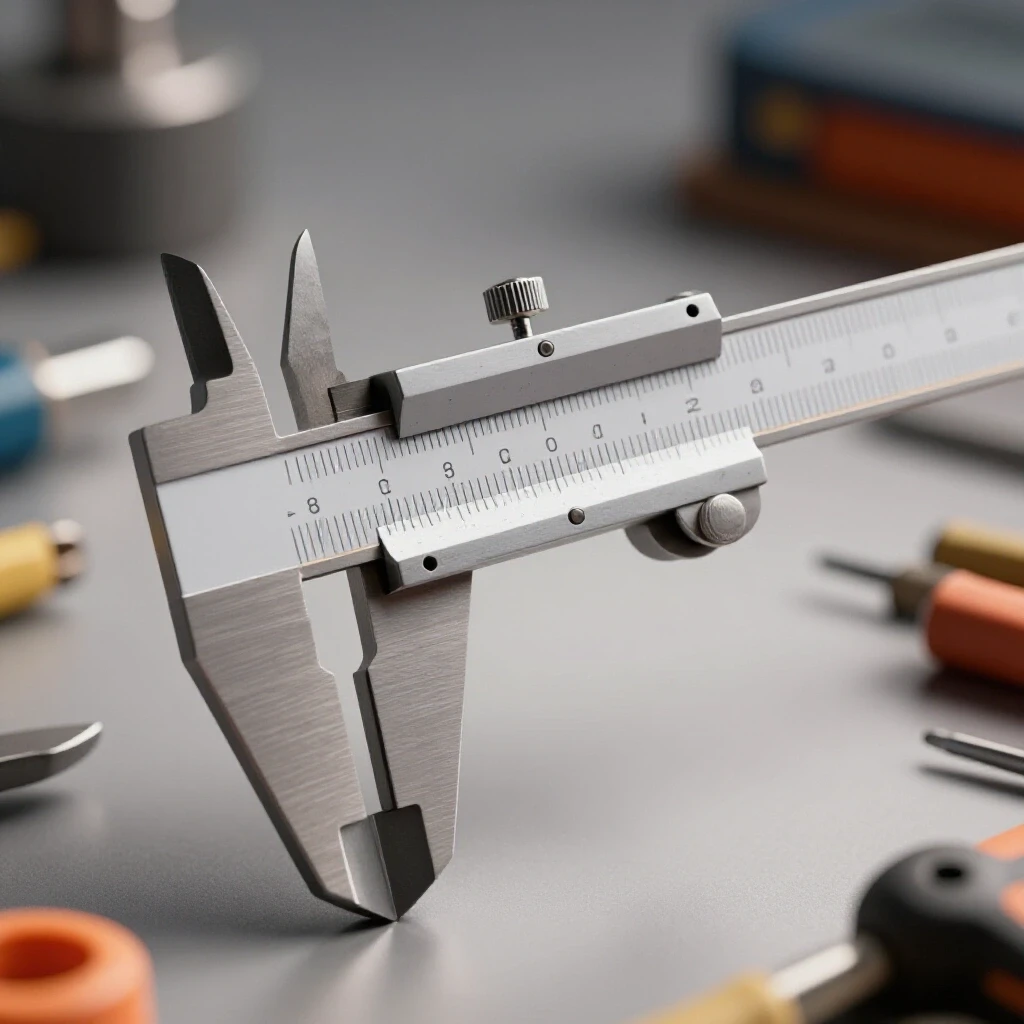
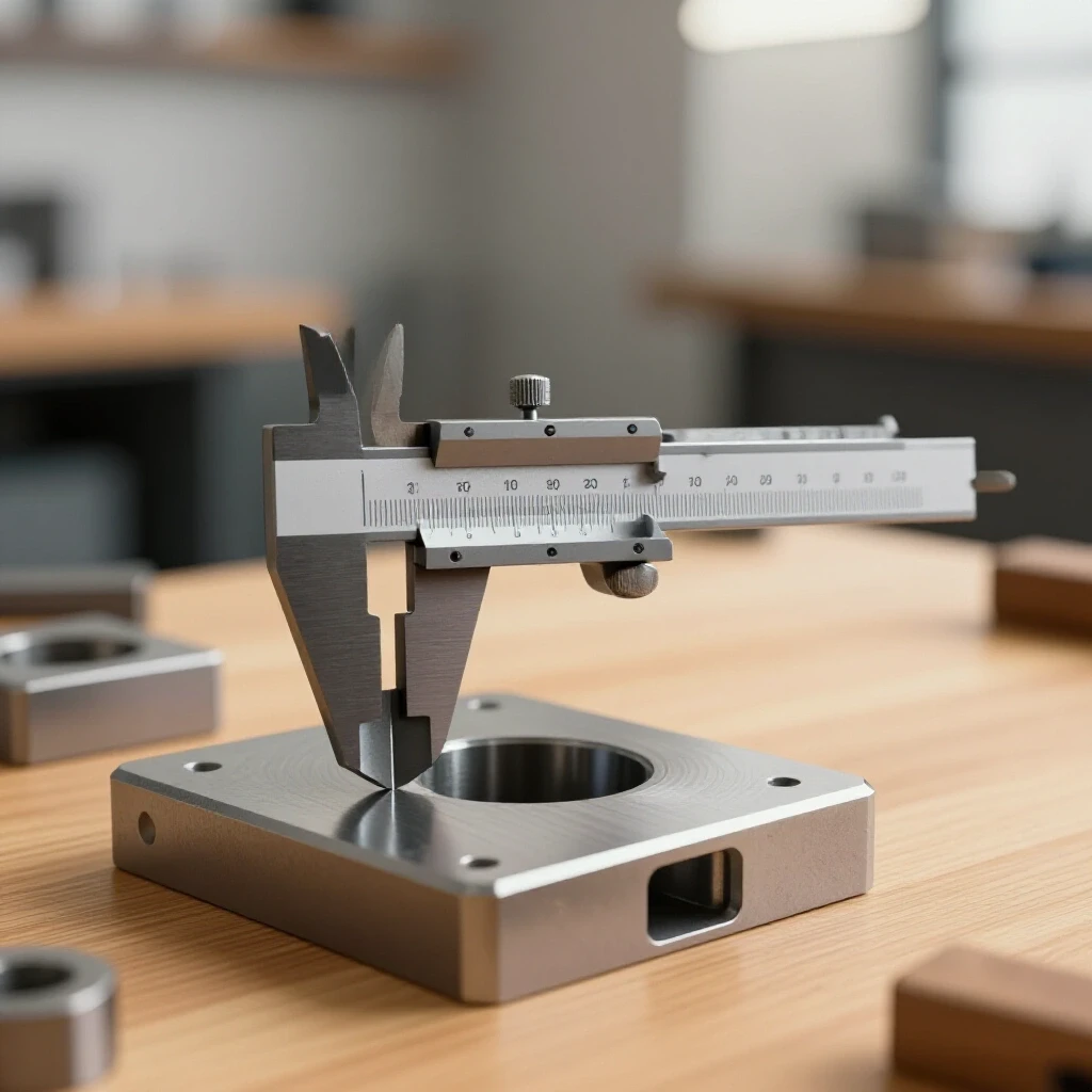
In my workshop, I use a pair of large vernier calipers for this task. I measure the distance between two rails at the start, the middle, and the end. If the numbers vary by more than my allowed tolerance, I know the rails are either “toeing in” or “flaring out.” This kind of error can cause mechanical binding and increase the wear on your components.
Another old-school trick is using a “go/no-go” gauge. This can be as simple as a piece of scrap metal cut to the exact width of the required gap. If the block fits snugly at one end but is loose at the other, you have found a parallelism error. This method is often faster and more intuitive than reading a digital display repeatedly.
- Measure at intervals: Don’t just check the ends; check every 12 inches.
- Use spacer blocks: A physical block provides immediate feedback on gap consistency.
- Check for “bowing”: Sometimes the ends are the right distance apart, but the middle of the bar is bent.
- Lock your calipers: Set your calipers to the desired width and use them as a fixed gauge.
Structural Load Considerations and Alignment
The way you align your joints directly impacts the structural metal load capacity of the finished piece. A joint that is perfectly square and tight-fitting allows for better weld penetration and a more uniform distribution of stress. Large gaps caused by poor alignment force the weld to act as a structural bridge, which is not its primary purpose.
When I inspect a joint, I look for “fit-up.” If the gap is too wide, the welding gas flow rate might not be enough to shield the entire molten pool, leading to porosity. Porosity is like Swiss cheese inside your weld; it looks solid on the outside but is full of tiny holes that weaken the joint. Proper alignment ensures the gap is consistent, usually around 1/16 to 1/8 of an inch for a structural butt weld.
Furthermore, consider the safety factor. If you are building something that will hold weight above people’s heads, you should aim for a 4:1 safety factor. This means the structure is four times stronger than the maximum load it will ever carry. Proper alignment is the first step in reaching that safety margin. If the structure is crooked, you have already eaten into that safety factor before you even finish the first weld.
Final Inspection Checklist for Fabricated Parts
Before you call a project finished, a final systematic inspection is required. This is the moment to catch any errors that might have occurred during the final cooling phase. Metal shrinks as it cools, and the forces involved are strong enough to bend thick steel plates.
I use a formal checklist to ensure I don’t miss anything. This includes checking all critical dimensions, verifying squareness in three dimensions, and looking for any signs of weld distortion. If a part has moved out of tolerance, now is the time to decide if it can be corrected or if it needs to be rebuilt. It is a hard choice to make, but it is better than a structural failure in the field.
- Check Overall Dimensions: Use a calibrated tape measure to verify length, width, and height.
- Verify Squareness: Check all corners with a machinist square or the 3-4-5 method.
- Check for Wind: Sight across the project to ensure no twisting has occurred.
- Inspect Weld Profiles: Ensure welds are consistent and free of undercut or overlap.
- Test Fit Components: If the project has mounting holes or moving parts, test them now.
- Document the Results: Keep a log of your measurements for future reference and quality control.
Building something with your own hands is rewarding, but it comes with the responsibility of ensuring it is safe. By focusing on the fundamentals of alignment and using the right manual tools, you can eliminate the guesswork from your fabrication. Precision isn’t just about the numbers; it’s about the confidence that your work will stand up to the forces it was designed to handle.
Frequently Asked Questions
How do I know if my machinist square is still accurate?
You can check a square using the “line flip” method. Place the square against a straight edge and draw a thin line. Flip the square over to the other side of the line. If the square’s edge does not perfectly align with the line you just drew, the square is out of “truth” and needs to be replaced or recalibrated.
What is the most accurate way to measure large frames?
For frames larger than four feet, checking the diagonals is the most reliable method. Measure from the top-left corner to the bottom-right corner, then do the same for the other side. If the two measurements are identical, the frame is square. This is often more accurate than using a small square at the corners.
Why does my frame pull out of square after I weld it?
This is caused by thermal expansion and contraction. As the weld bead cools, it shrinks and pulls the metal toward the weld. To prevent this, use stout tacks, weld in short segments, and alternate sides to balance the heat input. Clamping the part to a heavy table can also help resist these forces.
Can I use a standard level to check for square?
A level only tells you if a part is “plumb” (vertical) or “level” (horizontal) relative to the earth’s gravity. It does not necessarily mean the parts are square to each other. If your workbench is tilted, a level will give you a false reading. Always use a square to check the relationship between two parts.
What should I do if I find a twist in my frame after welding?
Small twists can sometimes be corrected using “flame straightening” or mechanical force (like a hydraulic press). However, these methods require experience to avoid damaging the metal’s internal structure. If the twist is significant, it is usually safer to cut the joints and re-weld the frame correctly.
How much of a gap is acceptable in a joint before welding?
Ideally, a structural joint should have a gap no larger than 1/8 of an inch. If the gap is too large, the weld will be prone to excessive shrinkage and internal stress. Large gaps also increase the risk of burn-through and poor penetration, which compromises the structural metal load capacity.
Is a digital angle finder better than a manual square?
Digital angle finders are convenient but can lose calibration or give false readings if the battery is low. Manual machinist squares are “fixed” tools that do not change. For the highest reliability in a shop environment, a manual square is generally preferred for verifying 90-degree angles.
How do I check if two long tubes are parallel?
The best way is to use a set of calipers to measure the distance between them at multiple points. You can also use “parallel blocks” or precisely cut spacers. If you can slide a spacer block between the tubes from one end to the other without it getting stuck or becoming loose, they are parallel.
(This article was written by one of our staff writers, James Harlan. Visit our Meet the Team page to learn more about the author and their expertise.)