How to Weld a Heavy-Duty Caster Base for Tool Cabinets (Fix)
I remember the first time I built a mobile foundation for a 500-pound tool chest. I spent hours measuring, cutting, and degreasing the steel. I clamped everything down, ran my beads, and felt like a pro. Then, I released the clamps. The frame didn’t just sit there; it sprang up an inch off the floor on one corner. It looked like a potato chip made of structural steel.
That project taught me a hard lesson: steel is alive. When you hit it with several thousand degrees of heat, it moves, pulls, and shrinks. After 13 years as a prototype technician, I’ve learned that building a straight, functional rolling platform isn’t about luck. It’s about understanding weld sequencing, managing heat distortion, and using the right layout fixtures. If you’ve ever watched a square frame warp into a trapezoid, this guide is for you. We are going to walk through the process of fabricating a rugged, reinforced base that stays flat and handles the weight of your heaviest shop equipment.
Designing the Foundation: Blueprints and Material Selection
Planning a structural frame requires a clear understanding of the loads it will carry and how the metal will react to being cut and joined.
Before I even strike an arc, I start with a detailed cut list. For a heavy shop cabinet, I prefer 2-inch by 2-inch square tubing with a 3/16-inch wall thickness for the main frame. For the areas where the wheels actually attach, I never use anything thinner than 1/4-inch plate steel. Thin metal flexes under the leverage of a caster, leading to “oil-canning” or eventual fatigue cracks.
Why Material Thickness Matters for Stability
Using 1/4-inch plate for caster mounts ensures the mounting bolts don’t pull through the metal and the base doesn’t bow. When you have 800 pounds of tools sitting on four points, that pressure is concentrated. A thicker plate distributes that load across a larger area of the frame.
Calculating the Kerf Allowance
One of the biggest mistakes I see in garage builds is ignoring the “kerf.” The kerf is the width of the material removed by the cutting tool. If you use a standard abrasive chop saw, you’re losing about 1/8-inch of metal with every cut. If you have four cross-members and you don’t account for that 1/8-inch, your final frame will be 1/2-inch too short.
- Abrasive Saw Kerf: 0.125 inches
- Cold Saw Kerf: 0.090 inches
- Plasma Cutter Kerf: 0.040 to 0.060 inches
- Bandsaw Kerf: 0.025 to 0.035 inches
Table 1: Material Selection for Heavy-Duty Shop Bases
| Component | Recommended Material | Why? |
|---|---|---|
| Main Perimeter | 2″ x 2″ x 3/16″ Square Tube | Balances weight and torsional rigidity. |
| Caster Plates | 1/4″ A36 Steel Plate | Prevents bending under point-load stress. |
| Cross Braces | 1.5″ x 1.5″ x 3/16″ Angle | Provides shelf for cabinet to sit in. |
| Corner Gussets | 3/16″ Flat Bar | Prevents “parallelogramming” of the frame. |
The Layout Phase: Creating a True Reference Surface
A layout is the process of marking and positioning your workpieces accurately before any permanent joining happens.
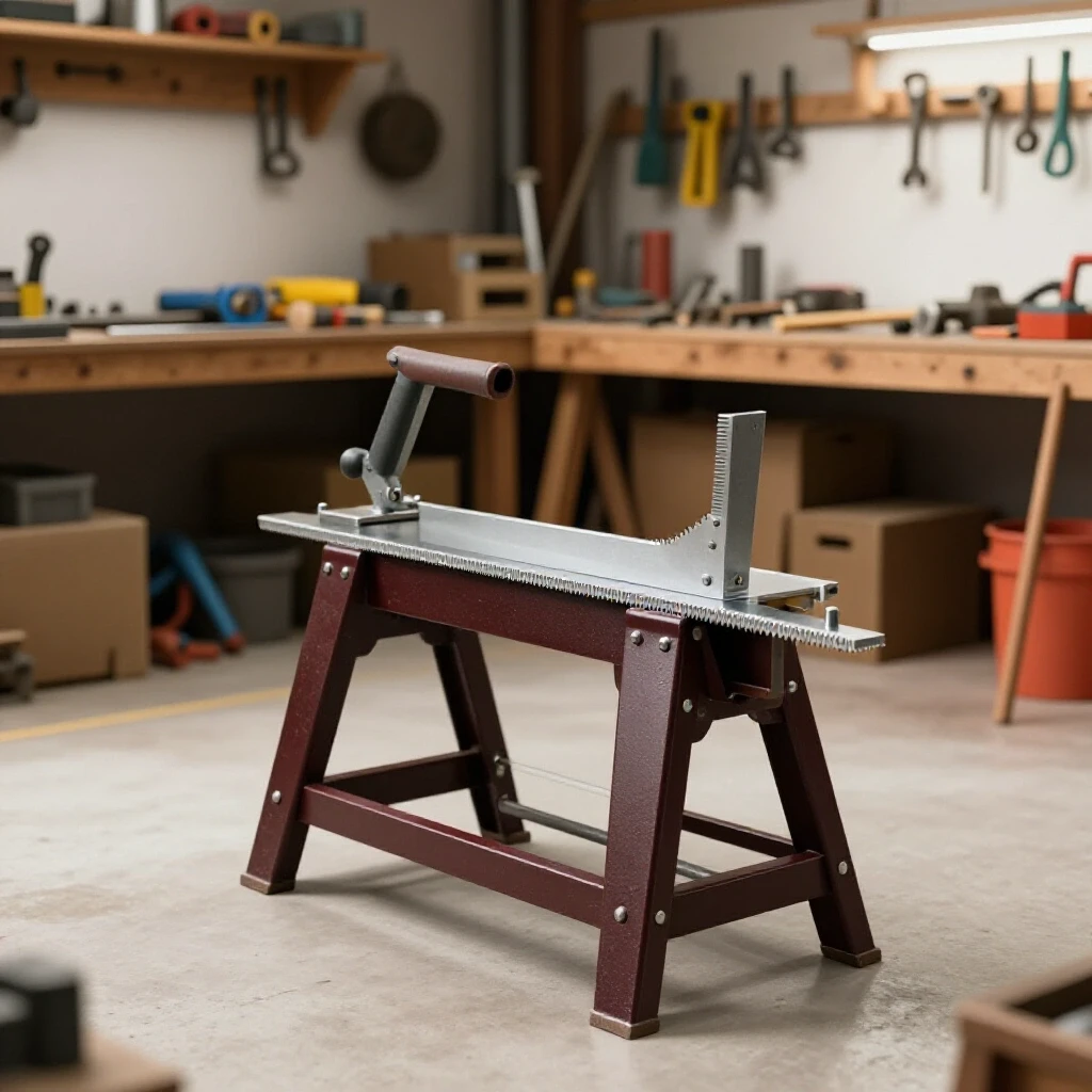
You cannot build a straight frame on an uneven concrete floor. Most garage floors are pitched for drainage, which means if you build your base there, you’re building a twist into the structure from the start. I use a dedicated welding table, but if you don’t have one, you can use two sawhorses and two lengths of heavy I-beam or thick-walled rectangular tubing to create a level “ladder” to work on.
Using Workshop Jigs and Fixtures
I rely heavily on “third-hand” tools. Simple L-shaped jigs made from scrap angle iron can help hold your corners at 90 degrees. I also use “fences” or stops tacked directly to my table to keep the frame pieces from sliding as I tighten my clamps.
The 3-4-5 Rule for Squareness
To ensure your frame is square, use the Pythagorean theorem. Measure 3 inches from a corner on one side and 4 inches on the other. The diagonal distance between those two points should be exactly 5 inches. For larger frames, use 18, 24, and 30 inches. If your diagonals are equal, your frame is square. I aim for a tolerance of +/- 1/16th of an inch across the diagonals.
Managing Metal Warping: The Physics of Weld Shrinkage
Weld shrinkage is the natural contraction of metal as it cools from a molten state to room temperature.
When you lay a bead of weld, the liquid metal occupies more volume than it does when it’s solid. As it cools, it pulls the surrounding base metal toward the center of the weld. If you weld only on one side of a joint, the metal will “pull” in that direction, creating an angular distortion. Understanding this “pull” is the secret to keeping your project flat.
Tack Welding Strategies
A tack weld is a small, temporary weld used to hold parts in place. I see many beginners make tacks that are too small. For a heavy base, your tacks should be about 1/2-inch long and placed at every corner. I follow a specific “star” pattern for tacking, similar to how you tighten lug nuts on a car. This distributes the initial heat evenly.
- Place a tack on the inside corner of Joint A.
- Move to the opposite corner (Joint C) and tack the inside.
- Check for square.
- Tack the outside corners in the same cross-pattern.
Tack Spacing and Size
For 3/16-inch tubing, I place a tack every 2 inches if I’m doing a long seam. For the corner joints of a caster base, four tacks per joint (top, bottom, and both sides) are mandatory before you start the final beads.
The Weld Sequence: Controlling the Heat
Weld sequencing is the specific order in which you apply your final welds to balance the internal stresses of the metal.
If you start at one corner and weld all the way around the frame in a circle, you are asking for trouble. By the time you get back to the start, the cumulative “pull” will have twisted the frame into a diamond shape. I use a technique called “balanced welding.”
The Balanced Sequencing Method
Building on the tacking pattern, I weld in short segments. Instead of one long 2-inch bead, I might do 1 inch, move to the opposite side of the frame, do 1 inch there, and let the first side cool. This prevents any one area from getting so hot that it loses its structural integrity and warps.
Table 2: Weld Sequencing and Distortion Control
| Step | Action | Purpose |
|---|---|---|
| 1 | Corner Tacks (Inner) | Sets the initial squareness. |
| 2 | Corner Tacks (Outer) | Locks the joint against “opening up.” |
| 3 | Vertical Down Beads | Seals the sides with lower heat input. |
| 4 | Flats (Alternating) | Balances the “pull” across the top and bottom. |
| 5 | Caster Plate Fillets | Heavy welds done last to prevent frame twist. |
Back-Stepping for Long Seams
If you are welding a long reinforcing plate to the frame, use the “back-step” method. Instead of welding from left to right, you start 2 inches in from the right and weld toward the right edge. Then you move 4 inches in and weld toward the start of your first bead. This directs the shrinkage forces against each other, cancelling out much of the warp.
Structural Integrity: Fillet Weld Sizing and Penetration
A fillet weld is a triangular weld that joins two surfaces at an angle, typically 90 degrees.
For a heavy-duty rolling base, the size of your weld “leg” should roughly match the thickness of the thinnest piece of metal you are joining. If you are welding 1/4-inch caster plates to 3/16-inch tubing, your weld bead should have a 3/16-inch leg. Any larger is a waste of wire and adds unnecessary heat; any smaller may not provide enough strength to support the weight.
Ensuring Deep Penetration
I often see “cold” welds where the metal just sits on top of the surface like a bead of caulk. To fix this, I make sure I have a slight gap (about 1/16-inch) between my parts. This “root opening” allows the weld to penetrate all the way through the metal, creating a much stronger bond. If you’re using a MIG welder, ensure your wire speed and voltage are dialed in so you get that “frying bacon” sound, which indicates a stable arc and good fusion.
Caster Attachment Points
When welding the plates that will hold your wheels, avoid welding all four sides in one go. The plate will “cup,” making it impossible for the caster to sit flat. I weld two opposite sides, let them cool to the touch, and then weld the remaining two sides. This keeps the mounting surface as flat as possible.
Correcting Distortion: What to Do When It Warps
Even with the best planning, metal sometimes moves in ways we don’t want.
If you find that your frame has a slight rock (one corner is high), you can often fix it with a “heat shrink.” This involves heating a small spot on the side opposite the warp with an oxy-acetylene torch until it’s cherry red, then quenching it with a wet rag. The rapid cooling pulls the metal back. However, it’s much easier to prevent the warp than to fix it.
Using Clamps as Restraints
I keep my frame clamped to the table until the metal is cool enough to touch with a bare hand. If you release the clamps while the metal is still “blue” hot, the internal stresses will win every time. Think of the clamps as a cage for a wild animal; you don’t open the door until the animal has calmed down.
Checking Dimensional Tolerances
Once the frame is cool, I perform a final check. I use a digital angle finder to ensure the caster plates are level with each other. If one plate is tilted, the wheel will not swivel correctly, leading to a cabinet that is hard to push and “darts” in different directions.
Build Log: The “Heavy Storage” Base Project
I recently built a base for a 1,200-pound engine part cabinet. Here is the breakdown of that build to show how these principles apply in the real world.
- Preparation: I cut four pieces of 2x2x3/16 tubing. I accounted for a 1/8-inch kerf by adding it to my total measurements.
- The Jig: I clamped two 4-foot levels to my table to act as a straightedge.
- The Tacks: I used 1/8-inch 7018 stick electrodes for deep-penetrating tacks. I checked squareness after every two tacks.
- The Sequence: I welded the top flats of all four corners first, moving in a diagonal pattern. I then flipped the frame and did the bottoms.
- The Result: After cooling, the frame was within 1/32-inch of perfectly flat across a 48-inch span.
Cost Tracking for the Project: * Steel Tubing (12ft): $65.00 * 1/4″ Plate Scraps: $15.00 * Welding Consumables: $10.00 * Total Time: 3.5 hours
Common Pitfalls for Garage Builders
I’ve seen many talented DIYers get frustrated because they skip the “boring” parts of fabrication.
- Rushing the Cooling: Never throw a bucket of water on a hot frame to speed things up. This can make the steel brittle and cause extreme warping.
- Poor Fit-Up: If you have big gaps in your joints, the weld has to fill that space. More weld metal equals more heat, and more heat equals more warp. Grind your cuts until they fit tight.
- Ignoring Mill Scale: That dark grey coating on new steel is an insulator. It messes with your arc and leads to weak welds. Always grind the mill scale off until you see shiny “white” metal before welding.
Advanced Tools for the Modern Shop
While a square and a tape measure are the basics, new technology can help you achieve better results.
- Laser Alignment Levels: I use a cross-line laser to project a perfectly level line across my work area. This helps me see if a frame is twisting in real-time.
- 3D Printed Layout Jigs: For complex angles, I sometimes 3D print a “sleeve” that slides over the tubing to show me exactly where to cut or tack.
- Aluminum Heat Sinks: If I’m worried about a thin area warping, I clamp a thick block of aluminum next to the weld. Aluminum sucks heat away much faster than steel, protecting the surrounding area.
Summary of Key Metrics for a Durable Base
- Minimum Plate Thickness: 1/4-inch for caster mounts.
- Squareness Tolerance: +/- 1/16-inch across diagonals.
- Tack Size: 1/2-inch long for 3/16-inch wall tubing.
- Weld Leg Size: Equal to the thickness of the thinnest material.
- Cooling Time: Wait until the metal is below 120°F before removing clamps.
Fabricating a heavy-duty rolling foundation is a test of patience and process. By respecting the physics of heat and taking the time to set up a proper layout, you can build shop furniture that lasts a lifetime. The goal isn’t just to stick two pieces of metal together; it’s to create a structural tool that makes your workspace more efficient and your projects easier to handle.
FAQ: Frequently Asked Questions About Heavy-Duty Fabrications
Why does my frame always twist even when I clamp it to a heavy table? Clamps can only hold so much force. As a weld cools, the shrinkage force can actually be strong enough to bend your welding table if the table isn’t thick enough. To prevent this, focus on balanced sequencing—welding on the opposite side of the previous weld to “pull” the frame back into alignment.
Can I use a 110V MIG welder for 1/4-inch caster plates? Most 110V welders struggle to get deep penetration on 1/4-inch steel. If you must use one, pre-heat the steel with a propane torch to about 200°F and use a flux-core wire, which generally penetrates deeper than solid wire with gas.
How do I know if my weld is strong enough to hold a 1,000-pound cabinet? Look for “wetting” at the edges of the weld. The bead should look like it has melted into the base metal, not just sitting on top. A 1-inch long, 3/16-inch fillet weld can technically hold thousands of pounds in shear, so as long as you have good penetration on all four corners, the steel will likely fail before the weld does.
What is the best way to ensure the casters are perfectly level? Weld your plates last. After the main frame is built and cooled, place the frame on a known flat surface. Use shims to get the frame level, then slide your plates underneath and tack them. This accounts for any slight variations in the frame tubing.
Should I weld the inside or the outside of the tube joints? For maximum strength, you should weld both. However, if you are worried about the cabinet fitting inside the frame, you might only weld the outside and the top/bottom. If you only weld one side, the joint will “pull” toward the weld, so always try to balance the welds on both sides of the tube.
How big should my tack welds be? For structural shop projects, a tack should be about 2 to 3 times the thickness of the metal. For 3/16-inch tubing, a 1/2-inch tack is perfect. It needs to be strong enough to resist the shrinking forces of the first few inches of the final bead.
What happens if I use 1/8-inch plate instead of 1/4-inch for the wheels? Over time, the constant stress of moving the cabinet will cause the 1/8-inch plate to flex. This leads to “metal fatigue,” and eventually, the plate will crack or the bolts will pull through. For anything mobile and heavy, 1/4-inch is the industry standard for a reason.
How do I calculate the diagonal measurement to check for square? Use the formula: A² + B² = C². If your frame is 24 inches by 36 inches: (24×24) + (36×36) = 576 + 1296 = 1872. The square root of 1872 is approximately 43.26 inches. If both diagonals measure 43-1/4 inches (roughly), you are square.
Is MIG or Stick welding better for this type of project? MIG is faster and cleaner, making it great for garage builds. Stick welding (SMAW) is often better for outdoor work or when welding through mill scale and rust. Both are perfectly capable of building a heavy-duty base if the settings are correct.
Should I grind my welds flat? Only if you need a flush surface for the cabinet to sit on. Grinding a weld removes material and can weaken the joint if you grind too deep into the “throat” of the weld. If you must grind, try to only remove the “hump” and leave the metal in the corner intact.
(This article was written by one of our staff writers, Robert Kline. Visit our Meet the Team page to learn more about the author and their expertise.)