How to Weld a Sturdy I-Beam Chain Hoist Trolley (DIY Guide)
Moving a two-ton 1940s engine lathe across a crowded workshop is a task that demands respect for physics and a deep understanding of structural integrity. In my 18 years of vintage machinery restoration, I have learned that the tools we build to manage our “rescues” are just as important as the machines we are reviving. Whether you are extracting a seized drill press from a damp basement or repositioning a massive cast-iron bandsaw, a custom-built overhead carriage is often the only way to navigate tight spaces safely.
I remember my first major project, a 1932 Hendey lathe that had spent decades sinking into a dirt floor. The sheer weight of the cast iron was intimidating, and standard shop jacks simply couldn’t provide the precision needed to lift it onto a trailer without risking a crack in the fragile legs. That experience taught me that a shop-built trolley, tailored to the specific dimensions of your overhead I-beam, is an essential piece of infrastructure for any serious restorer. It allows for the controlled, incremental movements necessary when you are dealing with brittle, aged metal and obsolete fastener patterns that cannot be easily replaced.
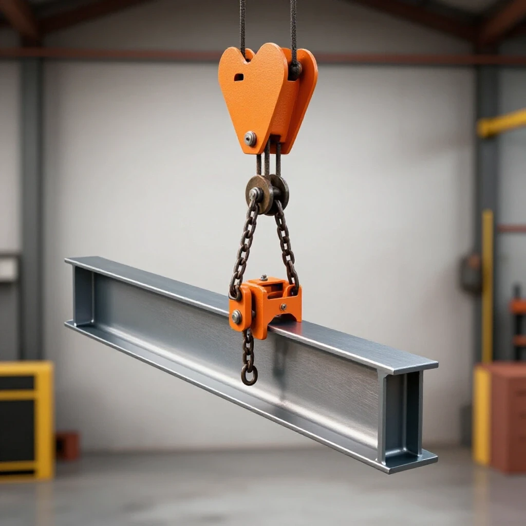
Building your own lifting hardware requires a blend of mechanical engineering and careful fabrication. It is not a project to be rushed. When we are restoring classic cast iron, we often focus on the fine details of hand scraping or babbitt bearing pouring, but the “heavy lifting” phase is where the most risk resides. A well-welded trolley ensures that your focus remains on the restoration itself, rather than the fear of a structural failure during a move.
Evaluating Structural Steel and Beam Profiles for Workshop Lifting
Selecting the right materials for a shop-built overhead carriage involves analyzing the beam’s flange width, thickness, and the physical properties of the steel plate used for the side brackets. This stage ensures the final assembly can handle the dead weight of heavy machinery without deforming or binding during travel.
Before you strike an arc, you must assess the “track” your trolley will run on. In many older shops, I-beams might have surface pitting or slight twists from decades of use. I always start by cleaning the beam flanges with a wire wheel to check for structural thinning. If you are working with a S-beam (standard American beam) or a W-beam (wide flange), the slope of the flange will dictate the taper of your trolley wheels. Using flat wheels on a tapered flange leads to point-loading, which can cause the metal to fatigue and eventually fail.
Understanding Load Paths and Steel Thickness
Load paths refer to the route that weight travels from the chain hoist hook through the trolley frame and into the I-beam. Proper steel thickness prevents the side plates from “flaring” outward under the stress of a heavy machine like a vintage milling machine or a large surface grinder.
For most hobbyist restoration shops, using 1/2-inch or 5/8-inch thick A36 structural steel plate for the side carriages provides a necessary safety margin. When I built the trolley for my shop’s main 6-inch I-beam, I opted for 1/2-inch plate to ensure the axle holes wouldn’t ovalize over time. You must also consider the “throat” of the trolley—the space between the side plates. It needs to be wide enough to clear the beam’s widest point but narrow enough to keep the wheels centered on the load-bearing tracks.
Common Steel Profiles for Shop Fabrication
| Component | Material Recommendation | Purpose |
|---|---|---|
| Side Plates | 1/2″ A36 Steel Plate | Provides the main structural frame for the wheels and hoist mount. |
| Load Pin | 1″ to 1.25″ 4140 Alloy Steel | The central pivot point where the chain hoist attaches. |
| Spacers | Schedule 80 Steel Pipe | Maintains the distance between side plates and prevents crushing. |
| Gussets | 3/8″ Steel Plate | Reinforces the corners where the side plates meet the load pin housing. |
Removing Machinery Rust and Preparing Steel for Welding
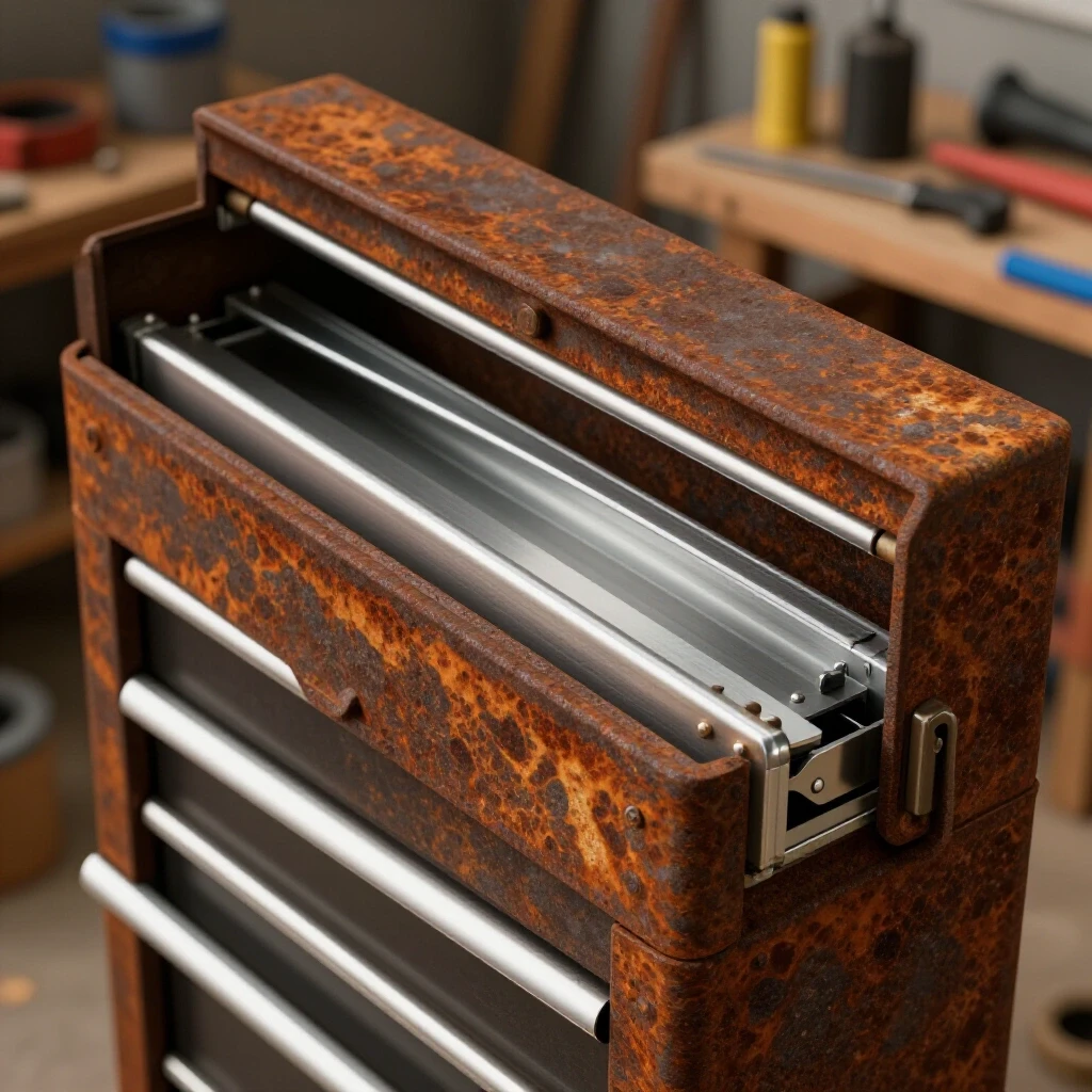
Effective metal preparation involves removing all contaminants, including mill scale, deep-seated rust, and old oils, to ensure a high-quality weld. For restorers, this often means using a combination of mechanical grinding and chemical treatments to reach clean, virgin metal.
When you source steel plate from a local yard, it is usually covered in mill scale—a bluish-black layer of iron oxide formed during the rolling process. Welding over mill scale is a recipe for porosity and cold-lapping, which can lead to a catastrophic failure of your lifting gear. I treat my new steel much like I treat the parts during a vintage machinery restoration: I strip it down to the bare essentials.
Chemical vs. Mechanical Cleaning Methods
Mechanical cleaning with a flap disc is fast, but for complex shapes or heavily rusted salvaged plate, chemical methods are often more thorough. I frequently use a 12V DC electrolysis bath for smaller components, but for large trolley plates, a phosphoric acid-based rust chelator works wonders. It converts the oxide into a stable phosphate coating that can be easily sanded off before welding.
- Electrolysis: Best for deep rust removal in threaded holes or axle bores.
- Angle Grinder (36-60 grit): Necessary for removing the thick mill scale on new plate.
- Acetone Wipe: The final step to remove skin oils and shop dust before the first tack weld.
Why Clean Metal Matters for Structural Integrity
In the world of machine disassembly tips, we often talk about “cleanliness being next to godliness.” This is doubly true for structural welding. A weld is only as strong as its penetration into the base metal. If you leave rust or scale in the joint, the weld sits on top of the contaminant rather than fusing with the steel. When you are suspended a 3,000-pound lathe in the air, that lack of fusion is a silent killer.
Designing the Carriage and Axle Geometry
Axle geometry and wheel alignment determine how smoothly the trolley moves along the beam and how evenly the weight is distributed. Precision in this stage prevents the trolley from “crabbing” or jamming, which can cause dangerous swinging of the suspended load.
In my experience, the most common mistake in DIY lifting gear is poor wheel alignment. If your axles are even 1/16th of an inch out of parallel, the trolley will fight itself. It will want to climb the flange of the I-beam, creating massive friction and potentially damaging the beam itself. I use a machinist’s square and a height gauge to mark my axle holes on both side plates simultaneously.
Selecting Wheels and Bearing Clearances
When restoring classic tools, we often deal with babbitt bearing pouring or sleeve bearing service. For a trolley, however, sealed ball bearings are the standard. The wheels should be machined with a slight taper if you are using a standard S-beam. The bearing clearance on the axle should be tight—typically around 0.001 to 0.002 inches—to prevent the wheels from wobbling.
- Measure the flange width of your beam at three different points.
- Calculate the total width of the trolley, including the wheels and a 1/8-inch “float” on either side.
- Source wheels with integrated bearings rated for at least double your expected maximum load.
- Ensure the axle material (like 4140 or 1045 cold-rolled steel) matches the inner diameter of the bearings perfectly.
The Importance of the Load Pin Position
The load pin is the heart of the assembly. It must be positioned exactly in the center of the wheelbases to ensure the weight is balanced. If the pin is offset, one set of wheels will carry more load than the other, leading to premature wear and uneven travel. I prefer to use a “dropped” load pin design, where the attachment point for the chain hoist sits below the axles, lowering the center of gravity and increasing stability.
Welding the Structural Frame and Reinforcements
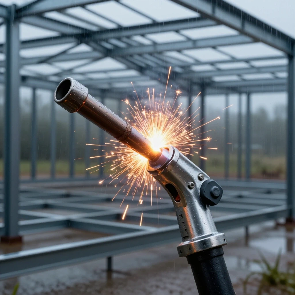
Welding a load-bearing assembly requires specific techniques to ensure deep penetration and a lack of defects like undercut or slag inclusions. Using the correct welding process and rod selection is critical for the safety of the final product.
For this type of structural work, I rely on the 7018 low-hydrogen electrode or a high-quality MIG setup with a gas shield. The 7018 is the “gold standard” for structural welding because it produces a ductile weld that can withstand the vibrations and shocks of moving heavy machinery. When I was rebuilding the base of a 1920s radial arm drill, I used these same welding principles to ensure the new steel could support the massive cast-iron column.
Step-by-Step Welding Sequence
- Tack Welding: Place small tacks at the four corners of the assembly. Check for squareness and ensure the side plates are perfectly parallel.
- Root Pass: Run a deep-penetrating bead at the base of the joint. If you are welding 1/2-inch plate, a multi-pass fillet weld is mandatory.
- Gusset Attachment: Weld 3/8-inch triangular gussets to the areas where the side plates meet the cross-members. This prevents the plates from “parallelogramming” under load.
- Cooling: Never quench a structural weld in water. Let it cool slowly in the air to avoid embrittlement.
Comparison of Welding Processes for Shop Fabrication
| Process | Pros | Cons | Best Use |
|---|---|---|---|
| SMAW (Stick) | Deep penetration, works on thicker steel, 7018 is very strong. | Requires more skill to manage slag, slower than MIG. | Heavy structural plates and gussets. |
| GMAW (MIG) | Fast, clean, easy to see the puddle. | Requires gas shielding, can have “cold start” issues on thick plate. | Tacking and smaller reinforcement tabs. |
| GTAW (TIG) | Most precise, cleanest welds, no slag. | Very slow, requires extreme cleanliness, expensive. | Precision axle caps or thin-walled spacers. |
Precision Alignment and Final Assembly
Final assembly is the process of bringing all fabricated components together, ensuring that moving parts rotate freely and that the structural frame remains true. This stage often involves fine-tuning tolerances and verifying that all fasteners are secured against vibration.
Once the welding is complete and the metal has cooled, I always re-check the alignment. Heat from welding can warp even 1/2-inch steel. If the plates have pulled inward, you may need to use a hydraulic jack to carefully push them back to parallel. This is where your skills in classic tool alignment come into play. Just as you would align the headstock of a lathe to the bedways, you must align the trolley wheels to the I-beam.
Using Spacers for Adjustability
I highly recommend using a series of thick washers or machined spacers on the central load pin. This allows you to adjust the width of the trolley if you ever move to a shop with a different sized I-beam. During a vintage machinery restoration, we often have to fabricate legacy parts; think of these spacers as “custom shims” for your shop infrastructure.
- Inner Spacers: These set the minimum width of the trolley.
- Outer Spacers: These hold the side plates against the load pin nuts.
- Locking Mechanism: Use Grade 8 bolts and nyloc nuts, or better yet, drill the load pin for a heavy-duty cotter pin or castle nut.
Verifying Wheel Travel and Bearing Seat
Before putting a load on the trolley, roll it back and forth across the entire length of the beam. Listen for any clicking or grinding. If the trolley feels “tight” in certain spots, check the beam for paint buildup or old grease. I once spent three hours cleaning 50 years of hardened sawdust and oil off a beam just to get a trolley to roll smoothly.
Integrating the Trolley into the Restoration Workflow
A functional overhead hoist system changes how you approach a machine rescue. It allows for safer disassembly of heavy components, like removing a 500-pound milling machine head or lifting a heavy cast-iron base for cleaning.
With the trolley installed, you can now perform tasks that were previously dangerous or impossible. For example, when removing machinery rust in a large electrolysis tank, you can use the hoist to slowly lower the part into the solution and, more importantly, lift it out safely once the cycle is complete. No more straining your back or risking a drop that could shatter a rare casting.
Case Study: Rebuilding a 1940s Vertical Mill
When I restored a 1947 vertical mill, the trolley was the unsung hero. I used it to: 1. Lift the motor and drive assembly (approx. 250 lbs) to inspect the sleeve bearings. 2. Suspend the main table while I performed machinery hand scraping on the saddle ways. 3. Hold the heavy knee in place while I replaced the obsolete lead screw with a modern equivalent.
By having a reliable, shop-built lifting system, I was able to maintain 10–20 PPI (points per inch) of scraping density because I wasn’t rushed or fatigued by the physical labor of moving the parts manually.
Maintenance Checklist for Shop-Built Lifting Gear
- Monthly Inspection: Check welds for any signs of cracking or “spider-webbing” in the paint.
- Lubrication: Apply a light machine oil to the wheel bearings (if not sealed) and the load pin threads.
- Beam Check: Ensure the I-beam end-stops are secure. You don’t want your trolley rolling off the end of the beam!
- Load Test: Periodically lift a known weight (like a stack of weights or a heavy engine block) to ensure nothing has shifted or bent.
Safety Protocols and Load Awareness
Operating a shop-built trolley requires a constant awareness of weight limits and the behavior of suspended loads. Safety is not a one-time setup but a continuous practice that involves inspecting gear before every lift.
Never exceed the estimated capacity of your weakest link. If your I-beam is only rated for 1 ton, it doesn’t matter if your trolley can hold 5 tons. Always work within the limits of your shop’s structure. In my 18 years, I have seen more accidents caused by “just this one quick lift” than by any other factor.
- Avoid Side Loading: Only lift loads that are directly underneath the trolley. Pulling from an angle puts immense stress on the side plates and can cause the trolley to derail.
- Clear the Area: Never stand directly under a suspended load. Even the best-welded trolley can be undone by a failing chain hoist or a snapped strap.
- Use Soft Slings: When lifting restored cast iron, use nylon slings rather than chains to avoid marring the freshly painted or scraped surfaces.
FAQ: Frequently Asked Questions about DIY Shop Trolleys
What is the best steel to use for a shop-built trolley? A36 structural steel is the standard for the side plates because it is easy to weld and has predictable strength. For the axles and load pins, 4140 alloy steel is preferred because of its higher tensile strength and resistance to bending.
Can I use a MIG welder for this project? Yes, provided your MIG welder has the amperage to handle 1/2-inch plate. You must ensure you are getting deep penetration. If you are unsure, a stick welder with 7018 rods is a more “forgiving” choice for thick structural joints.
How do I know if my I-beam can support the weight? You must consult a structural beam chart. For example, a standard 6-inch S-beam over a 10-foot span can typically support around 2,000 to 3,000 pounds, but this depends heavily on how the beam is supported at the ends.
Should I paint my trolley? Yes, but only after a thorough inspection of the welds. Use a high-visibility color like safety orange or yellow. Do not paint the wheel treads or the I-beam flange, as this can cause the wheels to slip or create a gummy residue that hinders movement.
What kind of bearings should I use in the wheels? Deep-groove, sealed ball bearings are the best choice. They are protected from shop dust and metal shavings, which is essential in a restoration environment where grinding and sanding are common.
How do I calculate the “float” for the wheels? The “float” is the side-to-side play between the wheel flanges and the I-beam. A 1/8-inch total gap (1/16-inch per side) is usually sufficient to allow the trolley to move freely without allowing it to walk too far off-center.
Can I use salvaged steel for the side plates? Yes, but you must be extremely careful. Salvaged steel must be stripped of all rust and old paint. Inspect it for any existing cracks or “work hardening” from its previous life. If the steel is pitted, it may have lost significant structural thickness.
How do I prevent the trolley from “crabbing” on the beam? Crabbing happens when the axles aren’t parallel. Use a precision square during the tack-welding phase to ensure the side plates are perfectly aligned. If the trolley still crabs, you may need to shim one of the wheels.
What is the safest way to attach the chain hoist? A central load pin with a dedicated lifting shackle is the safest method. Ensure the pin is secured with a castle nut and cotter pin so it cannot vibrate loose during use.
Is it better to weld or bolt the trolley together? For a custom shop trolley, a fully welded frame (excluding the axles and load pin) is generally sturdier and less prone to loosening over time. Bolted assemblies require Grade 8 hardware and constant monitoring of torque specs.
How do I handle tapered I-beam flanges? You must use wheels that are specifically machined with a matching taper (usually 1:6 or about 9 degrees). Using flat wheels on a tapered flange will cause the weight to concentrate on the inner edge of the wheel, leading to failure.
What should I do if I hear a “pinging” sound while lifting? Stop immediately. A pinging sound often indicates a weld is cracking or the steel is reaching its elastic limit. Lower the load carefully and inspect the entire trolley and beam for signs of stress.
(This article was written by one of our staff writers, Richard Beaumont. Visit our Meet the Team page to learn more about the author and their expertise.)