How to Weld a Heavy Duty Trailer Ramp Gate Safely (Guide)
There is a specific kind of silence that fills a workshop when you are staring at a 1,500-pound piece of American history sitting on the back of a trailer. I remember bringing home my first 1940s South Bend lathe. It was a beautiful, rusted mass of cast iron that required more than just muscle to move; it required a structural solution. For those of us who rescue neglected machinery, the challenge often begins before the tool even touches the shop floor. We need reliable, heavy-duty equipment to bridge the gap between the trailer bed and the pavement.
Building a structural loading surface for these heavy machines is a project that demands the same precision we apply to scraping a bedway or pouring a babbitt bearing. When you are moving a top-heavy drill press or a solid iron milling machine, the gate at the back of your hauler cannot be an afterthought. It must be a rigid, engineered assembly capable of handling concentrated loads without deflection. Over the last 18 years, I have learned that a safe weld is not just about a pretty bead; it is about deep penetration, proper joint geometry, and a methodical approach to heat management.
Assessing Structural Requirements for Machine Transport
Before you strike an arc, you must understand the forces that a loading gate will endure. A heavy-duty ramp for workshop use must support static loads and the dynamic stress of a machine being winched upward. We generally design these structures for loads under 2,000 pounds, ensuring they can handle the weight of most vintage lathes, saws, and presses found in a home restoration shop.
Proper planning begins with material selection and load calculation. You are not just building a gate; you are building a bridge. This requires a focus on the “why” of structural integrity before the “how” of the welding process. We look at the span of the gate and the thickness of the steel to ensure the final product remains within safe operating tolerances.
Defining Load Limits and Material Thickness
Designing for a 2,000-pound limit requires a conservative approach to material selection. For most shop-built gates, 2-inch square mild steel tubing with a 3/16-inch wall thickness provides an excellent balance of weight and rigidity. Using thinner materials may lead to sagging, which can cause a heavy machine to shift unexpectedly during loading.
- Static Load: The weight of the machine when it is stationary on the ramp.
- Dynamic Load: The increased force applied as the machine moves or if the trailer bounces.
- Safety Factor: We typically aim for a 3:1 safety factor, meaning the structure is theoretically capable of holding three times the intended load.
Choosing the Right Steel for Structural Rigidity
In my experience, A36 mild steel is the gold standard for these projects. It is predictable, easy to weld with standard shop equipment, and offers the ductility needed to handle stress without cracking. Avoid using scrap metal of unknown origin, as high-carbon steels or alloys can become brittle after welding, leading to catastrophic failure under the weight of a cast-iron machine.
Preparing the Metal for High-Strength Joints
The success of a structural weld is determined long before you put on your helmet. Just as we must meticulously remove machinery rust from a vintage gear set before reassembly, we must strip mill scale and oxidation from our steel tubing. Contaminated joints lead to porosity, which acts like a hidden fracture inside your weld.
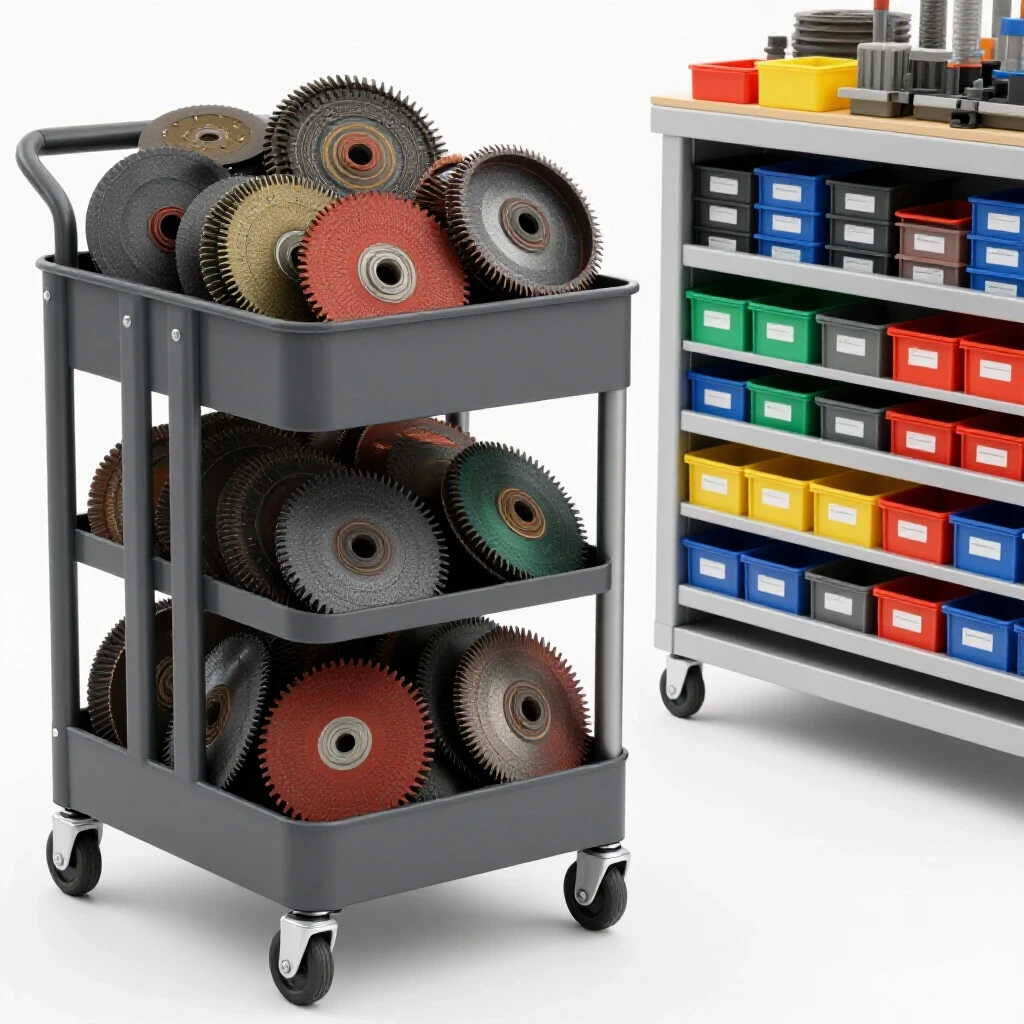
I treat every joint as if it were a critical machine component. This means using a flap disc to grind the mating surfaces down to bright, shiny metal. If the steel is salvaged or has heavy surface rust, I may even use a localized chemical bath or a wire wheel to ensure the weld pool is not compromised by impurities.
Why Joint Geometry Matters for Load Bearing
A simple butt joint is rarely sufficient for a loading gate. To achieve the necessary strength, we must create space for the weld metal to penetrate deep into the core of the steel. This is achieved by beveling the edges of the tubing at a 30 to 45-degree angle. This “V-groove” allows the filler metal to fuse the entire thickness of the wall, rather than just sitting on the surface.
- Root Gap: Leave a small space (about 1/16 to 3/32 inch) between the pieces to allow the weld to reach the back side.
- Tack Welding: Use small, strong welds at the corners to hold the assembly in square before committing to the full bead.
- Squareness Check: Use a machinist’s square to verify the frame is aligned to within 0.010 inches over a 12-inch span.
Cleaning and Degreasing Strategies
Any oil or grease left on the metal will vaporize under the heat of the arc, creating gas pockets in the weld. I use a dedicated degreaser or acetone to wipe down every joint. This is especially important if the steel was stored in a damp environment where a thin film of protective oil was applied at the mill.
| Preparation Step | Tool Required | Objective |
|---|---|---|
| Scale Removal | 60-Grit Flap Disc | Expose bright, virgin steel |
| Edge Beveling | Angle Grinder | Create a V-groove for 100% penetration |
| Degreasing | Acetone & Lint-free rag | Remove hydrocarbons and oils |
| Fit-up | Magnetic Squares | Ensure 90-degree alignment |
Selecting the Right Welding Process and Consumables
For fabricating shop infrastructure, you generally have two reliable choices: MIG (Metal Inert Gas) or Stick (Shielded Metal Arc Welding). Each has its place in the restorer’s toolkit. MIG is excellent for clean, fast work in a controlled shop environment, while Stick is the old-school workhorse that can handle slightly less-than-perfect metal and outdoor conditions.
In my shop, I prefer a high-quality MIG setup for ramp gates because of the control it offers on thinner wall tubing. However, if I am welding thicker plate for a hinge bracket, I might switch to a Stick welder with an E7018 electrode. This “low-hydrogen” rod provides excellent mechanical properties and a very strong finished weld that resists cracking under heavy vibration.
MIG Welding Settings for Structural Steel
When using MIG, your wire speed and voltage must be dialed in to ensure you aren’t just “cold lapping” the metal. Cold lap occurs when the weld metal melts but fails to fuse with the base metal. For 3/16-inch steel, I typically set my machine to a higher voltage range and use a 0.035-inch solid wire with a 75/25 Argon/CO2 shielding gas mix.
- Wire Feed Speed: Adjust until the arc sounds like “sizzling bacon.”
- Voltage: Ensure the puddle is fluid enough to wet into the edges of the joint.
- Travel Speed: Move slowly enough to allow the puddle to build, but fast enough to avoid burning through the tubing.
Stick Welding for Maximum Penetration
If you choose Stick welding, electrode selection is critical. For the root pass (the first weld in the joint), an E6010 or E6011 rod is excellent because it “digs” deep into the metal. For the final “cap” pass, an E7018 rod provides a smooth, strong finish. This two-step process ensures the joint is solid from the inside out.
- E6011: High penetration, handles rust well, but produces more splatter.
- E7018: High strength, low hydrogen, requires a dry storage environment.
Executing the Weld: Sequence and Technique
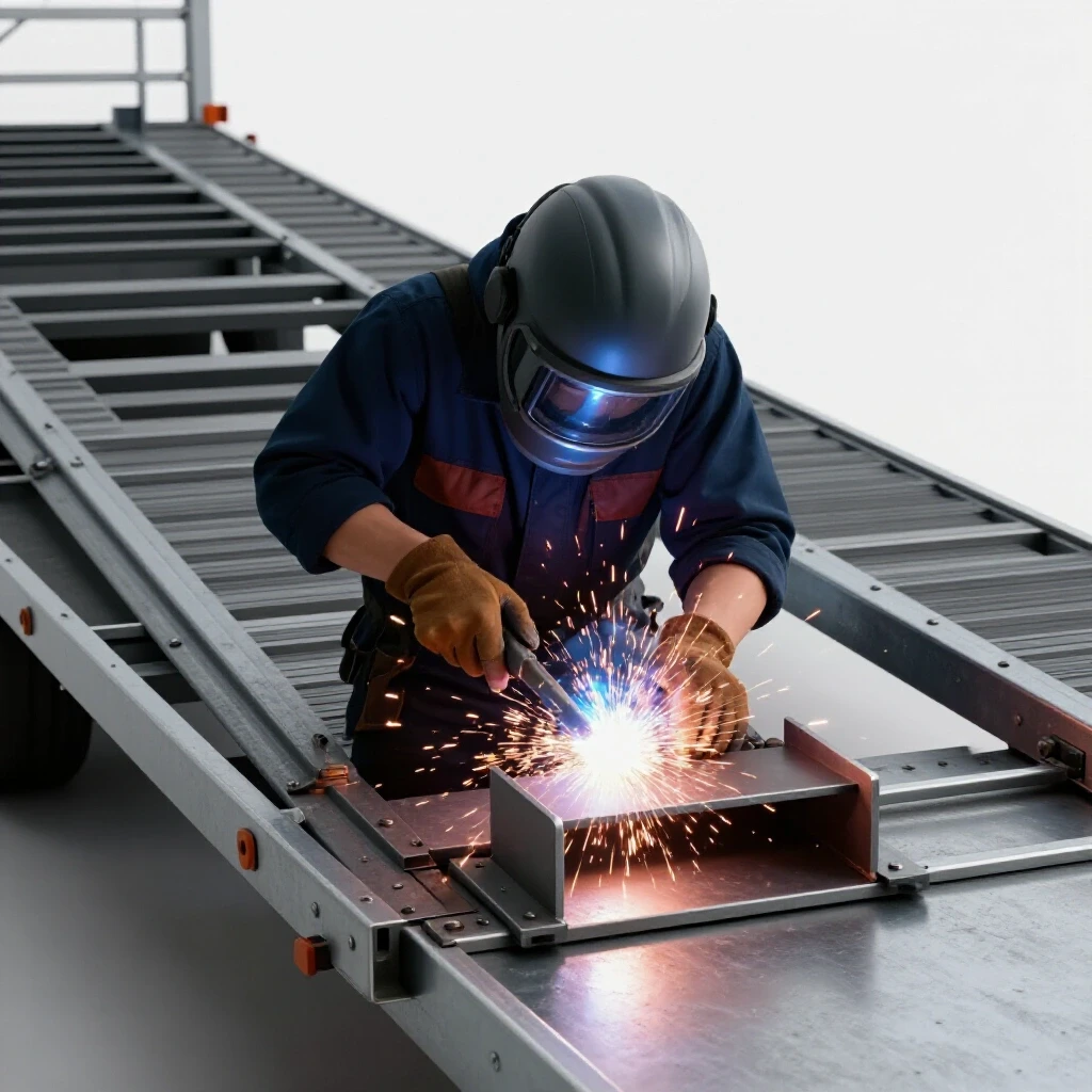
The heat from welding causes steel to expand and contract. If you weld one side of a gate frame completely before starting the other, the entire structure will pull out of square. This is similar to how we must carefully heat a seized cast-iron pulley to avoid cracking the hub. You must distribute the heat evenly across the entire assembly.
I use a “stitching” technique, where I place small welds in a staggered pattern. I might weld the top left corner, then move to the bottom right. This allows the metal to cool slightly between passes, minimizing the internal stresses that cause warping. A warped gate will never sit flat on the ground, making it dangerous to roll a heavy lathe across it.
Managing Heat Distortion in Long Spans
Long sections of steel tubing are particularly prone to bowing. To prevent this, I often clamp the tubing to a heavy welding table or a straight piece of I-beam during the welding process. This acts as a “heat sink” and a mechanical restraint, keeping the part true while the welds solidify.
- Backstepping: Weld in short sections, moving in the opposite direction of the overall weld path.
- Interpass Cooling: Allow the metal to become cool enough to touch (with gloves) before starting the next pass.
- Clamping: Use heavy C-clamps to keep the frame flat against your work surface.
Ensuring Full Penetration in Corner Joints
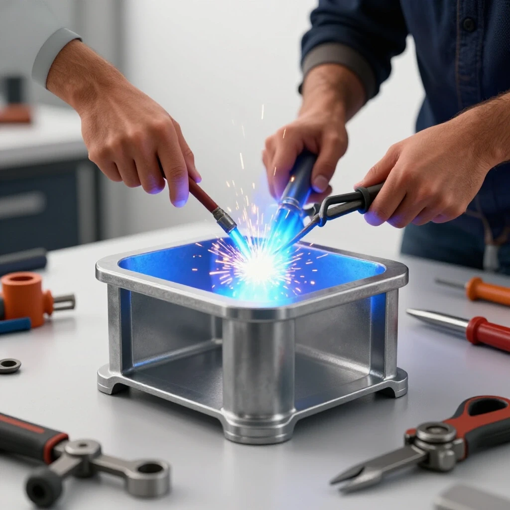
Corner joints are the most common failure points in loading gates. When two pieces of square tubing meet at a 90-degree angle, the weld must bridge the gap and fuse both walls. I always use a multi-pass technique on these corners: one root pass to join the metal and one or two “cover” passes to build up the thickness of the weld to match the tubing wall.
Reinforcing High-Stress Points and Hinges
The hinges and the points where the ramp contacts the trailer are under the most stress. When a 1,200-pound milling machine is halfway up the ramp, the leverage applied to the hinges is immense. We cannot rely on a single weld bead here. We must add reinforcement, often called “gussets” or “fish plates.”
A gusset is a triangular piece of steel plate welded into a corner to provide extra surface area for the load to distribute. Think of it as a brace for a machine stand. By adding a 1/4-inch thick gusset to every major corner, you significantly increase the gate’s resistance to twisting and bending.
Fabricating Heavy-Duty Hinge Brackets
Hinges for a heavy loading gate should be made from thick-walled pipe or dedicated weld-on barrel hinges. I prefer to fabricate my own using 1/2-inch steel pins and heavy-wall DOM (Drawn Over Mandrel) tubing. This ensures that the pivot point won’t shear off under the weight of the machine.
- Pin Selection: Use a Grade 5 or Grade 8 bolt or a cold-rolled steel pin.
- Sleeve Fit: The tubing should have a clearance of 0.010–0.020 inches over the pin to allow for grease and smooth movement.
- Weld Area: Wrap the weld entirely around the hinge sleeve to maximize the connection to the frame.
Using Fish Plates for Added Strength
If you must butt-weld two pieces of tubing together to reach a certain length, never leave the joint as a simple seam. I always “fish plate” these joints by welding a diamond-shaped piece of flat bar over the seam. This ensures that even if the primary weld fails, the plate will hold the structure together.
| Reinforcement Type | Material | Best Use Case |
|---|---|---|
| Corner Gusset | 1/4″ Plate Steel | Preventing frame racking/twisting |
| Fish Plate | 3/16″ Flat Bar | Strengthening butt-welded tubing joints |
| Hinge Backer | 3/8″ Plate Steel | Distributing hinge load across the frame |
| Cross Bracing | 1″ Square Tubing | Reducing bounce in the ramp center |
Safety Protocols and Fume Management
Welding produces intense ultraviolet light and hazardous fumes. As restorers, we are often working in enclosed garages or basements where ventilation is a challenge. Just as you wouldn’t use a lye-based electrolysis bath without proper safety gear, you must never weld without a plan for your lungs and eyes.
I use a dedicated fume extractor or a high-volume fan to pull smoke away from my face. This is particularly important when welding near old machinery that might have traces of lead paint or vintage lubricants nearby. The heat of the arc can vaporize these substances into a toxic cocktail.
Essential PPE for Structural Fabrication
- Auto-Darkening Helmet: Set to Shade 10 or 11 for structural MIG/Stick work.
- Respirator: A P100 rated mask designed for welding fumes.
- Leather Protection: A full-sleeve welding jacket and heavy-duty gloves to protect against sparks and UV burns.
- Fire Safety: Keep a dry-chemical fire extinguisher within reach and clear all sawdust or oily rags from the area.
Visual Inspection and Quality Control
Once the welds have cooled, I perform a thorough visual inspection. I look for “undercut,” which is a groove melted into the base metal next to the weld. This is a sign of too much heat and can weaken the joint. If I find any defects, I grind them out and re-weld the section. A structural weld should be uniform, slightly convex, and free of any visible holes or cracks.
Finishing and Rust Prevention
Once the fabrication is complete, the gate needs protection. We spend so much time removing machinery rust from our vintage finds; it would be a shame to let our new ramp succumb to the same fate. I start by grinding off any sharp edges or weld splatter that could cut a hand or snag a strap.
I then clean the entire structure with a wax and grease remover. For the coating, I prefer a high-zinc primer followed by a durable implement paint. This combination provides a tough, chip-resistant finish that can stand up to the abuse of heavy iron being dragged across it.
Applying a Durable Non-Slip Surface
A smooth steel ramp is a recipe for disaster when moving a top-heavy machine on a rainy day. I often mix a specialized non-slip additive (like fine sand or aluminum oxide) into the final coat of paint on the walking and rolling surfaces. This provides the traction needed to safely guide a machine up the incline.
- Prime: Apply two coats of zinc-rich primer.
- Paint: Use a heavy-duty enamel or epoxy-based paint.
- Traction: Sprinkle the non-slip media into the wet paint and apply a second coat over the top to “lock” it in.
Final Assembly and Testing
The final step is to mount the gate and perform a controlled test. I don’t start with my heaviest lathe. Instead, I use a known weight—perhaps a few bags of concrete or a smaller tool—and observe how the gate behaves. I look for any signs of bowing or popping sounds that might indicate a stressed weld.
When moving heavy gear, I always use a winch or a come-along to maintain control. The ramp gate is part of a system that includes the trailer, the straps, and the winch. By ensuring the gate is the strongest link in that chain, you can focus on the delicate task of navigating your latest machine rescue into its new home.
Actionable Checklist for Structural Welding Projects
- Verify Material: Ensure all steel is A36 mild or equivalent.
- Check Squareness: Keep tolerances within 1/16 inch across the frame.
- Bevel Joints: All structural joints must have a 30-45 degree bevel.
- Tack First: Secure the entire frame with tacks before final welding.
- Reinforce: Add gussets to all four corners and hinge points.
- Inspect: Use a magnifying glass and bright light to check for weld cracks.
- Protect: Apply a high-quality primer and non-slip topcoat.
Frequently Asked Questions
Can I use a 110V welder for building a heavy-duty loading gate? While some 110V MIG welders are rated for 3/16-inch steel, they are often operating at their absolute limit. For structural projects involving 2,000-pound loads, a 220V machine is highly recommended. It provides the “heat” necessary for deep penetration and a higher duty cycle, ensuring the machine doesn’t shut down mid-weld.
How do I know if my weld has deep enough penetration? A good sign of penetration is the “heat affect zone” (HAZ) visible on the back side of the steel. You should see a slight discoloration of the metal directly behind where you welded. If the back of the metal looks untouched, you likely didn’t get deep enough. This is why beveling the edges is so critical for structural integrity.
What is the best way to weld hinges to the frame? Hinges should be welded with multiple passes. Start with a root pass to join the hinge to the tubing, then add a “fillet” weld on either side to increase the contact area. Avoid welding the very ends of the hinge pins, as this can make the hinge brittle and prone to snapping.
Should I grind my welds flat for a better look? For structural loading gates, I recommend leaving the weld “proud” (raised). Grinding a weld flat can remove the throat thickness of the weld, potentially weakening the joint. Only grind the welds if they interfere with the fitment of another part, and even then, only remove the minimum amount of material.
How do I prevent the gate from warping during welding? The best method is to use a staggered welding sequence. Do not weld a long seam all at once. Instead, weld 2 inches, move to a different part of the gate, and weld 2 inches there. This keeps the heat localized and allows the rest of the frame to act as a brace.
Is it safe to use salvaged pipe for the frame? Only use salvaged pipe if you are certain it is structural grade steel and not thin-walled conduit or galvanized fence pipe. Galvanized steel releases toxic zinc fumes when welded, which can cause “metal fume fever.” If you must use it, you must grind off all the galvanizing at the weld site and wear a proper respirator.
How thick should the gussets be? As a general rule, gussets should be at least as thick as the material they are reinforcing. For a 3/16-inch wall tube frame, 1/4-inch plate gussets are ideal. They provide the extra “meat” needed to distribute the load without adding excessive weight to the gate.
What angle should the ramp be for moving machinery? For heavy, top-heavy tools, a shallower angle is always safer. Aim for a ramp that is at least twice as long as the height of the trailer bed. This reduces the effort required to winch the machine and lowers the center of gravity as the tool moves up the incline.
(This article was written by one of our staff writers, Richard Beaumont. Visit our Meet the Team page to learn more about the author and their expertise.)