How to Weld Highly Repeatable Structural Steel Frames (Fix)
Scaling a fabrication shop from a hobby space to a professional-grade operation is a journey of managing constraints. I have spent over 20 years in this environment, moving from a single welder in a cramped corner to a fully optimized workflow. The transition is rarely about buying a faster machine; it is about how you move material, manage power, and ensure every part that leaves your table is identical to the first one. When you move into high-volume frame assembly, the margin for error disappears. A quarter-inch of warp across ten frames can ruin a week of work and destroy your reputation.
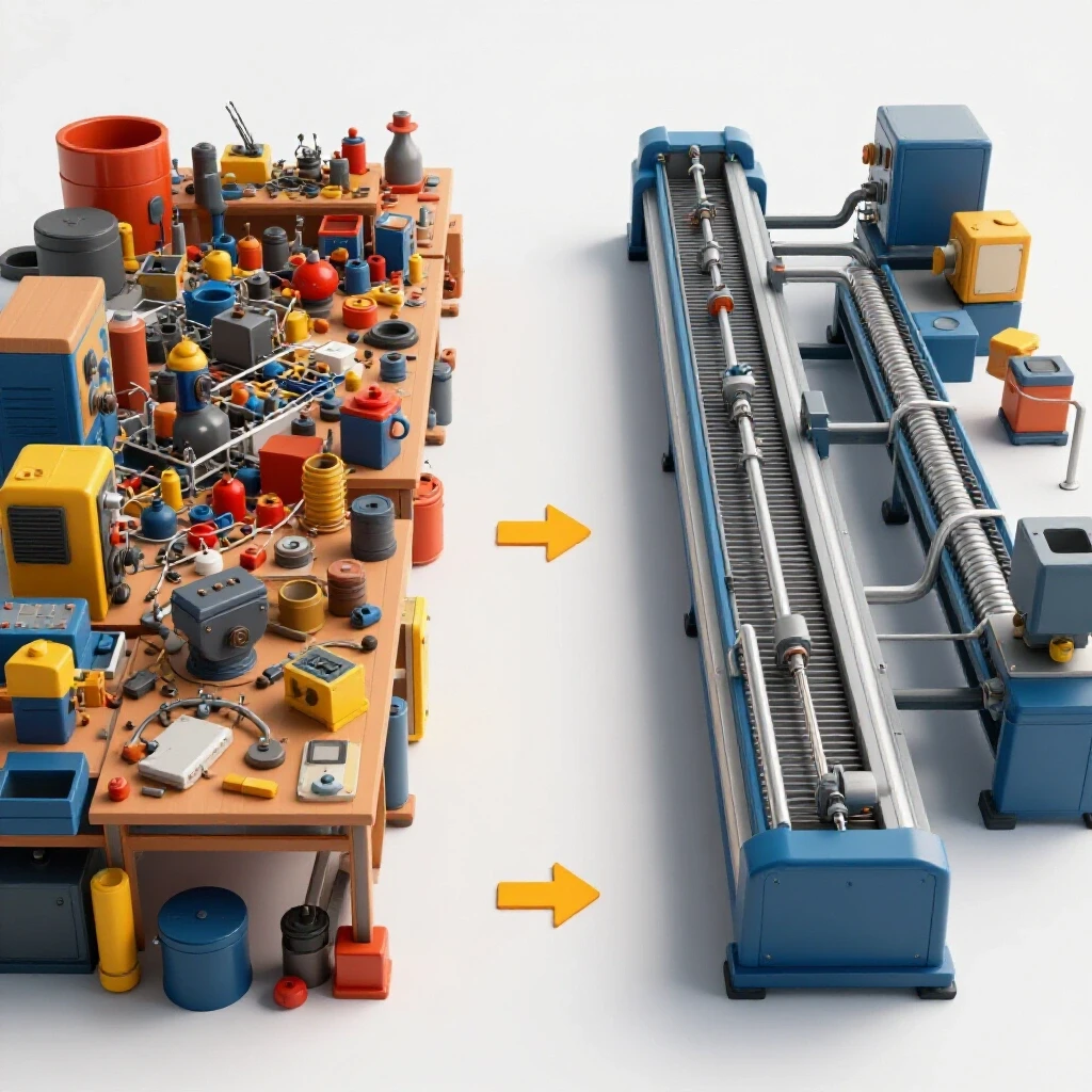
In my early years, I struggled with the physical toll of a poorly planned shop. I was constantly moving heavy steel tubes across the floor just to reach the saw, then moving them back to the welding table. It was a “spaghetti” workflow that wasted hours every week. Today, I focus on the industrial engineering of the space. We are looking at how to build a system where the shop works for you, rather than you working for the shop. This guide focuses on the technical and structural foundations required to produce consistent, high-quality mild steel assemblies in a semi-professional setting.
Mapping Workshop Layouts for Efficient Material Flow
A workshop layout is the strategic placement of equipment and material to minimize movement. It ensures a logical flow from raw stock to finished product, reducing physical strain and time waste. A well-mapped floor plan allows a fabricator to move through the assembly process without backtracking or clearing paths.
When I redesigned my current shop, I started with the “raw material to finished goods” path. For frames made of 2 x 2 inch mild steel tubing, the weight adds up quickly. You want your steel rack positioned near the entry door, followed immediately by the horizontal bandsaw or cold saw. This creates a “linear flow” where the material only moves in one direction. If you have to carry a 20-foot stick of tubing across the shop to cut it, you are losing money.
I recommend a minimum of 3 feet of clearance around all major workstations. This “access zone” is critical for safety and for maneuvering long workpieces. In my shop, I use a “U-shaped” flow for frame production. The material enters on the left, moves to the saw, then to the CNC plasma table for gussets and tabs, and finally to the central welding jig table. The finished frames exit through the main door on the right. This prevents “bottlenecks,” which are points in the process where work piles up because the next station isn’t ready or accessible.
| Layout Type | Movement Pattern | Best Use Case | Main Drawback |
|---|---|---|---|
| Linear Flow | Straight line from start to finish | Long, narrow shops | Requires a very long building |
| U-Shape | Entry and exit on the same side | Square or wide shops | Center can become cluttered |
| Cell Layout | All tools for one task in one “pod” | Complex, multi-part frames | Requires duplicate tools |
Powering the Shop with Stable 3-Phase Systems
3-phase power provides more consistent energy for industrial equipment by delivering three alternating currents that are out of phase with each other. This allows for smoother arcs in welding and higher efficiency in motors compared to standard single-phase residential power. For a scaling shop, stable power is the backbone of repeatability.
Most home-based shops start with 240V single-phase power. While this works for basic welding, professional-grade equipment often requires 3-phase power to run efficiently. If you are integrating a CNC plasma system or a high-output MIG welder, you will likely face the “phase gap.” To solve this without a massive utility bill, I use a Rotary Phase Converter (RPC). An RPC uses a 3-phase motor (the idler) to generate the third leg of power.
When setting up an RPC, balancing the voltage is the most critical step. You want the voltage between all three legs to be within 5% of each other. If the “manufactured” leg is too high or too low, it can overheat your welder’s transformer or cause your CNC electronics to glitch. I always suggest a digital phase converter if your budget allows. They are more expensive but provide a “cleaner” sine wave, which is vital for the sensitive control boards found in modern automation tools.
- Rotary Phase Converter: Best for heavy motor loads like saws and grinders.
- Digital Phase Converter: Best for sensitive electronics and CNC controllers.
- Static Converter: Generally avoided for high-output shops as they only provide two-thirds of the motor’s rated power.
Designing High-Volume Air Filtration and Fume Control
Fume management involves using high-volume fans and filters to remove harmful particulates from the breathing zone. A well-designed system keeps the air safe during long production runs and prevents fine dust from settling on sensitive electronics. In a shop where you are welding frames all day, air quality is a non-negotiable safety requirement.
I learned the hard way that a simple box fan in a window is not enough. For a dedicated welding station, you need a system that can move at least 1,000 to 2,000 Cubic Feet per Minute (CFM). The goal is to capture the fumes at the source before they rise into your face. I use a source-capture arm—a flexible duct that sits right over the weld area. This is connected to a central dust collector with a HEPA filter.
When designing your ductwork, “static pressure loss” is your biggest enemy. This is the resistance the air meets as it moves through the pipes. Every 90-degree bend and every foot of ribbed hose increases this resistance. I use smooth-walled galvanized pipe for my main runs and keep the total length as short as possible. For a standard 2-inch tubing frame project, a 6-inch main duct branching into 4-inch drops provides a good balance of air velocity and volume.
- Calculate the volume of your shop (Length x Width x Height).
- Aim for 6 to 8 air exchanges per hour for general shop air.
- Use source-capture hoods for 99% of welding fume removal.
- Check filter gauges weekly; a clogged filter can drop your CFM by half.
Precision Fixturing for Identical Frame Assembly
A jig is a custom-made tool that holds workpieces in the exact same position every time. It is the foundation of creating identical frames without the need for constant, manual measuring. In a production environment, the jig is what allows you to move from “building a frame” to “manufacturing a product.”
For mild steel frames, I prefer a modular welding table with a 16mm or 28mm hole pattern. These holes allow you to use “stops” and “clamps” to lock your tubing into place. When I am building a batch of 20 frames, I spend the first two hours perfectly squaring and locking down the jig. Once that jig is set, I can drop pre-cut 2 x 2 inch tubes into the slots, and I know the frame will be square to within a fraction of a degree.
If you don’t have a professional fixture table, you can build a “dedicated jig” out of angle iron or heavy plate. The key is to make the jig more rigid than the part you are welding. I often weld “stops” onto a thick steel plate to create a frame nest. This ensures that every piece of tubing sits in the exact same spot. Remember to leave “relief gaps” at the corners so you can weld the joints while the part is still in the jig.
- Use heavy-duty toggle clamps for fast loading and unloading.
- Incorporate “go/no-go” gauges to quickly check dimensions.
- Ensure the jig allows access to at least 75% of the weld joints.
- Always check the jig for “spatter build-up” which can throw off your measurements.
Managing Heat and Controlling Frame Distortion
Thermal distortion occurs when the heat from welding causes metal to expand and then contract as it cools, which pulls the assembly out of alignment. Controlling this requires a specific sequence of tacks and final welds to balance the internal stresses. Even with a perfect jig, heat can ruin a frame if not managed correctly.
The biggest mistake I see is “over-welding.” You don’t always need a continuous bead around every joint of a 2 x 2 inch frame. Often, structural integrity can be achieved with strategic stitch welds. When I start a frame, I use a “symmetrical tacking” sequence. I tack the top-left corner, then the bottom-right, then the top-right, and finally the bottom-left. This spreads the heat evenly across the structure.
I also use the “back-stepping” technique for longer welds. Instead of welding from left to right in one long pass, I weld in short segments from right to left, moving the start point of each segment further to the right. This helps cancel out the “pull” of the cooling metal. If a frame does warp, I use “flame straightening” or a cold-press to bring it back, but the goal is always to prevent the warp in the first place through proper sequencing.
| Distortion Factor | Impact on Frame | Mitigation Strategy |
|---|---|---|
| Longitudinal Shrinkage | Frame becomes shorter | Add 1/16″ to cut lengths |
| Angular Distortion | Corners pull out of square | Preset the angle or use rigid jigs |
| Transverse Shrinkage | Joints pull inward | Use proper gap spacing (1/16″) |
Integrating CNC Components into Manual Workflows
Integrating CNC tool workflows involves using computer-controlled machines, like a plasma table, to cut precise components that are then manually assembled. This bridge between automation and hand-crafting is where micro-manufacturers find their greatest efficiency. It removes the human error from the most complex parts of the build.
In my shop, the CNC plasma table is not for welding; it is for creating the “connectors.” For a structural steel frame, the CNC cuts the base plates, the gussets, and the mounting tabs. Because these parts are cut to within 0.010 inches of the design, they act as their own alignment tools. If I cut a gusset with a perfect 90-degree angle, it helps hold the 2 x 2 tubing in place during the tacking process.
The learning curve for CAD (Computer-Aided Design) and CAM (Computer-Aided Manufacturing) can be steep. I recommend starting with simple 2D parts. When you design your frames in software first, you can export a “cut list” that tells you exactly how many pieces of tubing you need. This reduces waste and ensures that your material-flow loop stays lean. The goal is to have all your “small parts” ready in a bin before you even turn on the welder.
- Design parts in CAD with “tab and slot” features for self-alignment.
- Use CAM software to optimize “nesting” to save material.
- Maintain the CNC gantry and rails weekly to ensure cutting accuracy.
- Calibrate the “torch height control” (THC) to prevent dross and bad cuts.
Financial Realities and System Commissioning
Transitioning to a semi-professional setup requires a clear understanding of capital amortization. This is the process of spreading the cost of an expensive tool, like a $15,000 CNC table or a $5,000 3-phase system, over its useful life. You need to know how many frames you must sell to pay for the upgrade.
When I bring a new system online, I follow a strict “commissioning” process. I don’t just turn it on and start a customer project. I run “test coupons” to verify the accuracy of the cuts and the strength of the welds. For a new jig, I will build three identical frames and measure them at 12 different points. If the variation is more than 1/32 of an inch, I go back and refine the jig.
It is also vital to track your “downtime.” In a high-output shop, if your air compressor fails, the whole shop stops. I keep a “critical spares” kit that includes plasma consumables, welder liners, and even a spare motor for my dust collector. Being professional means being prepared for the inevitable mechanical failures that come with scaling up.
- Track “Time per Frame” before and after every layout change.
- Calculate the “Return on Investment” (ROI) for every new tool.
- Perform monthly preventative maintenance on all 3-phase motors.
- Document your welding “recipes” (voltage, wire speed, gas flow) for repeatability.
Conclusion
Building a highly efficient shop for repeatable frame production is a marathon, not a sprint. It requires a shift in mindset from “how do I weld this?” to “how do I build a system that welds this?” By focusing on linear material flow, stable power, clean air, and rigid fixturing, you create an environment where quality becomes a baseline rather than a struggle.
My advice to any fabricator looking to scale is to start with the floor plan. No amount of expensive machinery can fix a shop that is physically disorganized. Once your flow is established, look at your power and air quality. These are the “invisible” foundations that allow you to work longer and more accurately. Finally, embrace the precision of jigs and CNC-cut components. When you stop measuring every part and start trusting your system, you have successfully moved from a hobbyist to a professional fabricator.
FAQ: Scaling Your Fabrication Operations
How much space do I really need for a professional frame-building setup? While you can build frames in a single-car garage, a professional-grade flow usually requires at least 800 to 1,000 square feet. This allows for dedicated zones for material storage, cutting, fixturing, and welding, while maintaining the necessary 3-foot safety buffers around equipment.
Can I run a CNC plasma table on a rotary phase converter? Yes, but it is not ideal. CNC electronics are sensitive to voltage fluctuations. If you use a rotary converter, ensure it is “CNC rated” or use a high-quality voltage regulator. A digital phase converter is a much safer choice for expensive automation tools.
What is the most common cause of frames pulling out of square? The most common cause is uneven heat distribution. If you weld one entire side of a joint before moving to the next, the cooling metal will pull the frame toward the weld. Using a symmetrical tacking sequence and a rigid jig is the best way to prevent this.
How often should I clean my shop’s air filtration filters? In a high-production shop, you should inspect filters weekly. Many systems have a “differential pressure gauge” that tells you when the filter is loaded. If you see a 20% drop in suction at your welding hood, it is time to clean or replace the filters.
Is it worth building a dedicated jig for a small run of 10 frames? Yes. If the frames need to be identical, a simple jig made of scrap angle iron will save you hours of measuring and “tweaking” later. The time spent building a jig is almost always recovered during the assembly phase.
What size ducting is best for a small shop dust collector? For most 1.5 to 3 horsepower dust collectors, a 6-inch main trunk line is the standard. This maintains enough air velocity (around 3,500 to 4,000 FPM) to keep heavy grinding dust and welding fumes moving without settling in the pipes.
Why should I use 2 x 2 inch tubing for my frames instead of larger sizes? This guide focuses on 2 x 2 inch and smaller because it is the “sweet spot” for many micro-manufacturing products like furniture, equipment stands, and light trailers. It is easy to handle manually but offers significant structural strength when welded correctly.
What is the first step in transition from a hobby shop to a semi-pro shop? The first step is a “workflow audit.” Draw your shop on paper and trace the path a piece of steel takes from the door to the finished product. If that line crosses itself or loops back, you have found your first bottleneck to fix.
Do I need 3-phase power for a standard MIG welder? Most modern inverter MIG welders run very well on 240V single-phase power. However, as you scale to larger machines or integrated CNC systems, 3-phase power becomes more efficient and provides a more stable arc for high-duty cycle production.
How do I prevent spatter from ruining my expensive welding fixture table? Use a high-quality, water-based anti-spatter spray on the table surface before welding. Also, ensure your welder is tuned correctly; excessive spatter is often a sign of incorrect voltage or wire speed settings for the gas you are using.
(This article was written by one of our staff writers, Edward Sinclair. Visit our Meet the Team page to learn more about the author and their expertise.)