How to Streamline Custom Fabrication Pipeline Layouts (Plan)
I still remember the night I stood in the middle of my garage, tripping over a tangled mess of welding leads and stepping around a pile of offcuts. I had just landed a contract for twenty custom gate frames, and my “hobby” setup was failing me. The problem wasn’t my skill with a TIG torch; it was the fact that I spent forty percent of my day just moving things out of the way. Over the last two decades, I have transitioned from that chaotic environment to a highly structured, semi-professional shop. I’ve learned that scaling a fabrication business isn’t just about buying faster tools—it is about how those tools interact with your floor space and your time.
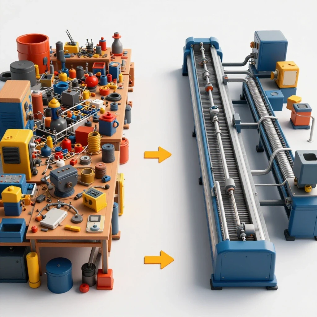
When you move from simple projects to high-output fabrication, the physical arrangement of your equipment becomes your most important tool. A poorly planned shop creates hidden costs in the form of operator fatigue, wasted movement, and safety hazards. My background in manufacturing operations taught me to look at a workshop not as a collection of tools, but as a single machine. Every step you take from the rack to the welding table is a “tax” on your productivity. To eliminate this tax, we have to look at the physics of material flow and the technical requirements of modern machinery.
Mapping the Physical Path of Production
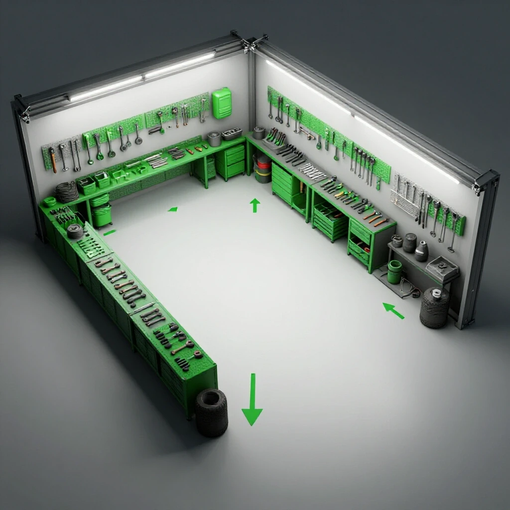
Effective shop planning begins with understanding how raw stock moves from the delivery truck to the shipping crate. By mapping these paths, you identify bottlenecks and eliminate wasted steps that drain your daily energy and profit margins. A logical flow ensures that heavy materials move the shortest distance possible.
In my early days, I had my horizontal bandsaw tucked in a corner because that is where the outlet was. This meant every twenty-foot stick of tubing had to be carried across the entire shop, rotated, and then fed into the saw. Now, I position my primary cutting station near the main door. The goal is to create a “U-shaped” or “linear” flow where material enters one side and exits the other as a finished product.
Identifying Workflow Zones
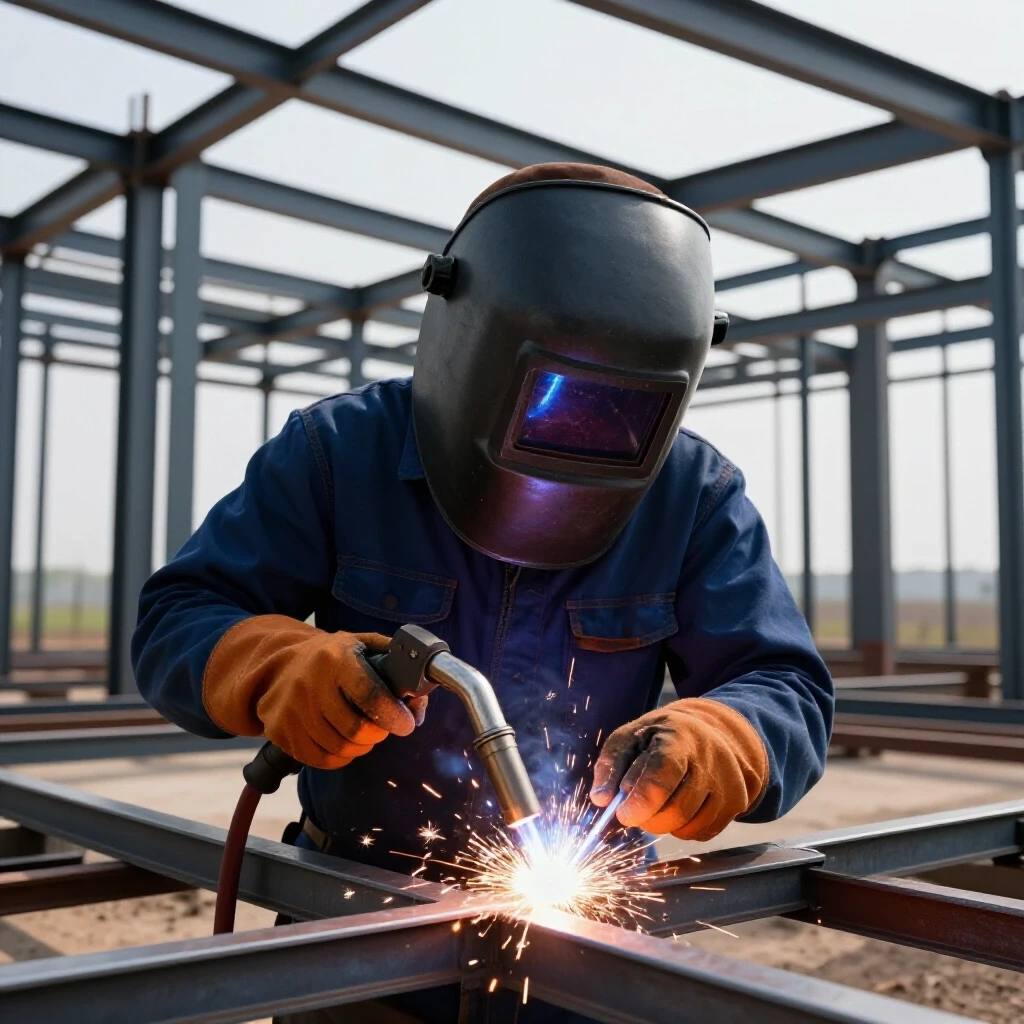
Zoning is the practice of grouping tools by their function and the mess they create. I divide my shop into “Hot,” “Cold,” and “Clean” zones. The Hot zone houses welding and plasma cutting, where sparks and fumes are prevalent. The Cold zone is for mechanical assembly and precision measurement. The Clean zone is where I keep my computer for CAD work and my finished inventory.
By separating these areas, you prevent grinding dust from ruining a fresh coat of paint or clogging the cooling fans on your expensive CNC electronics. I recommend a minimum of three feet for access zones around any major machine. This allows for safe movement and ensures you have enough room to perform maintenance without moving other equipment.
Workshop Layout Flow Comparison
| Feature | Batch/Chaotic Layout | Linear/Flow Layout |
|---|---|---|
| Material Travel | Long, crossing paths | Short, direct paths |
| Tool Accessibility | Cluttered, shared space | Dedicated work cells |
| Safety Risk | High (trip hazards) | Low (clear aisles) |
| Throughput | Inconsistent | Predictable and scalable |
| Cleanliness | Difficult to maintain | Zoned for easy cleanup |
Scaling Your Electrical Infrastructure for Heavy Machinery
Most residential or small commercial shops hit a wall with single-phase power when they begin adding industrial-grade tools. Transitioning to 3-phase systems through converters allows for more efficient motor operation and the use of professional-grade equipment without overloading your existing service panel.
When I upgraded to a larger mill and a high-capacity air compressor, I realized my standard 200-amp service wasn’t enough. 3-phase power is essentially three alternating currents that are out of phase with each other, providing more consistent torque for heavy motors. If you don’t have utility-provided 3-phase, you have to create it yourself.
Understanding Phase Converters
There are two primary ways to get 3-phase power in a small shop: Rotary Phase Converters (RPC) and Digital Phase Converters. An RPC uses a 3-phase motor (an idler) to generate the third leg of power. They are rugged and reliable but can be noisy and less efficient at low loads. Digital converters use solid-state electronics to create a very “clean” third leg, which is better for sensitive CNC electronics.
- Rotary Phase Converters: Best for manual lathes, saws, and grinders.
- Digital Phase Converters: Best for CNC plasma tables and mills.
- Variable Frequency Drives (VFDs): Excellent for single-machine 3-phase conversions where speed control is needed.
National Electrical Code (NEC) Frameworks for Small Shops
While I am not an electrician, I follow the NEC guidelines for wire sizing and circuit protection religiously. For a 3-phase converter setup, you must ensure your input breaker is sized to handle the total load of the converter plus the machines running off it. I use a “load balance log” to track how many amps each machine pulls during startup and under full load. This prevents the frustrating mid-project breaker trips that can ruin a CNC cut.
Designing High-Volume Air Management and Filtration
Clean air is a safety requirement and a machine longevity strategy. Designing a system with proper CFM and low static pressure ensures that metal dust and fumes are captured at the source before they settle on sensitive electronics. Metal dust is conductive; if it gets into your plasma controller, it can cause a short circuit that costs thousands to repair.
In my shop, I moved away from small, portable “shop vac” style collectors to a centralized cyclone system. A cyclone separator uses centrifugal force to drop heavy chips into a bin before the air reaches the fine filters. This keeps the filters clean longer and maintains a consistent airflow.
Calculating Airflow and Static Pressure
To design an effective duct network, you need to understand Cubic Feet per Minute (CFM) and static pressure. CFM is the volume of air moved, while static pressure is the resistance that air faces as it moves through pipes and elbows.
- Grinders/Sanders: Require 500–800 CFM for effective dust capture.
- CNC Plasma Tables: Often require 1,000–2,000 CFM depending on table size.
- Ducting: Use smooth-walled metal pipe rather than flexible ribbed hose to reduce static pressure loss.
Air Filtration Requirements by Tool
| Tool Type | Required CFM | Minimum Duct Diameter | Capture Method |
|---|---|---|---|
| Bench Grinder | 500 | 4 inches | Hooded shroud |
| CNC Plasma | 1,500 | 6–8 inches | Down-draft or Water table |
| Welding Station | 600 | 5 inches | Fume extraction arm |
| Sanding Station | 400 | 4 inches | Downdraft table |
Strategic Integration of CNC Plasma and Automation
Adding a CNC plasma table changes the rhythm of a shop more than any other tool. Success depends on gantry leveling, software proficiency, and creating a dedicated zone that doesn’t interfere with manual welding or assembly tasks. It turns you from a “maker” into a “process manager.”
My first CNC integration was a disaster because I didn’t account for the “splash zone.” Plasma cutting involves high-velocity air and molten metal. If your table is too close to your assembly bench, everything you build will be covered in fine grit. I eventually built a dedicated enclosure for the CNC area with its own ventilation and localized lighting.
Stepper vs. Servo Motors
When choosing or upgrading a CNC system, you will encounter stepper and servo motors. Stepper motors move in fixed increments and are generally more affordable, but they can “lose steps” if the gantry hits an obstruction. Servo motors use closed-loop feedback, meaning they always know exactly where they are. For high-output shops, servos offer higher speeds and better reliability, though they come with a higher technical learning curve.
Software and CAD/CAM Integration
The bottleneck in CNC work is rarely the machine; it is the software. I use a “staged” workflow for my files. I design in CAD (Computer-Aided Design), process the toolpaths in CAM (Computer-Aided Manufacturing), and then send the G-code to the machine controller.
- Standardize your templates: Save common material thicknesses and cut speeds in your CAM software.
- Nesting: Use nesting software to fit as many parts as possible on a single sheet of steel to reduce waste.
- Dry Runs: Always run a “ghost” cut without the torch firing to ensure the gantry doesn’t hit any clamps or table slats.
Measuring Layout Efficiency and Throughput
You cannot improve what you do not measure. Using simple metrics like “travel distance per part” or “setup time per job” helps justify the cost of reorganizing your floor space and upgrading your tools. I keep a simple spreadsheet that tracks my “torch-on time” versus my “handling time.”
When I first started tracking, I realized I was spending two hours of prep for every one hour of actual fabrication. By reorganizing my steel rack and installing a jib crane for heavy plate handling, I cut my prep time by fifty percent. This is the essence of lean manufacturing: identifying and removing “muda,” the Japanese word for waste.
Amortization and Capital Planning
Upgrading a shop is expensive. I look at equipment purchases through the lens of amortization—how long will it take for the tool to pay for itself? If a new CNC plasma table saves me ten hours of manual grinding a week, and my shop rate is $75 an hour, the machine pays for itself very quickly.
- Initial Cost: The price of the machine, shipping, and installation.
- Operating Cost: Electricity, consumables (nozzles/electrodes), and maintenance.
- Revenue Increase: The additional work you can take on because you are faster.
Workshop Layout Safety Checklist
- Aisle Width: Are all primary walkways at least 36 inches wide?
- Emergency Stops: Are E-stops for CNC equipment easily reachable?
- Lighting: Do you have at least 50 foot-candles of light at work surfaces?
- Ventilation: Is the air clear of visible smoke after five minutes of cutting?
- Trip Hazards: Are all cords and hoses dropped from the ceiling or covered?
Refining the Final Workflow
Transitioning to a professional-level shop is a marathon, not a sprint. Every time I finish a large project, I take thirty minutes to sit in my shop and think about what felt “clunky.” Did I have to walk too far for a specific wrench? Did the plasma smoke linger too long? These small observations drive the next set of layout improvements.
The most successful fabricators I know are the ones who treat their shop layout as a living document. They aren’t afraid to move a workbench or rewire a circuit if it means a smoother flow. By focusing on the physics of your space and the technical needs of your equipment, you move away from the stress of a cramped garage and into the efficiency of a true production facility.
Frequently Asked Questions
How much space do I really need for a CNC plasma table? While the table itself might be 4×4 or 5×10 feet, you need at least three feet of clearance on all sides for loading material and maintenance. Additionally, you need a nearby area for a computer workstation and space for a heavy-duty air compressor and refrigerated air dryer. Total dedicated space usually ends up being roughly double the footprint of the table.
Can I run a CNC table on a rotary phase converter? Yes, you can, but it is not always ideal. The “manufactured” leg of power from a rotary converter can have voltage fluctuations that sensitive CNC electronics dislike. If you use an RPC, ensure it is a “CNC grade” model with voltage stabilization, or use a digital phase converter for the most consistent power.
What is the best way to handle heavy steel plates alone? In a one-person shop, material handling is a major bottleneck. A gantry crane or a wall-mounted jib crane with an electric hoist is the gold standard. For those on a tighter budget, a heavy-duty hydraulic lift table or a modified engine hoist can save your back and allow you to load full sheets onto a CNC table safely.
How do I calculate the CFM needed for my dust collector? Start by looking at the port size on your most demanding tool. A 4-inch port generally needs about 400 CFM to maintain the “velocity” required to keep dust moving. However, you must also account for the length of your ducting and the number of bends. Each 90-degree elbow adds significant resistance, effectively lowering your CFM at the tool.
Is a water table or a downdraft table better for plasma cutting? Water tables are excellent for capturing dust and keeping the metal cool to prevent warping, but they can be messy and require chemical additives to prevent rust. Downdraft tables are cleaner for the operator but require a very high-volume fan (1,500+ CFM) and external venting or expensive filtration to be effective.
How often should I maintain my 3-phase converter? Rotary converters are low maintenance but should be checked every six months for loose electrical connections and bearing wear in the idler motor. Digital converters are solid-state and generally maintenance-free, though you should ensure their cooling fans are clear of metal dust.
What is “static pressure loss” in simple terms? Think of air moving through a pipe like water through a garden hose. If the hose is long or has kinks, the water comes out slower. In a shop, “kinks” are elbows, small-diameter pipes, and dirty filters. Static pressure loss is the measurement of how much “push” the air loses due to that friction.
Should I use PVC or metal for my air lines and dust ducts? For compressed air, never use PVC; it can shatter under pressure. Use copper, aluminum, or specialized plastic systems. For dust collection, metal ducting is preferred because it is fire-resistant and doesn’t build up static electricity, which can be a fire hazard with fine metal dust.
How do I balance my shop layout for both welding and CNC work? The key is separation. Keep your welding area (which produces UV light and heavy fumes) away from your CNC computer and electronics. Use welding curtains to block flashes and ensure your ventilation system pulls air away from the CNC gantry to prevent “grit” buildup on the precision rails.
What is the first step in redesigning a cramped shop? Clear the floor. You cannot see the potential of a space while it is covered in scrap. Once the floor is clear, use masking tape to “draw” the footprints of your machines on the ground. Walk the paths you would take during a typical project to see if the layout feels natural before you start bolting things down.
(This article was written by one of our staff writers, Edward Sinclair. Visit our Meet the Team page to learn more about the author and their expertise.)