Low Noise Exhaust Fans for Garage Welding Setups (DIY Plan)
I have spent the better part of 18 years in fabrication shops, often surrounded by the rhythmic hum of lathes and the sharp crackle of arc welding. In those years, I have learned that the most frustrating problems are not the ones that break a machine completely. The real headaches are the subtle issues—the vibration that ruins a finish, the intermittent electrical hum, or the smoke that lingers just long enough to sting your eyes. When I first started building my own shop systems, I realized that a poorly designed fume extraction setup could be just as much of a nuisance as a misaligned spindle.
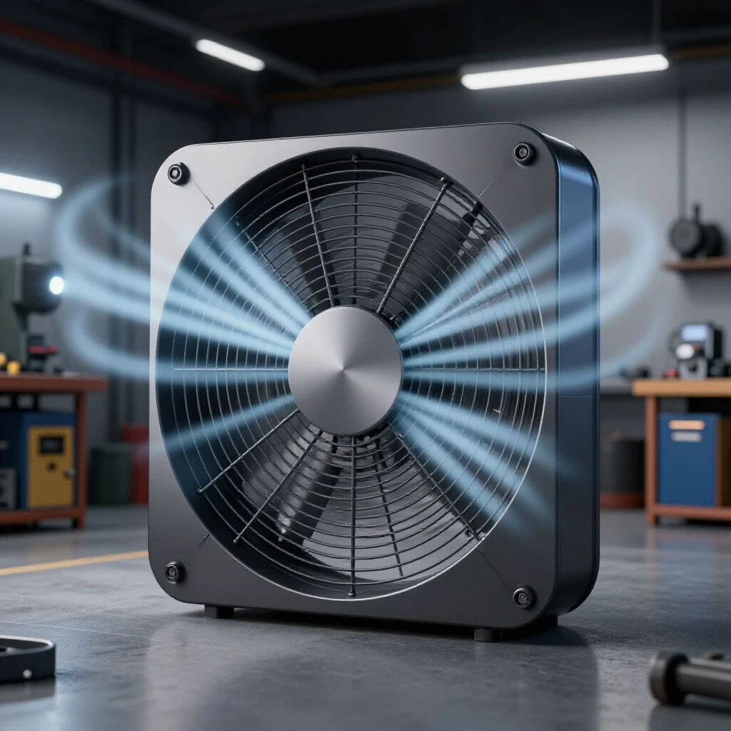
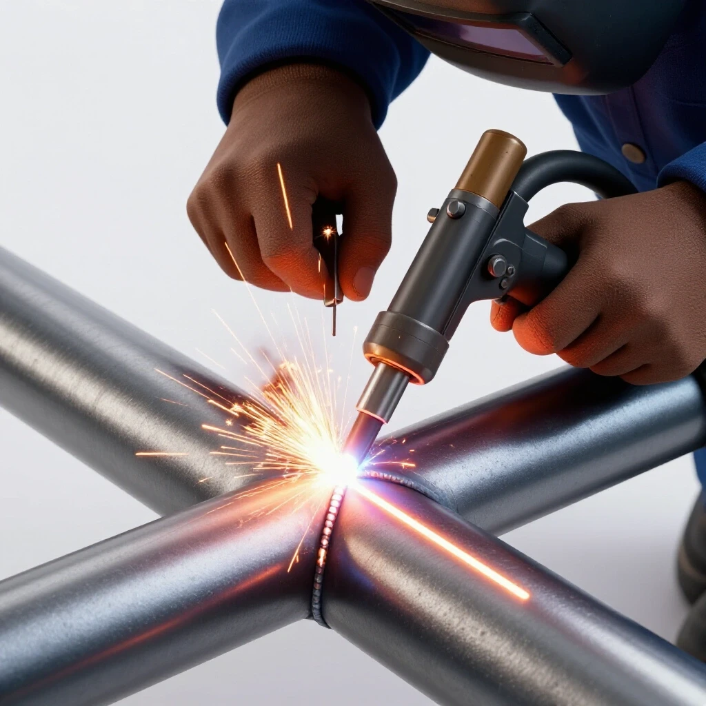
I remember working on a custom project where I was seeing consistent porosity in my TIG welds. I checked my gas, my tungsten, and my base metal. Everything seemed perfect. It took me two days to realize that my DIY ventilation fan was pulling air so aggressively and unevenly that it was creating a venturi effect, stripping the shielding gas right off the weld puddle. That experience taught me that every piece of equipment in a shop, even a shop-built exhaust system, must be diagnosed and tuned with the same precision as a CNC mill.
Mastering Systematic Diagnostics for Shop Airflow
Systematic diagnostics is the process of isolating a machine’s functions into mechanical, electrical, and environmental categories to find the root cause of a failure. Instead of replacing parts at random, you test specific variables to see how they affect the overall output of the system.
When you are building or troubleshooting a quiet air-moving system for a garage, you cannot just throw a bigger motor at the problem. You have to look at the fluid dynamics and the mechanical resonance of your housing. I start every diagnostic path by observing the system in its “failed” state. If a fan is too loud, is it a mechanical thumping, a high-pitched electrical whine, or the roar of turbulent air? By isolating these sounds, you can determine if you are dealing with a balance issue in the impeller or a restriction in your ductwork.
In my experience, many fabricators ignore the “baseline” of their equipment. Before you can fix a noise or vibration issue, you need to know what the motor sounds like without the fan attached. This is the first step in variable control. If the motor is quiet on its own but vibrates once the sheet metal housing is attached, you have a structural alignment or resonance problem, not a motor fault.
Eliminating Mechanical Resonance in Sheet Metal Housings
Mechanical resonance occurs when the vibration frequency of a moving part matches the natural frequency of the structure holding it, causing the metal to vibrate like a drum. In a DIY ventilation setup, this often manifests as a deep, low-frequency drone that can be felt through the walls of the garage.
To diagnose this, I use a method similar to checking for tool chatter on a lathe. Tool chatter is often caused by a lack of rigidity or an improper speed-to-feed ratio. In a fan housing, “chatter” happens when the sheet metal is too thin or lacks internal bracing. I prefer using at least 16-gauge cold-rolled steel for blower housings. If you use 22-gauge or thinner, the metal will oil-can and vibrate regardless of how well the motor is balanced.
Building on this, you can test for resonance by applying pressure to different parts of the housing while it is running. If the noise stops when you press your hand against a specific panel, you have found a vibration node. The fix is usually adding a stiffening rib or a layer of mass-loaded vinyl to change the resonant frequency of that panel.
Table 1: Vibration Source Identification
| Symptom | Potential Root Cause | Diagnostic Test |
|---|---|---|
| High-pitched whistling | Air leak or sharp edge in duct | Smoke test or soapy water on joints |
| Rhythmic thumping | Impeller imbalance or flat spot on belt | Visual inspection of blades for debris |
| Low-frequency humming | Motor mount vibration transfer | Isolate motor with rubber grommets |
| Metallic rattling | Loose fasteners or thin sheet metal | Physical pressure test on panels |
Troubleshooting Weld Porosity Caused by Extraction Airflow
Weld porosity is a defect where atmospheric gases become trapped in the molten weld pool, creating a honeycomb-like structure of holes that weakens the joint. While most fabricators blame contaminated filler rod or dirty base metal, the culprit is often the very fan meant to keep the air clean.
In a garage setup, if your intake is too close to the arc, it creates a high-velocity stream that can disturb your shielding gas. I’ve seen this happen most often with MIG and TIG processes where gas flow rates are typically set between 15 and 25 Cubic Feet per Hour (CFH). If your exhaust system is pulling air at a velocity that exceeds the “stiffness” of your gas envelope, you will get nitrogen contamination.
To diagnose this, I perform a “gas coverage test.” Set up your welding torch in a fixed position and run a bead with the fan off. Then, run the same bead with the fan on. If the second bead shows pinholes or a brown, sooty deposit, your airflow is too turbulent. The solution isn’t to turn the fan off, but to use a plenum or a larger intake hood to slow down the air velocity at the source while maintaining the overall volume of air being moved.
Correcting Alignment Faults in Custom Blower Assemblies
Mechanical alignment is the process of ensuring that the rotational axis of a motor is perfectly centered with the load it is driving. In a shop-built fan, even a tiny misalignment of 0.005 inches can lead to premature bearing failure and excessive noise that sounds like a grinding mill.
I use a digital dial indicator to check for “runout” on the motor shaft and the fan hub. Runout is the measure of how much a rotating object wobbles as it spins. For a quiet, long-lasting setup, you should aim for a total indicated runout (TIR) of less than 0.002 inches. If you find the hub is wobbling more than that, it will create a centrifugal force that shakes the entire mounting bracket.
Interestingly, many people think they have a “bad motor” when they actually have a “bad fit.” If the bore of your fan impeller is slightly larger than the motor shaft, the set screw will push the impeller off-center. This creates a heavy side that vibrates at high RPM. I always recommend using a keyed shaft and a precision-machined hub rather than a simple friction fit to ensure the center of mass stays where it belongs.
Metalworking Diagnostic Guide: Alignment Checklist
- Check Shaft Straightness: Use a dial indicator on the motor shaft while rotating it by hand.
- Verify Hub Fit: Ensure the impeller slides onto the shaft with a “snug” fit; there should be no perceptible wiggle before tightening the set screw.
- Measure Axial Play: Pull and push on the shaft to check for excessive bearing movement.
- Inspect Mounting Plane: Use a precision level to ensure the motor base is perfectly flat; a twisted base can warp the motor housing and cause internal friction.
- Dynamic Balance Test: If vibration persists, add small weights (like adhesive wheel weights) to the impeller blades one at a time to see if the vibration decreases.
Designing Sound-Dampened Enclosures for Quiet Operation
A sound-dampened enclosure is a secondary structure built around a noisy component to trap and dissipate acoustic energy. For a garage welding setup, this means building a box, usually out of sheet metal or plywood, lined with specialized materials to kill the noise of the motor and the air rushing through the blades.
The science here is about “impedance mismatch.” When sound waves hit a material that is significantly denser or more porous than air, they lose energy. I’ve found that a “sandwich” construction works best: a rigid outer shell (sheet metal), a layer of high-density acoustic foam or rock wool, and an inner perforated metal liner. The perforated liner allows the sound waves to enter the insulation rather than bouncing back into the fan.
One mistake I see often is forgetting about the “flanking paths.” Sound is like water; it will find the easiest way out. If you build a beautiful insulated box but have a 1-inch gap where the ducting exits, the noise will leak out of that gap and negate your hard work. Using flexible rubber couplings between the fan and the hard ducting is a critical step. These couplings act as a “vibration break,” preventing the fan’s mechanical energy from traveling down the metal pipes and turning your entire duct system into a giant speaker.
Electrical Diagnostic Steps for Fabrication Ventilation Motors
When dealing with shop motors, electrical troubleshooting often involves checking for resistance, voltage drops, and proper grounding. Most garage fans use single-phase AC motors or, more recently, high-efficiency DC motors. A motor that “hums” but won’t start is usually suffering from a bad start capacitor or high internal resistance.
I always start by measuring the resistance (Ohms) across the motor windings. If you see “OL” (open loop) on your multimeter, the internal wire has snapped or burned out. If the resistance is very low, say less than 1 Ohm on a small motor, you might have a short circuit. Another common issue in garage shops is “voltage drop.” If you are running your fan on the same circuit as your welder, the fan might struggle to stay at its rated RPM when you strike an arc, leading to overheating.
Table 2: Motor Electrical Benchmarks
| Component | Expected Reading | Indication of Failure |
|---|---|---|
| Main Windings | 2 to 20 Ohms (varies by HP) | 0 Ohms (short) or Infinite (open) |
| Start Capacitor | Rated Microfarads (µF) ±10% | Bulging casing or 0 µF reading |
| Ground Path | Less than 0.5 Ohms | High resistance indicates poor safety ground |
| Voltage at Load | 115V to 125V (for 120V motor) | Less than 108V suggests undersized wiring |
As a result of these electrical checks, you can avoid the “electrical gremlins” that cause intermittent shutdowns. I once spent a whole afternoon trying to figure out why a fan was losing power, only to find that the vibration had loosened a wire nut inside the junction box. Now, I always use vibration-resistant crimp connectors in any motor housing.
Managing Airflow Harmonics and Ducting Layouts
The way you run your ductwork in a garage has a massive impact on both noise and efficiency. Just like a fluid system in a hydraulic press, air does not like to turn sharp corners. Every 90-degree elbow you add to your system creates turbulence, which increases noise and decreases the “static pressure” your fan can overcome.
In the world of diagnostics, we call this “system effect.” If you place an elbow directly at the outlet of your fan, the air hasn’t had time to stabilize, and it will crash into the wall of the pipe. This creates a resonant “wooshing” sound. I follow the “three-diameter rule”: try to have a straight run of pipe at least three times the diameter of the duct before and after any fan or elbow.
If you are struggling with a “noisy” pipe, look for “oil-canning.” This is when the flat sides of a rectangular duct flex in and out due to pressure changes. Switching to round spiral ducting or adding cross-breaking (creasing the metal in an X pattern) to flat panels can significantly increase rigidity and kill that drumming noise.
Practical Steps for a Systematic DIY Build
When you are ready to execute a repair or a new build, follow a structured sequence. This prevents you from having to take everything apart because you forgot a single internal seal or fastener.
- Component Testing: Bench-test your motor and impeller before they ever touch the housing. Verify they spin true and quiet.
- Housing Fabrication: Use heavy-gauge metal and incorporate stiffening bends. Ensure all seams are airtight using high-temp silicone or specialized foil tape.
- Vibration Isolation: Mount the motor on rubber isolators. Never bolt a motor directly to a large sheet metal panel without a gasket.
- Acoustic Lining: Install your insulation. If using rock wool, ensure it is encapsulated so fibers don’t get pulled into the airflow and your lungs.
- Final Alignment: Once the system is assembled, use your dial indicator one last time to ensure the weight of the impeller hasn’t sagged the motor shaft.
- Performance Logging: Record the initial noise level (using a smartphone decibel app) and the airflow speed. This gives you a “healthy” baseline for future troubleshooting.
Case Study: The “Ghost” Vibration in a Custom Plenum
A few years ago, a fellow fabricator asked me to look at his shop-built extraction unit. It was a well-built sheet metal box, but it produced a bone-jarring rattle every time it hit full speed. He had already replaced the bearings and balanced the fan.
I approached it like a machining chatter problem. I started by checking the “rigidity” of the setup. We found that the mounting bracket for the motor was made of 1/8-inch flat bar, which was just flexible enough to act like a tuning fork. At 1,750 RPM, the motor’s natural vibration frequency matched the “spring rate” of that flat bar.
We didn’t need a new motor. We simply welded a piece of angle iron across the bracket to stiffen it. By increasing the rigidity, we moved the resonant frequency of the bracket far above the motor’s operating range. The rattle vanished instantly. This is why I tell people: diagnostics is about finding the “why,” not just the “what.”
Conclusion: Developing Your Diagnostic Intuition
Developing a systematic approach to shop issues takes time and patience. Whether you are chasing a ghost in your electrical panel or trying to quiet down a roaring exhaust fan, the methodology remains the same: isolate, test, and verify. Don’t be discouraged by dead ends. Every time a test fails to find the problem, you have successfully eliminated a variable, bringing you one step closer to the truth.
In the garage, where we often work alone, our tools and our environment need to support our focus, not distract from it. A quiet, efficient shop isn’t a luxury; it’s a sign of a fabricator who understands their craft. By applying these mechanical and electrical diagnostic steps, you can ensure your setup runs as smoothly as a well-oiled machine, allowing you to focus on the quality of your welds rather than the noise in your ears.
FAQ: Troubleshooting Quiet Extraction Systems
Why does my DIY fan get louder when I attach the ducting? This is usually due to “static pressure” and turbulence. When the fan has to push air through a pipe, the resistance increases. If the ducting is too small or has sharp bends, the air becomes turbulent, creating a “rushing” or “roaring” sound. Ensure your duct diameter matches the fan’s outlet and use long-sweep elbows.
Can I use a dimmer switch to slow down my fan motor and reduce noise? Generally, no. Most standard AC shop motors are induction motors and require a specific frequency to run. Using a standard light dimmer can starve the motor of voltage, causing it to overheat and hum loudly. For speed control, you need a Variable Frequency Drive (VFD) for three-phase motors or a specific speed controller designed for PSC (Permanent Split Capacitor) motors.
How do I know if my vibration is coming from the motor or the fan blades? Remove the fan blades/impeller and run the motor by itself. If the vibration is gone, the issue is the balance or alignment of the fan blades. If the vibration persists, the motor has internal issues like worn bearings or a bent shaft.
What is the best material for dampening sheet metal noise? Mass-loaded vinyl (MLV) is excellent because it adds weight without much thickness, which stops the metal from vibrating. For absorbing the sound of rushing air, open-cell acoustic foam or mineral wool (rock wool) is more effective.
Is it normal for my motor to get hot during long welding sessions? Motors are rated for specific temperature rises, often marked as “Class F” or “Class B” on the nameplate. However, if it’s too hot to touch (above 140°F), it may be overloaded, have poor airflow for cooling, or be suffering from a voltage drop in your shop’s wiring.
How can I test for air leaks in my DIY housing without expensive tools? A simple “smoke pencil” or even a stick of incense can show you where air is being sucked in or blown out. Run the fan and move the smoke source along the seams. If the smoke is violently pulled in or pushed away, you have a leak that needs sealing.
Will a quiet exhaust system affect my TIG weld quality? Only if the intake velocity is too high at the weld site. If you see porosity, try moving the intake hood further away or using a “flaring” nozzle to spread the suction over a larger area, which reduces the “wind” felt at the arc.
What should I do if my fan makes a high-pitched whistling sound? Whistling is almost always caused by air moving over a sharp edge or through a small gap. Check the internal seams of your housing and the edges of your fan blades for burrs or misaligned joints. Smoothing these out with a file or some sealant usually solves the problem.
How often should I check the alignment of my DIY setup? In a hobby or small-scale shop, an annual check-up is plenty. However, if you notice a change in the “sound” of the machine or see increased vibration, perform an alignment check immediately to prevent bearing damage.
Does the length of my exhaust pipe matter for noise? Yes. Longer pipes create more resistance, which can make the fan work harder and louder. Additionally, very long runs of thin-walled pipe can act like a resonator. Keeping runs short and straight is always the best practice for both noise and efficiency.
(This article was written by one of our staff writers, Paul Whitaker. Visit our Meet the Team page to learn more about the author and their expertise.)