Simple Workshop Layout Changes That Save Planning Time (Tips)
I have spent nearly two decades in the hum of industrial shops, tearing down lathes and rebuilding milling machines. Over those 17 years, I have learned that a workshop is more than just a collection of heavy iron. It is a living system where the physical placement of your equipment dictates how much time you spend thinking about a project versus actually doing it. When I first started, I thought a bigger motor or a shiny brand name was the key to productivity. I was wrong. The real efficiency comes from how you organize your workspace to reduce the mental load of mapping out your next move.
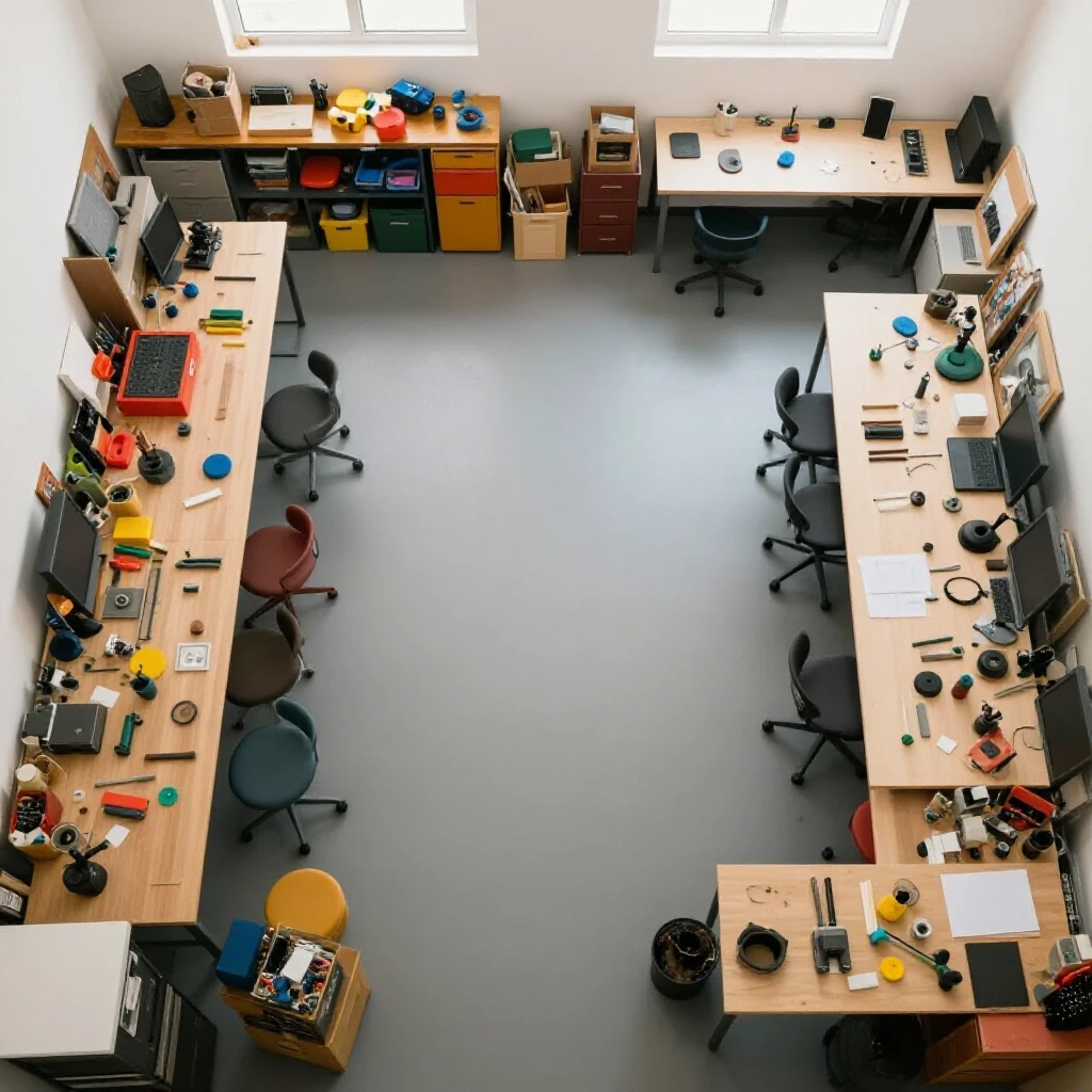
Many fabricators get caught in “spec-sheet paralysis.” They spend weeks comparing the horsepower of two different lathes but forget to consider where that lathe will sit in relation to their stock rack. If you have to walk twenty feet and move a heavy cart every time you need a piece of round bar, your planning time doubles. In my shop, I have seen how small shifts in tool positioning can eliminate the friction that causes project delays. We are going to look at how to evaluate machinery from the ground up and how to arrange those tools to keep your workflow moving without constant pauses for reorganization.
Prioritizing Frame Rigidity and Material Quality for Better Floor Placement
Frame rigidity refers to a machine’s ability to resist bending or vibrating under a heavy workload. Choosing tools with high-quality cast iron frames allows for more flexible placement because these machines do not rely on a perfectly level, thick concrete pad to maintain their internal alignment as much as lighter, sheet-metal tools do.
When I evaluate a new piece of equipment, I look at the “bones” first. Most entry-level machines use thin-walled steel tubing or light aluminum castings. These materials are prone to harmonic resonance—that high-pitched squeal you hear when a cut goes wrong. In contrast, heavy gray cast iron (often labeled as Class 25 or Class 30) acts like a sponge for vibration. This dampening effect is critical because it means you can place the machine near other tools without the vibration traveling through the floor and ruining a finish on a nearby grinder.
I once worked on a project where we had a light-duty mill and a precision lathe on the same long workbench. Every time the mill took a heavy pass, the lathe finish suffered. We didn’t need a new lathe; we needed a machine with a heavier base that could stay “dead” while other work happened around it. If you choose machines with high structural mass, you save time in the planning phase because you don’t have to worry about isolating each tool from its neighbor.
| Cast Iron Grade | Tensile Strength (PSI) | Best Use Case | Vibration Dampening |
|---|---|---|---|
| Class 25 Gray Iron | 25,000 | Small lathe beds, drill press tables | High |
| Class 30 Gray Iron | 30,000 | Milling machine columns, industrial lathes | Excellent |
| Ductile Iron | 60,000+ | High-impact parts, gears, levers | Moderate |
| Sheet Steel | N/A | Tool stands, light-duty enclosures | Low (Noisy) |
Why Heavy Castings Dampen Harmonics
Gray iron contains graphite flakes that break up the path of mechanical vibrations. When a cutting tool hits a hard spot in a workpiece, the energy has to go somewhere. In a light machine, it bounces around the frame, causing “chatter.” In a heavy casting, that energy is converted into a tiny amount of heat within the metal itself. This means you can push your tools harder and spend less time adjusting your feed rates during the planning stage.
- Look for “webbing” or internal ribbing inside the castings.
- Check the weight specs; a heavier machine is usually a more stable machine.
- Avoid machines that use sand-filled hollow tubes to “fake” their weight.
Assessing Motor Designs to Optimize Power Access and Workflow
Motor design determines how a machine draws power and how much heat it generates during use. By selecting the right motor technology, you can group tools more effectively based on your shop’s electrical capacity, reducing the time spent figuring out which breakers can handle a multi-tool project sequence.
In my experience, the debate usually sits between traditional induction motors and modern brushless DC (BLDC) motors. Induction motors are the workhorses of the industry. They are simple and reliable, but they are heavy and can draw a massive “inrush” of current when they start up. If you have three induction-motor tools on one circuit, you can’t run them at the same time. This forces you to plan your project around your power grid rather than your workflow.
Brushless motors and machines equipped with Variable Frequency Drives (VFDs) are much smarter. They ramp up speed slowly, which prevents those annoying breaker trips. When I redesigned my secondary shop, I switched to VFD-controlled motors. This allowed me to place my most-used tools closer together because I knew I wouldn’t blow a fuse if the air compressor kicked on while I was using the lathe.
Comparing Inverter vs. Transformer Efficiency
Efficiency isn’t just about your electric bill; it is about heat. Transformer-based welders, for example, get very hot and require large cooling fans. These fans blow dust everywhere, which means you have to plan your layout to keep your precision tools far away from your welding station. Inverter-based machines run cooler and cleaner, allowing for a tighter, more efficient shop footprint.
- Induction Motors: Best for constant-speed tasks like drill presses.
- BLDC Motors: Excellent for variable speed without losing torque, ideal for small lathes.
- VFD Drives: The gold standard for converting 3-phase industrial motors to run on home 1-phase power.
Measuring Spindle Runout to Define Precision Work Zones
Spindle runout is the amount of “wobble” in a rotating shaft, measured in thousandths of an inch. By verifying the accuracy of your machines, you can designate specific areas of your shop for high-precision tasks, which simplifies the decision-making process when you start a new build.
If you are researching a new lathe or mill, the Total Indicated Runout (TIR) is the most important number you will see. A machine with a TIR of 0.0005 inches is a precision instrument. A machine with 0.005 inches is a “roughing” tool. I always keep a dial indicator handy to test every new tool that enters my shop. I have found that marketing brochures often lie, but a plunger-style indicator on the spindle nose tells the truth.
Knowing which of your tools are the most accurate allows you to organize your shop into “zones.” I keep my highest-precision lathe in the cleanest corner, far from the grinding dust. This layout change means I don’t have to spend time cleaning and recalibrating the machine every time I need to make a press-fit part. I know that zone is ready for “tenth-level” work (work measured in ten-thousandths of an inch).
| Tool Type | Acceptable TIR (Inches) | Precision Level |
|---|---|---|
| Toolroom Lathe | 0.0001 – 0.0003 | Ultra-Precision |
| Standard Bench Lathe | 0.0005 – 0.0010 | High Precision |
| Jobber Drill Press | 0.0030 – 0.0050 | General Utility |
| Handheld Grinder | 0.0100+ | Rough Work |
How to Perform a Spindle Runout Test
To test a spindle, you need a magnetic base and a dial test indicator. Clean the internal taper of the spindle thoroughly. Any bit of dust will throw off your reading. Place the indicator tip against the inner surface of the taper and rotate the spindle by hand. The “sweep” of the needle shows you the runout. If the needle jumps more than 0.001 inches on a lathe you just bought, it might need a bearing adjustment or a return to the factory.
- Clean all surfaces with a lint-free cloth.
- Mount the magnetic base on a solid part of the machine frame.
- Slowly rotate the spindle 360 degrees.
- Note the high and low points on the dial.
Inspecting Slide Tolerances for Ergonomic Station Placement
Slide tolerances involve the “play” or “backlash” in the moving parts of a machine, such as a mill table or a lathe carriage. Understanding these tolerances helps you position tools so that the most frequent manual adjustments are within easy reach, minimizing the time spent moving around the machine to check your work.
I have spent many hours “scraping in” ways on old machines to get them back to factory specs. The “ways” are the tracks that the machine parts slide on. If these are too loose, the tool will dive into the work. If they are too tight, you will wear yourself out trying to turn the handwheels. When you are choosing a tool, look for “dovetail” or “box” ways. Dovetail ways are great for smaller machines because they are easy to adjust using a metal strip called a “gib.”
By knowing how much backlash is in your lead screws (the threaded rods that move the slides), you can decide where to place your Digital Readouts (DROs). A DRO is a screen that tells you exactly where the tool is. If a machine has a lot of backlash, putting a DRO on it is a layout change that saves massive amounts of planning time because you no longer have to “count turns” of the handwheel and account for the mechanical slop.
Why Way Design Impacts Tool Longevity
The shape of the sliding surfaces dictates how well the machine holds oil. V-ways, common on lathes, help center the carriage automatically. Flat ways are more robust for heavy weights. If you are planning a shop for heavy repair work, you want flat or box ways. For high-speed, light-duty prototyping, dovetail ways are often more than enough.
- Dovetail Ways: Common on hobby mills; adjustable and compact.
- Box Ways: Found on heavy industrial machines; best for heavy cuts.
- Linear Rails: Found on modern CNCs; very fast but sensitive to dust.
Evaluating Speed Controllers and Electrical Efficiency for Tool Grouping
Speed controllers, such as VFDs or DC motor drivers, manage how fast a tool spins. Selecting machines with efficient, reliable controllers allows you to group power-hungry equipment together without overloading your shop’s electrical infrastructure, which keeps your project momentum high.
One of the biggest mistakes I see is people buying “budget” variable speed machines that use cheap pulse-width modulation (PWM) boards. These boards are notorious for failing under load. I have a drawer full of fried circuit boards from entry-level lathes that couldn’t handle a heavy cut at low RPM. When the board dies, your project stops. You spend hours researching parts instead of making chips.
A better choice is a machine with a brushless motor or a high-quality VFD. These systems provide “constant torque,” meaning the motor doesn’t bog down when you slow it down. From a shop layout perspective, these machines are quieter. This allows you to place them in areas where you might need to hear a phone or a radio, rather than tucking them away in a noisy “hot zone.”
Standardizing Your Electrical Footprint
If you can, try to standardize your tools to use the same type of power. I try to keep my heavy-duty tools on 220V circuits. This reduces the amperage draw compared to 110V, which means my wires stay cooler and my motors run more efficiently. When your electrical setup is consistent, you can move tools around your shop more easily as your needs change.
- Check the “Duty Cycle” of your motor controllers.
- Look for “Thermal Overload Protection” on the spec sheet.
- Ensure the controller is housed in a dust-proof enclosure.
Planning Spare Parts and Consumable Access Near the Machine
Spare parts and consumables are the items that wear out, like inserts, belts, and bearings. Organizing these items directly at the tool station is a simple physical change that eliminates the need to stop and search for replacements mid-project.
In my maintenance career, the most productive shops weren’t the ones with the most expensive tools; they were the ones where the mechanic didn’t have to walk across the building for a wrench. I recommend building “point-of-use” storage. If your lathe uses 1/2-inch shank tools, those tools and the hex keys to change them should be within arm’s reach of the headstock.
I use a simple “shadow board” or a dedicated drawer for every major machine. If I see an empty spot on the board, I know I’m low on a specific insert or drill bit. This visual feedback loop saves me from starting a project only to realize halfway through that I don’t have the cutting tool I need. It is a layout strategy that focuses on visibility and reach.
Creating a Maintenance Tracking Framework
I keep a small notebook or a laminated card attached to every machine. I record when I oiled the ways, when I changed the gear oil, and the part numbers for the drive belts. This removes the “guessing game” from tool maintenance.
- Keep a “First-Aid Kit” for each machine (spare fuses, common belts, shear pins).
- Label your drawers clearly with the specific tool size.
- Store heavy tooling (like large lathe chucks) on a rolling cart at the same height as the machine spindle to save your back.
A Checklist for Inspecting New Workshop Machinery
Before you bolt a new tool to your floor, you need to verify its mechanical integrity. This checklist ensures that the machine you bought matches the marketing hype and is ready to be integrated into your shop layout.
- Check for Shipping Damage: Inspect the crate for punctures. Even a small bump can bend a lead screw or crack a cast iron foot.
- Clean the Cosmoline: Most machines ship with a thick, sticky grease. Use a degreaser to remove it all before moving any slides. Moving a slide over dirty cosmoline can score the ways.
- Verify Level: Use a precision machinist’s level (not a carpenter’s level). A machine that isn’t level will twist over time, ruining its accuracy.
- Test the Spindle: Run the spindle at low RPM for 20 minutes. Feel the bearings. They should be warm, not hot. If they are hot to the touch, the preload might be too tight.
- Measure Backlash: Use a dial indicator to see how much the handwheel moves before the table actually starts to travel. Anything under 0.005 inches on a new manual machine is generally acceptable.
- Inspect the Wiring: Open the electrical cabinet. Look for loose terminals or “bird’s nest” wiring. Tighten any screws that might have vibrated loose during shipping.
Conclusion: Building a Shop That Works With You
Success in the workshop isn’t about having a “perfect” setup from day one. It is about making small, data-driven adjustments to how your tools are positioned and maintained. By focusing on the structural quality of your machinery—like the grade of the cast iron and the precision of the spindle—you create a foundation that allows for a more flexible and efficient workspace.
When you reduce the physical distance between your stock, your tools, and your consumables, you naturally reduce the time it takes to plan and execute a project. You stop fighting your environment and start focusing on the craft. My advice is to stop looking at the paint job on a tool and start looking at the bearings, the motor controller, and the weight of the casting. Those are the things that will determine if a tool is a lifelong partner or a constant source of frustration in your shop.
Frequently Asked Questions
How does the weight of a machine affect where I can put it in my shop?
Heavy machines, especially those made of Class 30 gray iron, have high internal dampening. This means they don’t transfer as much vibration to the floor. You can place these tools closer to precision equipment without worrying about “harmonic interference.” However, you must ensure your floor can handle the “point load” of several thousand pounds on a small footprint.
What is the difference between a “sealed” and “shielded” bearing in a tool motor?
Sealed bearings have a rubber contact seal that keeps all dust out but creates slightly more friction and heat. Shielded bearings use a metal plate that allows for higher speeds but can let in very fine metallic dust. For most metalworking tools, sealed bearings are better because they protect the motor from conductive grinding dust.
Why should I care about “backlash” when I’m just starting out?
Backlash is the “dead space” in a handwheel. If you have 0.010 inches of backlash, you have to turn the wheel a bit before the tool moves. This makes it hard to be accurate. Knowing your backlash allows you to plan your cuts by always “dialing in” from the same direction, which saves you from making undersized parts.
Can I run an industrial 3-phase machine in a residential garage?
Yes, by using a Variable Frequency Drive (VFD). A VFD takes your standard 220V single-phase power and converts it into 3-phase power. It also gives you the benefit of variable speed control and soft-start, which prevents your lights from flickering when you turn the machine on.
Is a brushless motor worth the extra cost for a small lathe?
Usually, yes. Brushless DC (BLDC) motors provide much better torque at low speeds compared to traditional “brushed” motors. This means you can take heavier cuts on large-diameter parts without the motor stalling, which simplifies your project planning because you don’t have to worry about the machine’s power limits as much.
How often should I check the “level” of my machinery?
I check my primary lathe and mill every six months. Concrete floors actually move and “settle” over time, especially with the change of seasons. A machine that was level in the summer might be twisted by 0.002 inches in the winter, which is enough to cause a taper in your work.
What is “TIR” and why is it a big deal for tool buyers?
TIR stands for Total Indicated Runout. It is a measurement of how much a rotating part wobbles. If a lathe spindle has high TIR, every part you make will be slightly “out of round.” For most hobbyist work, a TIR of 0.001 inches or less is the goal. For professional toolroom work, you want 0.0002 inches or less.
How do I know if a machine’s cast iron is high quality?
Look at the finish of the unpainted surfaces. High-quality gray iron will have a consistent, fine-grained look. If you see “pockmarks” or large holes (voids), the casting was done poorly. Also, tap the casting with a small plastic hammer; a high-quality casting will give a dull “thud” (absorbing energy), while a cheap, thin casting will “ring” like a bell.
Does a Digital Readout (DRO) really save that much time?
A DRO is the single biggest time-saver you can add to a manual machine. It eliminates the need to count handwheel rotations and compensates for lead screw wear. It allows you to move between different tool positions instantly, which cuts your project “mapping” time by at least 50%.
Should I prioritize a larger work envelope or a more rigid frame?
Always prioritize rigidity. A large, flimsy machine will frustrate you because it can’t take a heavy cut without vibrating. A smaller, rigid machine will allow you to work more accurately and efficiently. Only buy a larger machine if the physical size of your projects absolutely requires it.
(This article was written by one of our staff writers, Steven Brooks. Visit our Meet the Team page to learn more about the author and their expertise.)