Essential Specialty Tools for Home Metal Fabrication (List)
After 17 years in industrial maintenance, I have learned that a glossy coat of paint can hide a multitude of engineering sins. When you are looking to move beyond basic hand tools and into specialized machinery for shaping metal, the marketing hype often becomes a barrier to making a smart investment. You are not just buying a brand; you are buying a collection of bearings, castings, and electrical components that must work in harmony under significant stress.
In my shop, I have performed dozens of teardowns on equipment ranging from entry-level lathes to heavy-duty milling machines. I have seen high-priced units with poorly seated bearings and budget-friendly machines that, with a little tuning, outperformed their specifications. The key to making a confident choice is understanding the mechanical foundations of these tools. This guide focuses on the technical realities of precision metalworking equipment, helping you look past the stickers and evaluate the actual iron and copper.
Why Heavy Castings Dampen Harmonics—And the True Cost of Thin Sheet Steel Frames
The foundation of any precision metalworking machine is its frame, which provides the necessary rigidity to resist cutting forces. Most high-quality equipment uses gray cast iron because of its unique ability to absorb vibrations, also known as dampening harmonics. This prevents the tool from “chattering,” which ruins surface finishes and destroys cutting edges.
When I evaluate a new machine, the first thing I look at is the weight-to-footprint ratio. A machine with a thin, stamped steel frame might look modern, but it lacks the mass required for heavy cuts in ferrous materials. In my experience, a lighter frame often leads to torsional twisting, where the machine literally bends under the pressure of the workpiece. This misalignment causes inaccuracy that no amount of calibration can fix.
Understanding Gray Cast Iron Grades for Machine Bases
Gray cast iron is classified by its tensile strength and its ability to dampen vibrations without cracking under stress. For home-scale machinery, you will typically encounter Class 25 or Class 30 iron, which offers a balance of durability and machinability. Higher classes provide more strength but can be more brittle if the machine is moved or dropped.
- Class 25 Iron: Common in entry-level machinery; provides decent dampening but is softer and may wear faster on sliding surfaces.
- Class 30 Iron: The standard for mid-range precision tools; offers better wear resistance and superior vibration absorption for cleaner cuts.
- Dampening Capacity: This is the ability of the material to convert mechanical energy (vibration) into heat, preventing resonance during high-speed operations.
| Material Type | Relative Dampening Capacity | Tensile Strength (PSI) | Typical Use Case |
|---|---|---|---|
| Gray Cast Iron (Class 25) | 100% (Baseline) | 25,000 | Small lathe beds and mill columns |
| Gray Cast Iron (Class 30) | 95% | 30,000 | Precision machine ways and headstocks |
| Ductile Iron | 50% | 60,000 | Gears and high-stress levers |
| Fabricated Mild Steel | 15% | 50,000 | Machine stands and external cabinets |
Assessing Motor Architecture and Electronic Drive Reliability
The motor and its controller act as the heart of your metalworking machinery, determining how much torque is available at the cutting tip. For home workshops, the debate usually centers on traditional induction motors versus modern brushless DC (BLDC) motors or variable frequency drives (VFDs). Each system has specific trade-offs regarding low-end power and electrical complexity.
I have spent countless hours diagnosing failed speed controllers on budget machinery. Often, the motor itself is fine, but the drive board uses undersized capacitors or lacks proper heat sinking. When you are choosing a machine, you need to know if the motor can maintain its RPM under a heavy load or if it will “bog down” and overheat.
The Role of Vector Control in Variable Speed Drives
Vector control, or field-oriented control, is a sophisticated method used in modern electronic drives to manage motor torque more effectively at low speeds. Unlike simple voltage-based controllers, vector drives monitor the position of the motor’s internal magnetic field to provide consistent power even when the spindle is barely turning.
- Torque Consistency: A good vector drive allows you to take heavy cuts at low RPM without the motor stalling.
- Back-EMF Feedback: This is the signal the motor sends back to the controller to report its actual speed; better controllers use this to adjust power in real-time.
- Heat Management: Advanced drives are more efficient, meaning they generate less waste heat in both the motor and the electronics, extending the tool’s lifespan.
| Feature | Induction Motor (Fixed Speed) | Brushless DC (BLDC) | VFD with Induction Motor |
|---|---|---|---|
| Low-End Torque | Poor (requires gears) | Excellent | Good to Excellent |
| Speed Range | Limited | Very Wide | Wide |
| Maintenance | Very Low | Low (no brushes) | Very Low |
| Electronic Complexity | Low | High | High |
Quantifying Precision through Spindle Runout and Bearing Quality
Precision in metalworking is often measured in ten-thousandths of an inch, and that precision starts at the spindle. Total Indicated Runout (TIR) is the measurement of how much a shaft wobbles as it rotates. A spindle with high runout will produce holes that are out of round and parts that don’t fit together correctly.
In my teardowns, I always check the spindle bearings first. Many manufacturers save money by using standard “deep-groove” ball bearings where they should be using tapered roller bearings or angular contact bearings. Tapered bearings are designed to handle both radial loads (pushing sideways) and axial loads (pushing end-to-end), which is critical for tools like lathes and mills.
Measuring Total Indicated Runout (TIR)
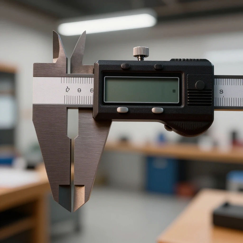
Total Indicated Runout is measured using a dial test indicator placed against the internal or external surface of a rotating spindle. For most home metalworking projects, a TIR of 0.0005 to 0.001 inches is acceptable, but high-precision work often requires even tighter tolerances.
- Clean the Surface: Any dust or oil on the spindle will give a false reading.
- Mount the Indicator: Use a magnetic base to secure the dial indicator to the machine frame.
- Rotate Slowly: Turn the spindle by hand through a full 360-degree rotation.
- Note the Deviation: The difference between the highest and lowest points on the dial is your TIR.
-
Check the Taper: Always measure the runout inside the spindle taper as well as on the outside nose.
-
Spindle Bearing Lifetimes: The lifespan of a bearing is heavily dictated by its “Preload.” This is the amount of pressure applied to the bearing during assembly to remove internal play. Too much preload causes overheating; too little causes chatter.
| Bearing Style | Radial Load Capacity | Axial Load Capacity | Precision Level |
|---|---|---|---|
| Deep-Groove Ball | Moderate | Low | Standard |
| Angular Contact | High | High | High Precision |
| Tapered Roller | Very High | Very High | Heavy Duty/Rigid |
Evaluating Linear Motion Systems and Bedway Alignment
The “ways” of a machine are the precision-ground surfaces that allow parts like the carriage or table to move smoothly and accurately. In home metalworking tools, these are usually “V-ways” or “dovetail ways” cast directly into the frame. The quality of the grinding and the fit of the “gibs”—adjustable brass or steel strips—determine how much play is in the system.
I’ve seen many machines where the ways look beautiful but are not actually parallel. This results in a tool that is tight at one end of its travel and loose at the other. When evaluating a machine, you should move the table through its entire range of motion. If you feel “tight spots,” it usually indicates a geometry error in the casting or grinding process.
Understanding Backlash and Gib Adjustment
Backlash is the “lost motion” that occurs when you reverse the direction of a handwheel before the machine part actually starts moving. This is caused by the small gap between the threads of the leadscrew and the nut. While some backlash is normal in manual machines, it must be consistent and adjustable.
- Gib Strips: These are the components used to take up the slack between sliding surfaces; look for machines that use “tapered gibs” rather than “screw-adjusted flat gibs” for better consistency.
- Leadscrew Accuracy: The precision of the threads on the main drive screws; industrial standards often look for less than 0.001 inch of error over a 12-inch span.
- Way Wipers: Check if the machine includes felt or rubber wipers to keep metal chips from getting trapped between the sliding surfaces, which causes rapid wear.
Navigating the Realities of Parts Availability and Long-Term Maintenance
No matter how well-built a machine is, components like belts, capacitors, and gears will eventually wear out. One of the biggest mistakes I see fabricators make is buying a specialized tool without checking the availability of replacement parts. A machine becomes a very heavy paperweight if you cannot find a replacement for a proprietary drive gear or a specific spindle bearing.
I always recommend looking for machines that use “off-the-shelf” components where possible. For example, a motor with a standard NEMA frame size is much easier to replace than a custom-molded motor integrated into the machine housing. Similarly, check if the bearings use standard ISO part numbers that can be sourced from local industrial supply houses.
Creating a Spare Parts Strategy
Before you finalize a purchase, research the manufacturer’s support history. Some companies provide detailed exploded-view diagrams and online parts ordering, while others require you to go through a dealer network that may or may not stock what you need.
- Identify Wear Items: Belts, brushes, and plastic “shear gears” (designed to break before the motor does) should be kept on hand.
- Verify Bearing Numbers: Search for the bearing codes in the manual to see if they are common sizes.
- Check Controller Compatibility: If the speed controller fails, can it be replaced with a generic VFD?
-
Document the Manuals: Download and print the technical specifications and wiring diagrams immediately, as they often disappear from websites over time.
-
Standard Metric vs. Imperial Hardware: Ensure you have the correct toolset to maintain the machine; most modern small-scale machinery uses metric fasteners and fittings.
Essential Accuracy Benchmarks for Machine Selection
When you are comparing two different models, it helps to have a checklist of hard numbers. These benchmarks are based on standard machining tolerances that allow for high-quality fabrication without requiring laboratory-grade conditions.
- Bedway Parallelism: The ways should be parallel within 0.001 inches over the entire length of the bed.
- Tailstock Alignment: On a lathe, the tailstock center should align with the headstock center within 0.002 inches vertically and horizontally.
- Table Flatness: On a milling machine, the table surface should be flat within 0.001 inches across its width.
- Motor Temperature Rise: After 30 minutes of unloaded running, the motor should not be too hot to touch (typically staying below 140°F or 60°C).
By focusing on these mechanical realities—the quality of the iron, the sophistication of the motor drive, and the precision of the spindle—you can bypass the marketing hype. A machine that is built on sound engineering principles will provide decades of service and allow you to produce work that meets professional standards in your own workshop.
Frequently Asked Questions
What is the difference between a brushed and brushless motor in metalworking?
Brushed motors use physical carbon brushes to transfer electricity to the spinning part of the motor. They are simpler and cheaper but the brushes wear out and they tend to lose torque at low speeds. Brushless DC (BLDC) motors use electronic controllers to manage the magnetic fields. They are more efficient, offer much higher torque at low RPM, and require less maintenance because there are no brushes to replace.
Why is machine weight so important for metal fabrication?
Weight equals mass, and mass dampens vibration. When a cutting tool hits metal, it creates a series of high-frequency shocks. If the machine is light, those shocks travel through the frame and cause the tool to bounce, leading to “chatter.” A heavy cast-iron frame absorbs these vibrations, resulting in a smoother surface finish and longer tool life.
How much spindle runout is too much for a home workshop?
For general fabrication and repair work, a Total Indicated Runout (TIR) of 0.001 inches or less is the goal. If the runout exceeds 0.003 inches, you will struggle with accuracy, as drill bits will wander and turned parts will not be concentric. High-precision work usually requires a TIR of 0.0005 inches or better.
What are “ways” and why do they need to be hardened?
“Ways” are the precision-ground tracks that the moving parts of a machine slide along. They are often “flame-hardened” or “induction-hardened” to make the surface resistant to wear and scratches from metal chips. Hardened ways stay accurate for much longer than soft, unhardened cast iron.
Can I run a 3-phase industrial motor in a residential garage?
Yes, you can use a Variable Frequency Drive (VFD). A VFD takes single-phase power from your wall outlet and converts it into 3-phase power for the motor. This also gives you the added benefit of electronic speed control and “soft-start” capabilities, which reduce the electrical load when the machine turns on.
What is “backlash” and can it be removed entirely?
Backlash is the play between a leadscrew and its nut. It can almost never be removed entirely in manual machines because some clearance is needed for the screw to turn. However, it can be minimized through gib adjustments or by using “anti-backlash” nuts. Most manual machinists simply learn to “dial out” the backlash by always approaching their measurement from the same direction.
Is a gear-driven headstock better than a belt-driven one?
Gear-driven headstocks provide maximum torque and are great for heavy-duty cutting, but they can be noisy and may break a gear if the machine crashes. Belt-driven headstocks are much quieter and the belt acts as a safety “fuse” by slipping if the tool gets stuck. For most home users, modern high-torque belts are more than sufficient.
How do I check if a used machine is still accurate?
Bring a dial test indicator and a precision ground “test bar.” Place the bar in the spindle and measure the runout. Move the carriage or table across its full range and watch for deviations on the indicator. If the needle jumps or moves significantly, the ways may be worn or the machine may be out of alignment.
(This article was written by one of our staff writers, Steven Brooks. Visit our Meet the Team page to learn more about the author and their expertise.)