How to Build a Steel Ladder Rack for Truck Beds (DIY Guide)
I remember the first time I tried to build a heavy-duty frame for my old pickup. I had measured everything three times, used a brand-new abrasive saw, and felt confident as I started laying down beads. Halfway through, I noticed the back right corner was lifting off the table. By the time I finished, the entire structure had twisted by nearly half an inch. It was a humbling lesson in how heat moves metal. After 13 years as a prototype technician, I’ve learned that successful custom fabrication projects aren’t just about the quality of your welds; they are about how you manage the physics of the build.
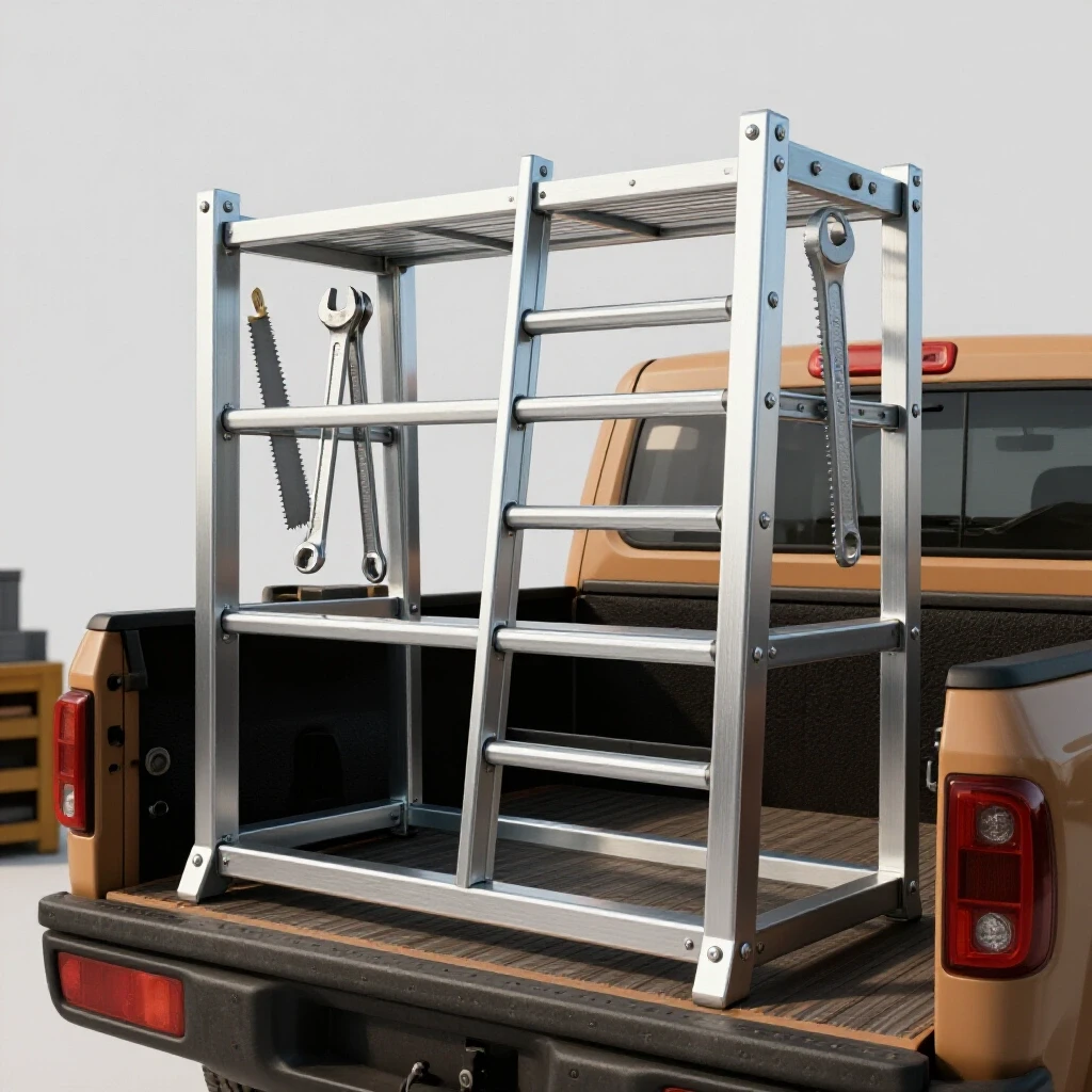
When you are constructing a utility frame to carry heavy loads like extension ladders or lumber, the stakes are higher than a simple workbench. You are dealing with long spans of square tubing that love to bow and twist the moment you pull the trigger on your MIG gun. To get a professional result in a home garage, you need a plan that accounts for material behavior, accurate layout fixtures, and a disciplined weld sequencing layout.
Engineering a Solid Foundation with Accurate Cut Lists
A cut list is a detailed inventory of every metal piece needed for the build, accounting for total length and waste. Creating one ensures you buy enough material and helps you visualize how parts fit together before the first spark flies. This document serves as your roadmap, preventing mid-project trips to the steel yard because of a forgotten brace.
When I start a project, I always account for the thickness of the material itself. If you are using 2-inch square tubing with a .120-inch wall thickness, your internal dimensions change depending on whether you are butt-welding or miter-cutting your corners. For a truck bed application, I prefer miter cuts at 45 degrees for the top corners. This seals the tube ends from moisture and provides a cleaner look, though it requires more precision during the cutting phase.
Calculating Kerf for Tight Fit-Ups
Kerf is the width of the gap made by a cutting tool, such as a saw blade or torch. If you ignore this 1/16 to 1/8 inch of lost metal, your final assembly will be shorter than planned, leading to gaps that weaken your welds. In my shop, I always mark my “keep” side of the line and ensure the blade falls on the waste side.
| Cutting Tool | Average Kerf Width | Dimensional Tolerance |
|---|---|---|
| Abrasive Chop Saw | 1/8″ (0.125 in) | +/- 1/16″ |
| Cold Saw | 3/32″ (0.093 in) | +/- 1/32″ |
| Portaband (Handheld) | 1/16″ (0.062 in) | +/- 1/8″ |
| Plasma Cutter | 1/16″ to 3/32″ | +/- 1/16″ |
When planning your cuts, I recommend adding at least 10% to your total linear footage for “drops” or waste. For a standard 6.5-foot truck bed, you will likely need four uprights, two long top rails, and at least three cross members. Using a dedicated cutting calculator or even a simple spreadsheet helps keep these numbers straight.
Building Workshop Jigs for Repeatable Results
Jigs are temporary fixtures that hold your metal pieces in the exact position required during the tacking and welding phases. They act as a second set of hands, ensuring that every angle remains at a true 90 degrees while the metal undergoes thermal stress. Without them, the cooling weld metal will pull your joints out of square.
I don’t always have a professional 5×10-foot welding table with precision holes. Instead, I often build “bridge jigs” out of scrap angle iron. For a truck-based project, the most critical jig is the one that holds your uprights at the correct angle relative to the bed rails. Most truck beds have a slight taper or a specific stake pocket alignment. I suggest building a base template using the truck bed itself as a guide, then moving that template to your flat workspace.
Utilizing Metal Layout Tips for Precision
Metal layout tips involve using specialized tools like machinist squares, scribe lines, and layout fluid to mark your steel. Unlike a pencil on wood, a scribe line on steel won’t rub off and provides a much finer point for your saw blade to follow. I use a carbide-tipped scriber for all my marks to ensure a tolerance of within 1/32 of an inch.
- Always measure from a single “datum” or reference point to avoid cumulative error.
- Use a large framing square to check the “3-4-5” rule on your main frame.
- Clamp your workpieces to your table using heavy-duty C-clamps or F-clamps every 12 to 18 inches.
- Check for “wind” (twisting) by sighting across two level bars placed at opposite ends of the frame.
Managing Thermal Distortion and Weld Sequences
Weld sequencing is the specific order in which you apply heat to a joint to balance the pulling forces of cooling metal. By jumping between different areas of the frame, you counteract shrinkage and keep the structure from twisting out of alignment. This is the most overlooked phase of custom fabrication projects.
When steel is heated to a molten state, it expands. As it cools, it contracts with immense force. If you weld the entire outside of a joint first, the cooling metal will pull the upright inward. To combat this, I use a “staggered” approach. I might weld the front left corner, then move immediately to the back right corner. This distributes the heat across the entire mass of the steel rather than concentrating it in one area.
Why Weld Shrinkage Warps Square Structures
Angular weld shrinkage occurs when the weld bead on one side of a joint contracts more than the other, creating a hinge effect. In a 90-degree joint, the weld on the “inside” of the corner will try to pull the joint closed to 88 or 89 degrees. To prevent this, I often “preset” my joints by clamping them at 91 degrees, knowing they will pull back to a perfect 90 as they cool.
| Joint Type | Potential Distortion | Mitigation Strategy |
|---|---|---|
| T-Joint (Fillet) | Angular Pull (Leaning) | Weld both sides in short increments |
| Butt Weld | Longitudinal Shrinkage | Leave a 1/16″ root gap |
| Corner Weld | Diamonding (Out of Square) | Heavy tacking on all four corners |
| Lap Joint | Bowing/Cambering | Use intermittent (stitch) welds |
Implementing Structural Tacking Strategies
Tacking involves making small, temporary welds to hold the assembly together before the final beads are laid. Proper tacking prevents the metal from shifting during the main welding process and allows for minor adjustments if the layout is slightly off. I’ve seen many builders ruin a project by laying full beads before verifying the entire assembly is square.
For 1/8-inch wall tubing, your tacks should be about 1/4 inch long and placed at every corner of the joint. I usually place four tacks per joint on square tubing—one in the center of each face. If I’m building a long rail for a truck bed, I’ll tack the entire structure together first, then measure the diagonals. If the diagonals are within 1/16 of an inch, I proceed to the final weld sequencing layout.
Tack Spacing and Sizing Benchmarks
- Tack Size: 2x to 3x the thickness of the base metal.
- Spacing: For long flat bars or plates, space tacks every 3 to 4 inches.
- Verification: Always use a rubber mallet to “persuade” tacked joints into alignment before final welding.
- Sequence: Tack the “neutral axis” (the center) first to minimize initial movement.
Executing the Final Weld Sequence
Once the frame is tacked and checked for square, it’s time for the final passes. I follow a specific order: I weld the flats first, then the verticals, and finally the overheads if necessary. However, the most important rule is to never finish a single joint completely before moving to the next.
- Weld 1 inch on the outside of Corner A.
- Move to the opposite side of the frame and weld 1 inch on the outside of Corner D.
- Return to Corner B and weld the inside.
- Move to Corner C and weld the inside.
This “X-pattern” is a classic metal warping solution. It keeps the heat input symmetrical. If you feel the metal getting too hot to touch (over 400-500 degrees Fahrenheit) near the joint, stop and let it air cool. Quenching with water is a rookie mistake; it can make the steel brittle and cause immediate cracking in the heat-affected zone (HAZ).
Final Fitment and Mounting in the Truck Bed
Mounting is the process of securing the finished steel structure to the bed rails of the pickup. This step requires careful drilling and the use of backing plates to distribute the load evenly, preventing the thin sheet metal of the truck from cracking under stress. Modern trucks often have aluminum or thin-gauge steel beds, making load distribution critical.
I prefer using 1/4-inch thick flat bar for the mounting “feet” that sit on the bed rails. These should be at least 12 to 18 inches long to spread the weight of the ladders or cargo. When drilling your mounting holes, use a center punch to prevent the bit from walking. I also recommend using Grade 8 hardware with large fender washers or custom-cut backing plates underneath the bed rail to sandwich the sheet metal securely.
Post-Weld Alignment and Straightening
Even with the best fixtures, some movement is inevitable. If a long top rail has developed a slight bow, you can often correct it using “flame straightening” or mechanical force. I keep a 20-ton hydraulic jack and some heavy chains in the shop for this purpose. By applying pressure in the opposite direction of the warp and letting it sit overnight, you can often recover a straight line.
- Check the “plane” of the mounting feet to ensure they sit flat on the bed rails.
- Grind down any high spots on the welds that might interfere with cargo.
- Apply a high-quality zinc-rich primer or have the assembly powder-coated to prevent rust.
- Document the final dimensions in a post-weld log to see where the metal moved most for future reference.
Conclusion and Next Steps
Building a durable, straight utility rack is a masterclass in heat management and patience. By prioritizing your workshop jigs and fixtures and following a strict weld sequencing layout, you can produce a professional-grade structure that rivals any commercial product. The key is to respect the metal; it is a dynamic material that reacts to every calorie of heat you put into it.
Your next step should be to clear a flat area in your shop and start your cut list. Measure your truck bed at the front, middle, and rear, as many beds are not perfectly rectangular. Once you have your dimensions, source your square tubing and start practicing your miter cuts. Remember, the time you spend on the layout is three times more valuable than the time you spend welding.
FAQ: Common Challenges in Metal Fabrication
How do I prevent the square tubing from twisting when I weld the cross members?
Twisting, or “torsional warp,” usually happens when you weld one side of the tube completely before the other. To prevent this, place heavy tacks on opposite corners (top-left and bottom-right) first. Use a “backstepping” technique where you weld in short segments, moving in the opposite direction of the overall bead travel.
What is the best material thickness for a utility rack?
For most DIY truck projects, 1.5-inch or 2-inch square tubing with a .120-inch (1/8″) wall thickness is the “sweet spot.” It provides excellent structural integrity without adding excessive weight to the vehicle. Using .083-inch wall tubing is lighter but much harder to weld without burning through or causing significant warping.
Can I build this project without a dedicated welding table?
Yes, but you need to create a level plane. You can use two heavy-duty sawhorses and a pair of straight “strongbacks” (long pieces of thick channel or I-beam) to create a temporary fixture. Always use a level and string lines to ensure your sawhorses haven’t shifted during the build.
Why do my miter joints always have a gap on one side?
This is usually caused by “blade deflection.” When a chop saw blade hits the metal at an angle, it can flex outward. To fix this, slow your cut speed and ensure your material is clamped as close to the blade as possible. Also, check that your saw’s fence is actually square to the blade using a machinist square.
How much gap should I leave between pieces for a good weld?
For 1/8-inch material, a “tight fit” (no gap) is acceptable for MIG welding, but a small 1/32-inch gap ensures better root penetration. If the gap exceeds 1/8 inch, you risk excessive heat buildup and warping as you try to “bridge” the hole with weld metal.
Is it better to bolt or weld the rack to the truck?
I always recommend bolting. Welding directly to the truck bed is permanent and can damage the vehicle’s corrosion protection. Bolting with backing plates allows you to remove the rack if you need to haul oversized items or sell the vehicle later.
How do I know if my weld sequence is working?
Keep a digital protractor or a framing square handy. After every couple of inches of welding, check the angle. If you see the joint moving from 90 to 89 degrees, stop welding that side and move to the opposite side to “pull” it back.
What should I do if the frame is “diamonding”?
If the frame is no longer square (one diagonal is longer than the other), you can use a ratcheting cargo strap. Hook the strap to the corners of the long diagonal and tension it until the measurements match. While under tension, add more structural tacks or gussets to lock it into the correct shape.
How do I deal with the “mill scale” on hot-rolled steel?
Mill scale is the dark grey coating on new steel. It is an insulator and will cause arc instability and porous welds. Use a flap disc on an angle grinder to clean the steel to “bright metal” at least one inch back from every weld zone.
Should I use gussets on the corners?
Absolutely. Triangular gussets made from 3/16-inch plate significantly increase the rack’s resistance to “racking” (side-to-side swaying) when the truck is in motion. Place them at the junction of the uprights and the top rails for maximum benefit.
(This article was written by one of our staff writers, Robert Kline. Visit our Meet the Team page to learn more about the author and their expertise.)