How to Build an Anti-Sag Steel Fence Gate (Step)
I remember the first time I tried to weld a square frame. I was three years into my self-taught journey, and I thought I had it figured out. I spent hours cutting the steel, clamped everything down, and ran what I thought were decent beads. But the moment I hung that gate, it dipped three inches. It didn’t just sag; it mocked me. That failure taught me that a rigid metal structure isn’t just about the metal you use; it is about the physical consistency of your technique and your understanding of how heat affects geometry.
For those of you currently spending your weekends in the shop, tracking your bead consistency and trying to stop your torch hand from shaking, I want you to know that the frustration you feel is part of the process. Mastering torch control and learning metal fabrication is not about a single “aha” moment. It is about the hundreds of hours spent refining your muscle memory. In this guide, we are going to use the project of building a rigid, sag-resistant steel gate as a roadmap to improve your technical proficiency. We will focus on the physical cues, the math of the puddle, and the structural habits that separate a hobbyist from a professional fabricator.
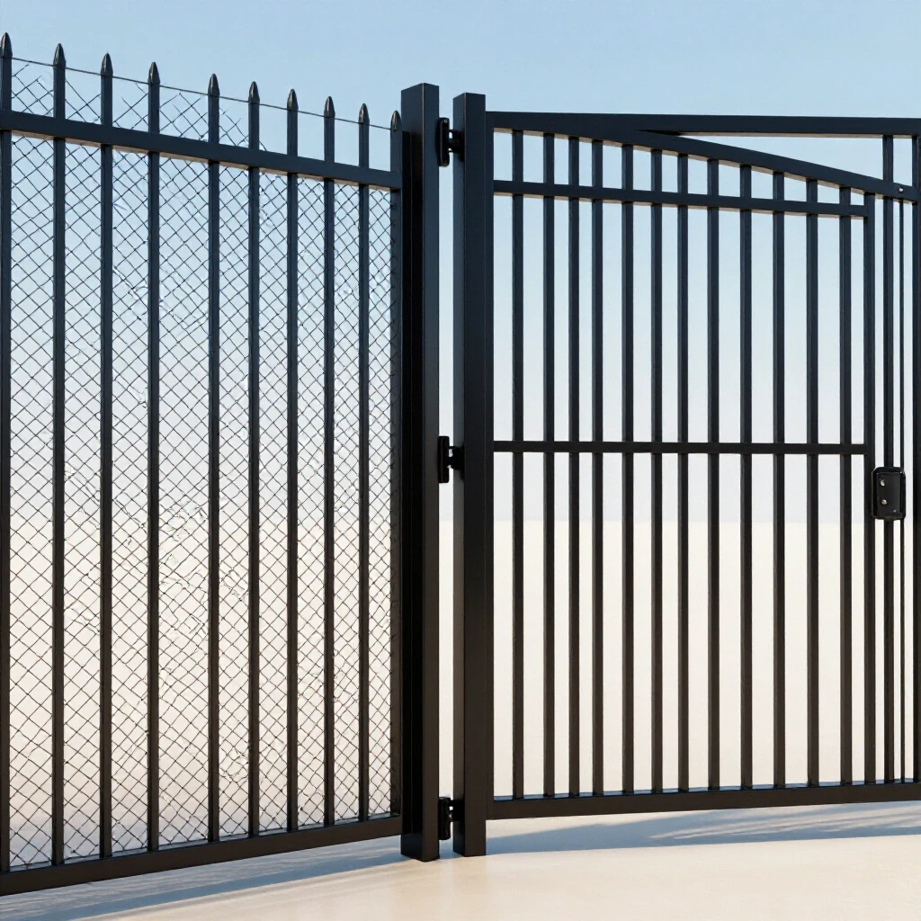
Establishing a Stable Foundation Through Body Mechanics
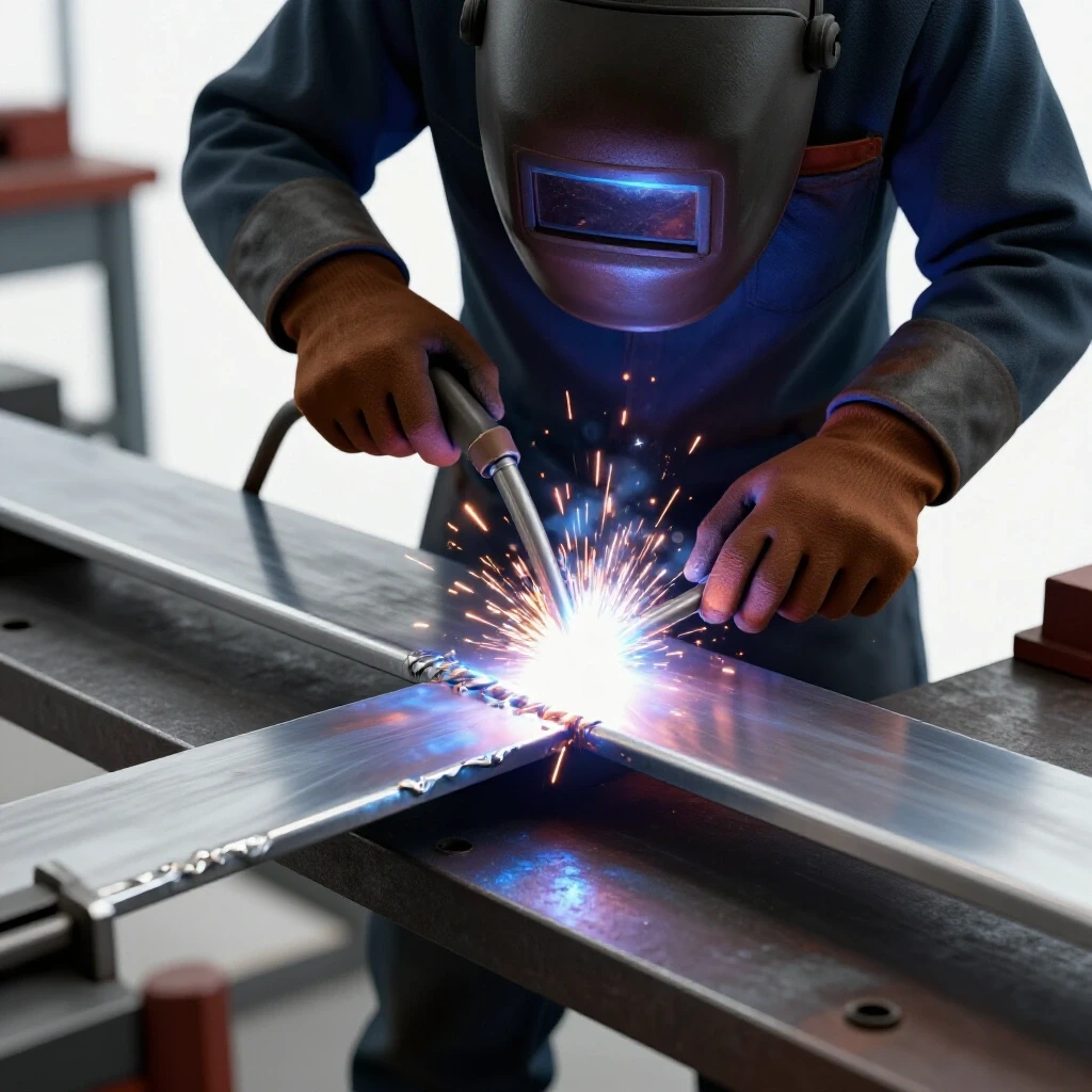
Body mechanics in welding refers to the intentional positioning of your torso, arms, and hands to create a stable “tripod” for your torch. Proper ergonomics minimize fatigue and allow for the micro-adjustments needed to maintain a consistent arc length. Without a stable base, your travel speed will fluctuate, leading to uneven penetration and structural weak points.
When I started, I used to “free-hand” my welds, hovering my arm in the air like a painter. My beads looked like a topographical map of a mountain range. Now, I teach students to find three points of contact. If you are welding the corner of a gate frame, your feet are your first two points, and your non-dominant hand or elbow resting on the worktable is the third. This “welder’s stance” allows you to pivot from the waist rather than moving your arm muscles, which are prone to twitching.
Before you even pull the trigger, perform a “dry run.” Move your torch across the entire joint without welding. If your arm hits an obstruction or your cord snags at the halfway point, you will lose your puddle. A smooth, uninterrupted physical motion is the secret to a professional-grade bead.
| Component | Physical Cue | Target Sensation |
|---|---|---|
| Feet | Shoulder-width apart | Grounded, weight slightly forward |
| Elbows | Tucked against the ribs | “Locked in” but not tense |
| Wrist | Neutral and relaxed | Fluidity in the “flick” or “oscillation” |
| Neck | Angled to see the leading edge | Clear view of the puddle “toe” |
Setting Machine Parameters for Structural Integrity
Machine parameters are the specific settings on your welder—voltage, wire feed speed, or amperage—that dictate how the metal melts and fuses. Getting these right is the first step in a metal welding practice guide because it ensures the heat input matches the material thickness. Incorrect parameters lead to cold laps or burn-through, both of which cause structural failure.
For a standard gate frame made of 2-inch square tubing (1/8-inch wall), you need to find the “sweet spot” where the wire melts into the base metal without piling up on top. I recommend starting with a “bead-on-plate” drill. Take a scrap piece of the same tubing and run 3-inch beads.
If you hear a sound like bacon frying, you are close. If it sounds like a machine gun, your wire speed is too high. If it’s a soft hiss, your voltage might be too high, risking a “long arc” that creates porosity. Use the table below as a baseline for 1/8″ steel using MIG (GMAW) with .030 wire and 75/25 gas.
Baseline MIG Parameters for 1/8″ Square Tubing
- Voltage: 17–19 Volts
- Wire Feed Speed: 210–240 Inches Per Minute (IPM)
- Gas Flow: 20–25 Cubic Feet Per Hour (CFH)
- Stick-out: 3/8″ (The distance from the contact tip to the metal)
Geometry and Squaring for Long-Term Rigidity
Squaring is the process of ensuring all four corners of a frame are exactly 90 degrees and that the parallel sides are equal in length. In fabrication, “close enough” is the enemy of a functional gate. A frame that is out of square by even 1/8 of an inch will bind at the hinges and sag under its own weight over time.
I learned the hard way that steel moves when it gets hot. You can clamp a frame perfectly square, but as the weld cools, it shrinks and pulls the metal toward the joint. This is called “draw.” To combat this, you must master the “tack and check” method.
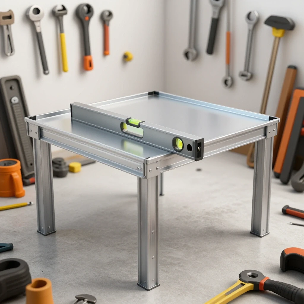
First, clean your “clean zones”—the two inches surrounding every joint—down to shiny silver metal using a flap disc. Any mill scale or rust left behind will insulate the metal, causing inconsistent arc starts. Once clean, place a small, high-heat tack weld on the outside corner of the joint. Check for square using a speed square or by measuring the diagonals of the frame. If the diagonal measurements are identical, the frame is square. Only then should you proceed to the structural welds.
The Physics of the Diagonal Cross-Brace
A diagonal cross-brace is a structural member that runs from one corner of a frame to the opposite corner, turning a floppy rectangle into two rigid triangles. This is the most critical element in preventing gravitational sag. Triangles are the only geometric shape that cannot be deformed without changing the length of one of its sides.
When you install this brace, orientation matters. In a gate, you want the brace to run from the bottom hinge corner up to the top latch corner. This puts the brace in “compression.” Steel is incredibly strong when it is being pushed together. If you run the brace from the top hinge down to the bottom latch, the weight of the gate puts the brace in “tension,” trying to pull the welds apart.
While both can work if the welds are perfect, a compression brace is much more forgiving for intermediate fabricators. It physically props up the outer edge of the gate, transferring the weight directly back into the bottom hinge and the post.
Compression vs. Tension Bracing
- Compression Brace: Bottom hinge to top latch. (Recommended)
- Tension Brace: Top hinge to bottom latch. (Requires higher weld tensile strength)
- Angle of Brace: Ideally between 30 and 60 degrees for maximum load distribution.
Mastering Torch Control and Puddle Management
Torch control is the ability to maintain a consistent distance and angle while moving the weld puddle along a joint. This requires a high level of hand-eye coordination and “reading the puddle,” which means watching the molten metal to see if it is wetting into the edges properly. This is where trade school practice drills really pay off.
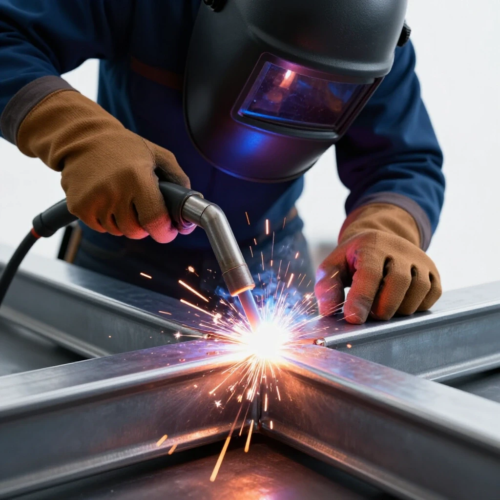
When welding the corners of your gate, focus on your “Travel Angle” and “Work Angle.” For a flat butt joint, your work angle should be 90 degrees (straight up and down). Your travel angle should be a 10 to 15-degree “drag” or “push.” I prefer a slight push for MIG on thin tubing because it allows me to see exactly where I am going.
One of the biggest hurdles for my students is “Weld Travel Speed.” If you go too slow, you dump too much heat into the metal, causing it to warp. If you go too fast, the bead stays on the surface and doesn’t penetrate. Aim for a speed of about 8 to 12 inches per minute. You can practice this by marking a 10-inch line on a plate and timing yourself to see if you can traverse it in exactly 60 seconds.
| Joint Type | Work Angle | Travel Angle | Motion Pattern |
|---|---|---|---|
| Butt Joint | 90° | 10-15° Push/Drag | Straight stringer |
| Fillet (T-Joint) | 45° | 10-15° Drag | Slight “C” or “J” motion |
| Corner Joint | 45° | 5-10° Push | Tight “Z” weave |
Strategic Hinge Placement for Load Management
Hinges are the fulcrum points where the gate’s weight meets the stationary post. If hinges are undersized or poorly positioned, the gate will sag regardless of how rigid the frame is. In metal fabrication, we use heavy-duty barrel hinges or “bullet” hinges that are welded directly to the frame.
I always tell my students to place the top hinge as high as possible and the bottom hinge as low as possible. This increases the “moment arm,” which reduces the prying force on the top hinge. When welding hinges, heat management is crucial. If you get the barrel too hot, you can warp the internal pin, making the gate squeak or seize.
Use short “stitch welds”—welding one inch, letting it cool, then welding the next—to keep the heat low. Always ensure the hinges are perfectly vertical. If the top hinge is even slightly further out than the bottom one, the gate will swing open or shut on its own due to gravity.
Tracking Your Technique Progression
The difference between a hobbyist and a professional is the use of data. I encourage everyone to keep a “Welding Technique Progression” log. After every practice session or project, take a photo of your best and worst beads. Note the settings you used and how the metal reacted.
When I was learning, I struggled with “undercut”—a defect where the weld eats a groove into the base metal but doesn’t fill it back up. By logging my attempts, I realized I was holding too long of an arc. I adjusted my “stick-out” to a consistent 3/8″, and the problem vanished. You cannot fix what you do not measure.
Sample Practice Log Template
- Date: [Current Date]
- Material: 1/8″ Square Tubing
- Process: MIG (.030 wire, 75/25 gas)
- Settings: 18.5V / 225 IPM
- Focus Area: Maintaining 45-degree work angle on fillet welds.
- Observation: Beads are flatter today; travel speed was more consistent. Still seeing some spatter at the start of the arc.
- Goal for Next Session: Clean the ground clamp area better to improve arc start.
Overcoming the Technical Plateau
If you find yourself stuck—where your welds aren’t getting better despite more practice—you are likely at a technique plateau. This usually happens because you are repeating the same physical mistakes. To break through, you need to change your perspective.
I highly recommend using a smartphone to record slow-motion video of your welding. Set it up behind a welding lens or use a dedicated “weld cam” filter. When you watch the footage, you will see things you missed in real-time: the puddle flickering, the wire hitting the front of the puddle instead of the center, or your hand shaking as you reach the end of the joint.
Analyzing your own physical movement is the fastest way to build the muscle memory required for professional results. Don’t be afraid to go back to basic “bead-on-plate” drills. Even after 12 years, I still start my day with a few practice runs on scrap metal to “calibrate” my hands.
Final Steps for a Durable Finish
Once the welding is complete and the frame is square and braced, the final step is cleanup. Use a 60-grit flap disc to smooth out any high spots on your welds, but be careful not to grind the weld flat. A weld’s strength comes from its “throat” or thickness. If you grind it flush with the tubing, you are removing the very material that holds the gate together.
Apply a high-quality zinc-rich primer to all welded areas immediately. The heat from welding destroys the factory coating on the steel, leaving it vulnerable to rust within hours. This isn’t just about aesthetics; rust between the hinge and the frame will eventually lead to structural failure. By following these systematic steps—from body positioning to heat management—you aren’t just building a gate; you are building the physical skills that define a master fabricator.
Frequently Asked Questions
Why does my gate still sag even with a diagonal brace? Sagging often occurs if the brace is not fit tightly before welding. If there is a gap between the brace and the frame, the weld will shrink as it cools, pulling the frame out of square. Ensure a “press-fit” where the brace must be lightly tapped into place.
What is the best weld travel speed for 1/8″ steel? For most beginners, a speed of 8 to 12 inches per minute (IPM) is ideal. This allows enough time for the puddle to wet into the edges without overheating the thin-walled tubing.
How do I prevent the frame from warping during welding? Use the “balanced welding” technique. Instead of welding one corner completely, place tacks on all four corners. Then, weld the top of corner A, then the bottom of corner C (the opposite corner). Distributing the heat prevents the entire frame from pulling in one direction.
Should I push or drag my MIG torch? For thin materials like gate tubing, “pushing” (pointing the torch in the direction of travel) produces a flatter bead and less penetration, which helps avoid burn-through. “Dragging” produces deeper penetration and a narrower bead, which is better for thicker plate steel.
How much gap should I leave between the gate and the post? A standard gap is 1/2 inch to 1 inch, depending on the hinge type. Always account for the thickness of the hinge itself. It is better to have a slightly larger gap that you can fill with a latch than a gap so tight the gate won’t close when the metal expands in the summer heat.
What is “mill scale” and why must I remove it? Mill scale is the dark grey flaky layer on hot-rolled steel. It is an electrical insulator and contains impurities. If you don’t grind it off, your arc will be unstable, and your welds will have “porosity” (tiny holes), making them weak.
How can I tell if my weld has good penetration? On 1/8″ tubing, look at the inside of the tube (if possible) or the back of a test plate. You should see a slight discoloration or a small “heat tint” indicating the metal reached its melting point all the way through. If the back of the metal looks untouched, your heat was too low.
What is the “Clean Zone” in fabrication? The clean zone is the area approximately 1 to 2 inches around the joint that has been ground down to bare, shiny metal. This ensures a consistent arc and prevents contaminants from being sucked into the molten puddle.
How do I fix a frame that has pulled out of square? If the frame is only slightly out of square, you can often “heat-straighten” it. Apply heat to the side opposite of the pull. As the metal cools, it will shrink and pull the frame back toward the center. This is an advanced technique that requires careful monitoring.
Why is my wire sticking to the contact tip? This is known as a “burn-back.” It usually happens because your wire feed speed is too low or your “stick-out” (distance from the tip to the work) is too short. Increase your wire speed or hold the torch slightly further away.
(This article was written by one of our staff writers, Thomas Langley. Visit our Meet the Team page to learn more about the author and their expertise.)