How to Press Bearings onto Steel Shafts Safely (DIY Guide)
I have spent nearly two decades in workshops, often standing over a piece of equipment that refuses to cooperate. There is a specific kind of frustration that sets in when a high-precision component, like a bearing, gets stuck halfway down a shaft. You can feel the resistance in the tool, and you know that if you apply just a bit more “uneducated” force, you will likely score the shaft or ruin the race. My background in millwright work and industrial fabrication has taught me that these moments are not failures of strength, but failures of preparation and diagnostics. Mastering the art of seating a precision component onto a steel spindle requires a blend of mechanical engineering principles and a steady, methodical hand.
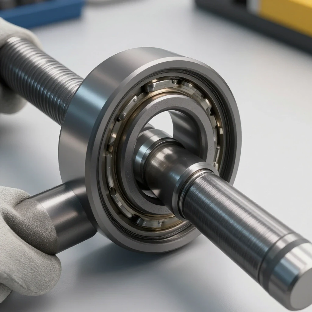
In my experience, the difference between a machine that runs for ten years and one that vibrates itself to pieces in ten days often comes down to the first few minutes of assembly. When we talk about manual assembly methods, we are looking at a process where every thousandth of an inch matters. If you have ever dealt with tool chatter on a lathe or mysterious porosity in a critical weld, you know that the “invisible” variables are the ones that cause the most trouble. The same logic applies here. We are going to break down the systematic steps to ensure your mechanical assemblies are executed with the precision of a factory floor, using only the tools found in a well-equipped service shop.
Why Precision Measurement Precedes Every Mechanical Assembly
Precision measurement is the process of using calibrated tools to verify that the physical dimensions of two mating parts fall within the engineered tolerances required for a functional fit. This step ensures that the interference between the shaft and the bearing bore is sufficient to prevent slipping without being so tight that it causes material galling or internal component stress.
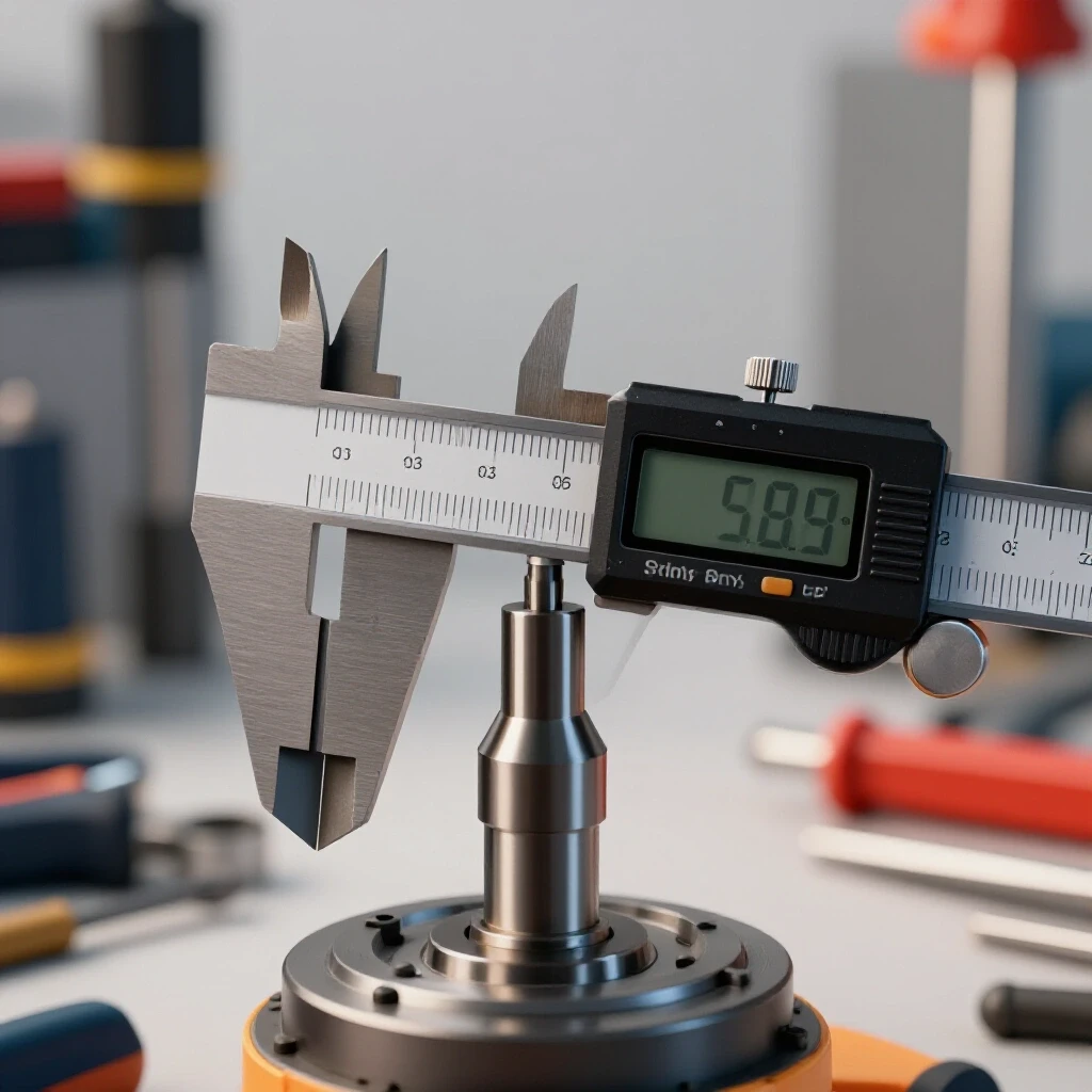
Before I even reach for a press or a threaded rod, I reach for my micrometers. You cannot guess an interference fit. In the world of mechanical troubleshooting, we rely on the “diametral interference” value. For most standard steel shafts, you are looking for a fit that is between 0.0005 and 0.0015 inches of interference per inch of shaft diameter. If your shaft measures 1.001 inches and your bearing bore is 1.000 inches, you have a 0.001-inch interference.
I once worked on a pump rebuild where the previous technician had simply “sanded” the shaft until the bearing felt like it would fit. This is a recipe for disaster. By removing material without measuring, he created an out-of-round condition that led to massive vibrational harmonics once the pump hit 3,600 RPM. Always use a T-gauge or an inside micrometer for the bearing bore and an outside micrometer for the shaft. Record these numbers in a log. If the shaft is oversized beyond the 0.0015-inch threshold, the force required to seat the component will exceed the structural limits of the inner race.
Establishing the Interference Fit Baseline
To help visualize these requirements, I follow a specific set of benchmarks based on standard machining tolerances. These values ensure the assembly remains stable under load without requiring industrial-grade force.
- Shaft Diameter 0.5″ to 1.0″: Target interference of 0.0003″ to 0.0007″.
- Shaft Diameter 1.0″ to 2.0″: Target interference of 0.0005″ to 0.0012″.
- Shaft Diameter 2.0″ to 4.0″: Target interference of 0.0010″ to 0.0020″.
Building on this, you must also inspect the shaft for “high spots” or burrs. Even a microscopic burr from a previous set screw can act like a wedge, tilting the bearing as it begins its travel. I use a fine Arkansas stone or 600-grit emery paper to lightly polish the lead-in chamfer of the shaft. This lead-in, usually a 15-to-30-degree bevel, is the most critical half-inch of the entire shaft.
Eliminating Misalignment with Guided Manual Fixtures
Misalignment occurs when the centerline of the bearing bore is not perfectly parallel with the centerline of the shaft during the initial seating process. This creates an angular error that focuses all the assembly force on a single point of the race, often leading to “cocking” or permanent deformation of the mating surfaces.
One of the most common “electrical gremlins” in a motor is actually a mechanical alignment issue. When a bearing is pressed on crooked, it creates an uneven load on the motor’s rotor. This leads to an unbalanced magnetic pull, which can look like a power phase issue on a diagnostic meter. To avoid this, I use a simple DIY threaded-rod fixture. This tool allows for a slow, controlled descent that a hammer and drift can never replicate.
The fixture consists of a high-tensile threaded rod (Grade 8 is preferred), two heavy-duty washers, and a “pilot” sleeve. The pilot sleeve should be a piece of pipe or a custom-turned bushing that matches the diameter of the inner race exactly. By tightening the nuts on the threaded rod, you apply a linear, axial force that pulls the bearing onto the shaft. Because the rod passes through the center of the shaft (if hollow) or is used in a bridge fixture, the force is naturally centered.
The Diagnostic Path for Alignment Checks
If you feel the resistance spike suddenly during the first 1/8th inch of travel, stop immediately. This is a primary diagnostic indicator of misalignment.
- Visual Gap Check: Use a feeler gauge to check the gap between the bearing face and the temporary shoulder of your fixture. The gap should be uniform all the way around.
- Rotation Test: If the bearing is partially seated, try to rotate the outer race. If it feels notched or heavy, the inner race is likely tilting, putting pressure on the internal rolling elements.
- Squareness Verification: Use a small machinist’s square against the shaft and the face of the bearing. Even a 0.005-inch deviation over the diameter of the race can cause the assembly to seize.
Interestingly, many fabricators struggle with tool chatter because their spindle bearings were installed with a slight tilt. That tilt creates a “wobble” or runout that manifests as a harmonic vibration during heavy cuts. By ensuring the seat is perfectly square, you eliminate one of the root causes of poor surface finish in your machining work.
Protecting Bearing Integrity Through Controlled Force Paths
A force path is the route that mechanical energy takes through a component during assembly. In bearing installation, the “Golden Rule” is that force must only be applied to the race that is being interference-fitted; the force should never travel through the balls or rollers.
I have seen many talented fabricators ruin expensive bearings by using a sleeve that pushes on the outer race while trying to seat the bearing on a shaft. This is called “brinelling.” When you push on the outer race to move the inner race, the force is transmitted through the hardened steel balls. This creates microscopic dents in the raceways. You won’t see them with the naked eye, but as soon as the machine reaches operating speed, those dents will cause high-frequency vibration and premature failure.
To prevent this, your installation tool—whether it is a brass drift or a steel sleeve—must only contact the inner race. I prefer using a piece of soft-metal tubing, like aluminum or brass, that has an inside diameter slightly larger than the shaft and an outside diameter slightly smaller than the inner race’s shoulder.
Comparison of Manual Installation Methods
| Method | Control Level | Risk of Damage | Best Use Case |
|---|---|---|---|
| Threaded Rod Puller | High | Very Low | Long shafts, precision spindles |
| Arbor Press | Medium | Low | Small components, short shafts |
| Soft Drift & Mallet | Low | Moderate | Field repairs, non-critical loads |
| Impact Sleeve | Medium | Low | Standardized shop assemblies |
As a result of using the correct force path, the bearing will slide home with a consistent “thud” once it hits the shaft shoulder. If you are using a mallet and a soft drift, you must use a “star pattern” of taps. Think of it like tightening the lug nuts on a truck. Tap at 12 o’clock, then 6 o’clock, then 3 o’clock, then 9 o’clock. This keeps the race from tilting. However, I always recommend the threaded rod or a small arbor press over a mallet whenever possible.
Diagnosing Resistance and Vibrational Feedback During Pressing
During any mechanical assembly, the feedback you receive from your tools is your best diagnostic data. In the same way that a welder listens for the “bacon frying” sound of a perfect arc, a millwright listens and feels for the “slip-stick” phenomenon during a press fit.
If the bearing moves in “jumps”—where it sticks, then suddenly slides—you are likely dealing with a lack of lubrication or a surface finish that is too coarse. I always apply a light film of clean machine oil or a specialized anti-fret lubricant to the shaft before assembly. This reduces the friction coefficient and prevents “cold welding,” where the two steel surfaces bond together under pressure.
Another diagnostic sign is “spring back.” If you apply force and the bearing seems to move, but then moves back slightly when you release the pressure, you are compressing the air trapped in a blind hole or the shaft is deforming. This is a serious issue. It usually means the interference is too tight or the shaft is not as rigid as it needs to be for the application.
Troubleshooting Common Assembly Faults
- Symptom: High Initial Resistance
- Cause: Burred shaft chamfer or oversized shaft.
- Fix: Re-measure shaft with micrometers; stone the chamfer.
- Symptom: Bearing “Cocks” or Tilts
- Cause: Uneven force application or non-square sleeve.
- Fix: Use a guided fixture or check sleeve ends for squareness.
- Symptom: Grinding Noise During Press
- Cause: Contamination (grit) between the race and shaft.
- Fix: Stop, remove, clean both surfaces thoroughly, and restart.
- Symptom: Outer Race Won’t Spin Freely
- Cause: Force applied through rolling elements (brinelling).
- Fix: Bearing is likely damaged; inspect for notches and replace if necessary.
Building on these observations, I recommend using a digital dial indicator to monitor the progress if you are working on a critical spindle. By mounting the indicator to the shaft and touching the tip to the bearing race, you can see exactly how many thousandths of an inch the bearing moves with every turn of your fixture’s nut. This level of variable control is what separates a “repair” from a “restoration.”
Advanced Diagnostic Tools for the Modern Fabricator
While the fundamentals of mechanics haven’t changed in a century, the tools we use to monitor them have. I’ve integrated several modern technologies into my troubleshooting workflow to catch errors that are invisible to the eye.
- Infrared Heat Tracking: After the bearing is seated and the machine is running, I use an IR camera to check the temperature. A bearing that was pressed on too tightly (excessive interference) will run 20-30 degrees hotter than one with a proper fit because the internal clearances have been taken up by the expansion of the inner race.
- Smartphone Vibration Analyzers: There are several apps today that use your phone’s internal accelerometer to perform a basic Fast Fourier Transform (FFT) analysis. By placing the phone on the bearing housing, you can see if there are spikes in specific frequency bands that indicate a misaligned or damaged race.
- Digital Micrometers with Data Logging: These allow you to track the dimensions of shafts over time, helping you identify if a machine is experiencing “fretting corrosion,” which slowly eats away at the shaft diameter under the bearing.
In one case study from my logs, I was diagnosing a recurring failure on a conveyor drive. The bearings were lasting only three months. By using a vibration analyzer, I found a peak at the “ball pass frequency.” This told me the bearings were being damaged during installation. We switched from a hammer-and-drift method to a threaded-rod puller with a custom-machined sleeve, and the next set of bearings lasted three years.
Practical Benchmarks for a Successful Assembly
To ensure your work meets industrial standards, you should aim for these specific metrics during and after the assembly process:
- Perpendicularity: The bearing face should be square to the shaft within 0.001 inches per inch of diameter.
- Lubrication Film: A coating of 10W or 20W non-detergent oil is sufficient; avoid heavy greases during the press as they can create hydraulic lock in blind holes.
- Force Consistency: Using a torque wrench on your threaded-rod fixture can provide a proxy for press force. If the torque required to turn the nut doubles suddenly, stop and investigate.
- Final Seating: Verify the bearing is flush against the shaft shoulder using a 0.0015-inch feeler gauge. If the gauge fits between the race and the shoulder, the bearing is not fully seated.
By following these benchmarks, you eliminate the guesswork. You aren’t just “putting it together”; you are engineering an assembly. This methodical approach is the best defense against the “electrical gremlins” and “vibrational ghosts” that haunt so many shops.
Summary of the Systematic Diagnostic Framework
When you encounter a problem during the assembly process, do not react with more force. Instead, follow this isolation framework:
- Stop and Observe: Identify where the resistance is coming from. Is it a tilt, a burr, or a size issue?
- Isolate the Variable: Remove the bearing and re-measure. Is the shaft truly the size you thought it was? Is the micrometer calibrated?
- Control the Environment: Clean the workspace. A single grain of grinding dust can seize a 0.001-inch interference fit.
- Execute with Fixtures: Use a tool that ensures axial alignment and protects the force path.
- Verify the Result: Use heat tracking or vibration analysis to confirm the machine is running within its design parameters.
This guide provides the foundation for resolving mechanical alignment faults and ensuring your equipment returns to service with maximum reliability. Whether you are fixing a lathe spindle or a custom fabrication project, the principles of controlled force and precision measurement remain your most valuable tools.
Frequently Asked Questions
How do I know if my shaft is too worn for a new bearing? Measure the shaft at the bearing seat using a micrometer at three different positions (0, 45, and 90 degrees). If the diameter is more than 0.002 inches smaller than the bearing’s inside diameter, you have a “loose fit.” This will cause the inner race to spin on the shaft, leading to heat and vibration. In this case, the shaft must be repaired or replaced.
What is the best material for a DIY installation sleeve? Aluminum (6061) or Brass is ideal. These metals are softer than the hardened steel of the bearing race. If the sleeve slips or is misaligned, it will deform before it scratches or chips the bearing. Avoid using thin-walled PVC pipe, as it can shatter under the pressures required for an interference fit.
Can I use a standard bolt instead of a Grade 8 threaded rod? Standard hardware store bolts (Grade 2 or 5) have much lower tensile strength. When pressing a bearing with a 0.001-inch interference, the force can easily strip the threads or stretch the bolt. Grade 8 threaded rod is safer and provides a much smoother, more consistent “pull” during assembly.
Why does my bearing feel “notchy” after I pressed it on? This is a sign of brinelling. You likely applied force through the outer race or the balls instead of directly to the inner race. Alternatively, there may be debris trapped in the raceway. A “notchy” bearing should not be used in high-speed applications as it will fail rapidly.
How much oil should I use on the shaft? You only need a very thin, translucent film. If you use too much oil and the bearing is being pressed into a “blind” seat (one with no exit for air or fluid), you can create a hydraulic lock. This prevents the bearing from seating fully against the shoulder.
What if I don’t have a micrometer? If you are performing precision mechanical work, a micrometer is non-negotiable. Calipers are not accurate enough to measure the 0.0005-inch differences required for a proper interference fit. Using calipers for this task is a common cause of assembly failure.
Is it okay to use a piece of wood and a hammer? Wood can splinter, and those splinters can enter the bearing’s internal clearances. Furthermore, wood absorbs too much of the impact energy, making it difficult to “feel” if the bearing is cocking. A soft metal drift is a much more professional and reliable choice.
How do I tell if the bearing is seated against the shoulder? The sound will change from a hollow “click” to a solid “thud” when using a drift. If using a press or threaded rod, the resistance will increase sharply. Always verify visually with a thin feeler gauge (0.0015″) to ensure there is no gap.
Does the direction of the bearing matter? For standard deep-groove ball bearings, the direction usually does not matter. However, angular contact bearings or tapered roller bearings have a specific orientation. Always check the manufacturer’s markings; usually, the “stamped” side of the race should face the direction of the installation force.
Can I reuse a bearing that I accidentally pressed on crooked? If you caught the mistake early and didn’t apply excessive force, you can remove it and try again. However, inspect the bore of the bearing and the shaft for galling (torn metal). If the surfaces are scored, they must be polished smooth before another attempt is made.
(This article was written by one of our staff writers, Paul Whitaker. Visit our Meet the Team page to learn more about the author and their expertise.)