6010 vs 7018 Welding Rod Penetration Compared (DIY Guide)
I remember standing over a cracked excavator bucket in a cold shop, staring at a weld that looked like a row of grapes sitting on top of the steel. It had no “bite.” The operator had used a rod designed for smooth finishing when he needed something that would dig through the scale and reach the root of the fracture. That moment stayed with me because it highlighted the most common frustration in our trade: choosing the wrong tool for the physics of the job.
In my 18 years as a millwright and diagnostic specialist, I have learned that fabrication isn’t just about making sparks; it is about managing heat and fluid dynamics. When you are troubleshooting a failed joint or a machine that keeps vibrating out of alignment, you have to look at the metallurgical foundation. Often, the issue isn’t the machine’s power setting, but how the electrode interacts with the base metal.
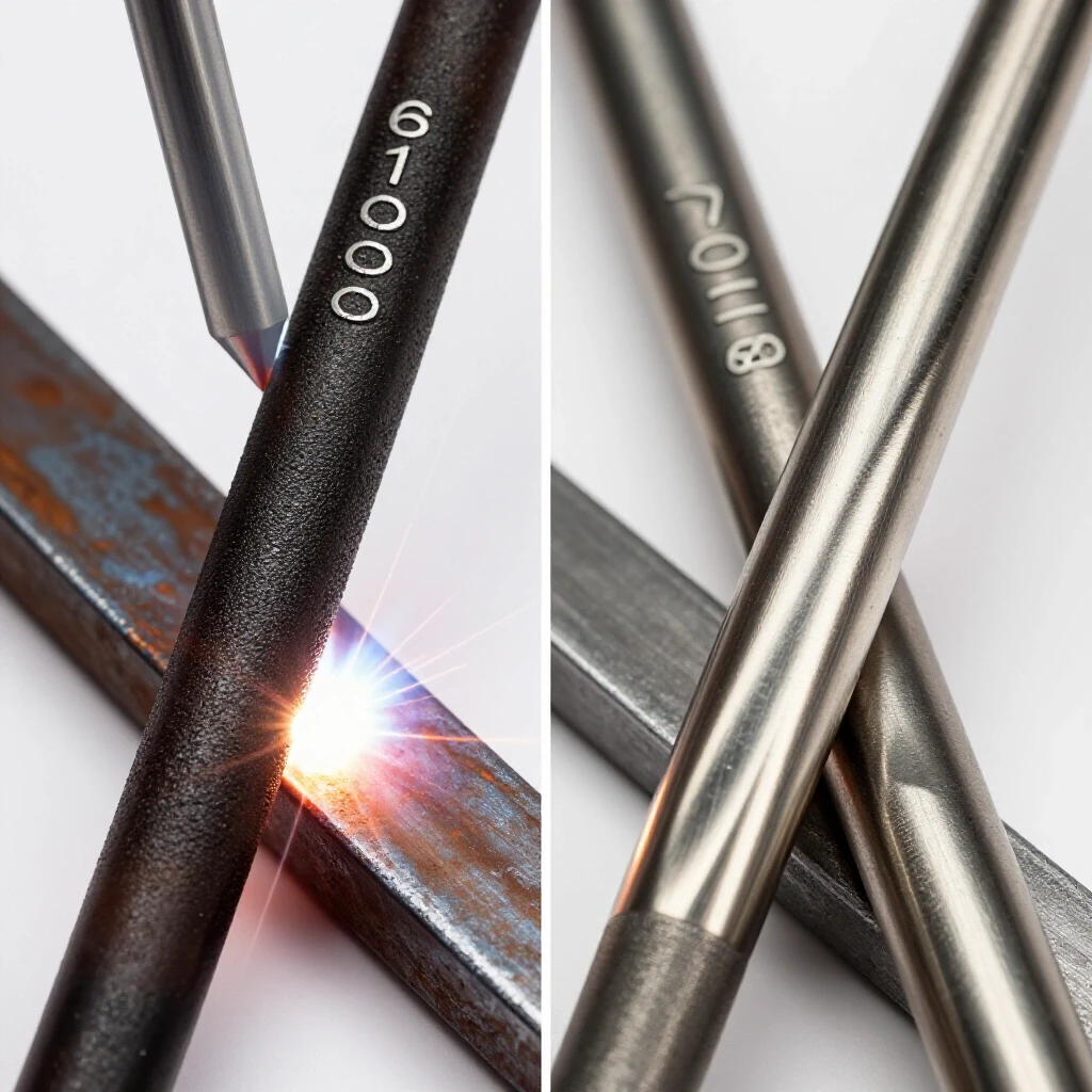
Understanding the difference between a deep-digging arc and a high-deposition fill is the first step in any metalworking diagnostic guide. If you don’t master this, you will find yourself chasing “electrical gremlins” that are actually just poor penetration. I approach every weld like a mechanical assembly—if the tolerances at the root aren’t right, the whole structure is compromised.
Establishing a Systematic Diagnostic Framework for Weld Integrity
A structured approach to identifying why a weld profile doesn’t meet requirements involves isolating variables like travel speed and rod angle. Before you change your machine settings, you must observe the behavior of the molten pool and the arc’s force against the steel.
When I walk into a shop to fix a recurring weld failure, I start by stripping the process back to the basics. I look at the material thickness—usually between 1/8 and 3/8 inches for most DIY and repair work—and the cleanliness of the surface. If a technician is struggling with a weld that won’t “take,” I check the electrode’s coating first.
The coating dictates the arc’s personality. One type uses cellulose to create a high-velocity gas shield that blasts away contaminants and pushes deep into the metal. The other uses iron powder and low-hydrogen minerals to create a heavy slag blanket that protects a slower, more controlled pool. If you swap these without adjusting your technique, you will encounter porosity or lack of fusion.
Building on this, I always use a “Variable Isolation Log.” This is a simple mental or written checklist where I change only one thing at a time. I might start by adjusting the arc length, then the travel speed, and finally the rod angle. By doing this, I can pinpoint exactly where the penetration is failing without introducing new errors.
Analyzing the Digging Action of Cellulose-Coated Electrodes
Understanding how high-cellulose coatings create deep-reaching arcs is essential for repairs on less-than-perfect surfaces. These rods are designed to operate on DC+ polarity, providing a forceful arc that can penetrate through rust, paint, and mill scale.
In my experience, the E6010 is the “diagnostic tool” of welding rods. If I am not sure how deep a crack goes, I use a 6010 to “ve-out” the area or run a root pass. The cellulose coating burns vigorously, creating a focused jet of plasma. This jet doesn’t just melt the surface; it physically displaces the molten metal to reach the bottom of the joint.
Interestingly, this aggressive action is exactly what you need for a root pass on a V-groove. I once consulted for a shop where their structural frames were cracking at the corners. They were using a rod that laid down a lot of metal but didn’t reach the back side of the joint. By switching to a cellulose-based rod for the first pass, they achieved full-depth fusion, which stopped the stress fractures immediately.
However, this deep penetration comes with a trade-off. The weld pool freezes very quickly, which requires a “whip-and-pause” technique. If your hand isn’t steady or if your welding table has excessive vibration—similar to tool chatter in a lathe—you will end up with an inconsistent bead. I always check the stability of the workpiece before starting a high-penetration pass.
Managing the Fill Rate and Bead Profile of Low-Hydrogen Rods
Iron-powder coatings prioritize metal deposition over depth, making them ideal for adding structural mass to a joint. These electrodes, like the E7018, produce a much calmer arc that is easier to control but lacks the “digging” power of cellulose rods.
When I transition from a root pass to a fill pass, I look for a rod that can bridge gaps and leave a smooth finish. The E7018 is the gold standard here. Its coating contains iron powder, which melts into the pool, increasing the amount of metal deposited per inch of weld. This results in a thick, protective slag that slows the cooling rate of the metal.
As a result, the weld is more ductile and less prone to cracking under vibration. In one case study involving a vibrating shaker screen at a local mill, we found that the welds were failing because they were too brittle. We diagnosed the issue as a combination of poor penetration in the root and a lack of fill in the cap. By using a 7018 for the final passes, we provided enough “meat” to the joint to dampen the harmonic vibrations of the machine.
One common mistake I see is trying to use these rods on dirty or rusty metal. Because the arc is less aggressive, it cannot burn through contaminants. Instead, the impurities get trapped under the slag, leading to troubleshooting weld porosity later. If you see “pinholes” in your 7018 bead, your first diagnostic step should be to check your base metal cleanliness.
| Factor | Cellulose-Coated (E6010) | Low-Hydrogen (E7018) |
|---|---|---|
| Primary Polarity | DC+ (Direct Current Electrode Positive) | AC or DC+ |
| Penetration Depth | Deep and Aggressive | Moderate and Controlled |
| Slag Characteristic | Thin, easy to remove | Heavy, glass-like |
| Metal Cleanliness | Tolerates rust/scale | Requires clean, bright metal |
| Typical Application | Root passes, tacking, dirty metal | Fill passes, capping, high-stress joints |
| Bead Appearance | Rough, distinct ripples | Smooth, uniform ripples |
Troubleshooting Root Pass Defects and Lack of Fusion
Identifying why the first pass fails to penetrate the back side of the joint involves checking the gap width and landing thickness. If the root of the weld is hollow, the entire structure is essentially a ticking time bomb of mechanical failure.
When I diagnose a “cold” root pass, I first measure the root opening with a set of calipers. For a standard 1/4-inch plate, I look for a gap of about 3/32 of an inch. If the gap is too tight, even a high-penetration rod like the 6010 won’t be able to reach the back side. Building on this, the “land”—the flat part at the bottom of your bevel—should be about 1/16 of an inch thick.
If the land is too thick, the arc won’t be able to consume it, leading to a “bridge” of weld metal that doesn’t actually fuse to the bottom. I’ve seen this happen in many DIY projects where the fabricator was afraid of “blowing through” the metal. In reality, blowing through occasionally is a sign that you have enough heat to ensure full penetration.
To isolate this issue, I perform a “test strip.” I take two pieces of scrap of the same thickness, set them up with the same gap, and run a pass. Then, I cut the piece in half and inspect the cross-section. This is the only way to verify that your penetration is reaching the target depth without relying on guesswork.
Diagnosing Porosity and Surface Contamination Issues
Tracking down the source of gas pockets and holes in the weld metal requires a systematic look at the environment and the consumables. Porosity is often a sign that the shielding gas—created by the rod’s coating—is being compromised.
In my years of metal fabrication fixes, I’ve found that porosity in 7018 welds is almost always caused by moisture in the coating or an arc length that is too long. If the arc is too long (greater than the diameter of the rod), the shielding gas disperses before it can protect the molten pool. This allows nitrogen and oxygen from the air to enter the weld, creating tiny bubbles.
For 6010 rods, porosity usually comes from moving too fast or using the wrong “whip” motion. If you don’t allow the gas shield to settle over the pool before moving forward, you leave the trailing edge of the weld exposed. Interestingly, 6010 rods actually need a small amount of moisture in their cellulose coating to work correctly, whereas 7018 rods must be kept bone-dry.
Welding Porosity Diagnosis Pathways: 1. Check Arc Length: Is the rod held within 1/8 inch of the plate? 2. Inspect Material: Is there oil, moisture, or heavy galvanization present? 3. Analyze Travel Speed: Are you outrunning the gas shield? 4. Examine Consumables: Has the 7018 been exposed to humidity for more than 4 hours?
Correcting Machine Misalignment and Arc Stability Problems
Fixing mechanical or electrical issues that cause arc wandering or inconsistent penetration is vital for maintaining a steady weld pool. Sometimes the problem isn’t the rod or the welder’s hand, but the machine’s electrical circuit.
I once spent three hours troubleshooting a “wandering arc” on a large fabrication table. The welder complained that the arc was being “blown” to the side, making it impossible to get deep penetration in the corner. This is a phenomenon known as magnetic arc blow. It happens when the magnetic field created by the welding current becomes unbalanced.
To fix this, I checked the ground clamp. It was attached to a painted leg of the table rather than the workpiece itself. This created a high-resistance path (measured at over 5 Ohms), which forced the current to find a messy way back to the machine. By moving the ground closer to the joint and ensuring a metal-to-metal connection, the arc stabilized immediately.
Another mechanical factor is the stability of your welding arm or jig. If your setup has “spindle backlash” or loose clamps, the vibrations from the shop floor can translate into your weld bead. I use a dial indicator to check for any movement in my jigs. If I see more than 0.005 inches of play, I know my weld consistency will suffer.
Why Tool Chatter and Vibration Affect Weld Penetration
While we often associate chatter with lathes and mills, vibrational harmonics play a massive role in manual welding. If the workpiece is resonating at a certain frequency, it can disrupt the surface tension of the molten pool.
When using a 6010 rod, you are essentially “pulsing” the heat into the metal. If your workpiece is clamped poorly and starts to vibrate due to the arc’s force, that vibration can cause the molten metal to eject from the pool—a phenomenon similar to “spatter” but more rhythmic. This leaves “valleys” in your bead that lack proper penetration.
To solve this, I look for “rigid harmonic vibrations.” I use a simple smartphone vibration spectrum analyzer app to see if the table is shaking. Often, just adding a heavy sandbag or a C-clamp to a long, thin plate will dampen the vibration. This stabilizes the pool, allowing the 6010 to dig a consistent trench and the 7018 to lay a flat, even cap.
Actionable Tracking Framework: The Weld Diagnostic Log
To avoid the frustration of “electrical gremlins” and recurring defects, I recommend keeping a log. This moves you away from random guesswork and toward a systematic diagnostic approach.
- Initial Observation: Note the bead shape. Is it “cold” (tall and narrow) or “hot” (flat and wide)?
- Material Check: Verify thickness and joint prep. Are the bevels at 30 degrees?
- Machine Calibration: Use a clamp-on ammeter to verify that your machine is actually putting out the 90 amps the dial claims. I’ve seen machines off by as much as 15%.
- Consumable Check: Ensure you are using DC+ for 6010 and the correct polarity for your specific 7018.
- Vibration Test: Tap the workpiece. If it “rings” like a bell, it needs better clamping to prevent pool disruption.
- Cross-Section Analysis: On critical repairs, weld a scrap piece first and cut it to verify the penetration depth.
Real-World Case Study: The Misaligned Flange
I was called to a shop where a 12-inch pipe flange was consistently failing a pressure test. The fabricators were using a 7018 for the whole job. They were getting beautiful beads, but the water was leaking right through the root of the weld.
My diagnosis was simple: the 7018 didn’t have the “bite” to fuse the heavy flange to the pipe wall at the very bottom of the groove. The slag from the 7018 was getting trapped in the tight corner, creating a “slag inclusion” that acted like a tiny tunnel for water.
We changed the procedure. We used a 1/8-inch 6010 for the root pass to ensure we “consumed” the edges of both the pipe and the flange. Once we had a solid, deep-penetrating base, we cleaned the thin slag and finished the job with 7018. The result was a leak-free joint. This taught the crew that “pretty” doesn’t always mean “penetrated.”
Conclusion: Mastering the Physics of the Arc
Troubleshooting fabrication issues is a game of elimination. By understanding that a cellulose rod is a high-pressure digging tool and a low-hydrogen rod is a high-volume filling tool, you can choose the right “weapon” for the job. Don’t let a “dirty” piece of steel or a vibrating table ruin your work.
Start by checking your mechanical baselines—your gaps, your lands, and your grounding. Then, move to your electrical variables, ensuring your amperage is true and your polarity is correct. If you follow this systematic path, you will stop guessing and start building with the confidence of a seasoned specialist.
Frequently Asked Questions
Why does my 6010 rod keep sticking to the metal?
This is usually caused by an amperage setting that is too low or an arc length that is too short. 6010 rods require a “tight” arc, but if you touch the metal, the fast-freezing pool will grab the rod. Increase your current by 5-10 amps or check if your ground clamp has high resistance.
Can I use a 7018 rod on a small 110V welder?
It is difficult. 7018 rods require a stable voltage to keep the iron-powder coating melting smoothly. Many small 110V machines struggle to maintain the “arc force” needed, leading to the rod “freezing” to the plate. For these machines, a 6011 (the AC version of 6010) often provides better results for penetration.
How do I know if I have “full penetration”?
The most reliable DIY method is the “visual back-side” check. If you are welding a butt joint, you should see a small “bead” or “heat tint” on the opposite side of the plate. If the back side looks untouched, you haven’t achieved full penetration.
Why is the slag on my 7018 so hard to remove?
Hard slag is often a sign of “undercut” or improper amperage. If the weld is too hot, the slag can bake into the edges of the metal. If the amperage is correct, 7018 slag should often peel up on its own or come off with a light tap of a chipping hammer.
What causes the “pinholes” at the start of my 7018 weld?
This is called “starting porosity.” It happens because the shielding gas hasn’t fully formed when you first strike the arc. To fix this, strike the arc about an inch ahead of where you want to start, then quickly move back to the start point and weld over the strike mark.
Does 6010 work on AC (Alternating Current)?
Generally, no. A true E6010 is designed for DC+ only. If you try to run it on AC, the arc will be unstable and will frequently extinguish. If you only have an AC machine, use an E6011 rod instead; it has a similar cellulose coating but is formulated for AC stability.
How thick can I weld with a single pass of 6010?
For reliable penetration, a single pass is usually limited to 1/8 to 3/16 inch steel. For anything thicker, such as 3/8 inch plate, you should bevel the edges and use a multi-pass technique: a 6010 root pass followed by 7018 fill passes.
Why is my weld bead wandering to one side?
This is likely magnetic arc blow. It happens when the magnetic field of the welding current gets bunched up, often near the ends of a plate or in deep corners. Try moving your ground clamp to the other side of the workpiece or wrapping your welding cable around the workpiece to create a counter-magnetic field.
What is the difference between “dig” and “fill”?
“Dig” refers to the arc’s ability to push into the base metal and melt it deeply (characteristic of 6010). “Fill” refers to the rod’s ability to deposit a large volume of metal to build up the joint (characteristic of 7018). You need “dig” for strength and “fill” for mass.
Can I weld over rust with 7018?
It is not recommended. 7018 is a “low-hydrogen” rod that requires clean metal. Rust contains moisture and oxygen, which will cause porosity and cracking in a 7018 weld. Always grind the metal to a bright finish before using 7018. If you can’t clean it, use a 6010 or 6011.
Why does my machine vibrate when I am welding?
If the machine itself is vibrating, it could be a cooling fan issue or an internal transformer vibration. However, if the workpiece is vibrating, it’s usually due to the “arc force” of a high-penetration rod. Ensure your work is clamped to a heavy, stable surface to prevent this from affecting your bead.
How do I stop the “pockmarks” on the surface of my 6010 weld?
These are often caused by a “whip” that is too long. If you pull the rod too far away from the pool during the “whip” motion, you lose the gas shield. Keep your whip short—no more than two electrode diameters—to maintain a clean surface.
(This article was written by one of our staff writers, Paul Whitaker. Visit our Meet the Team page to learn more about the author and their expertise.)