Calculate Voltage Drop on Welder Extension Cords (DIY Guide)
I have spent over 15 years chasing ghosts in fabrication shops. There is a specific kind of frustration that sets in when a machine that worked perfectly yesterday begins to stutter today. You check the consumables, you verify the gas flow, and you recalibrate the feed rates, yet the performance remains inconsistent. In my experience as a diagnostic specialist, the most elusive “electrical gremlins” often hide in the very cables feeding the equipment. When a machine draws high current through an undersized or overly long conductor, the resulting loss in electrical pressure can cripple sensitive electronics and lead to poor results that look like mechanical failures.
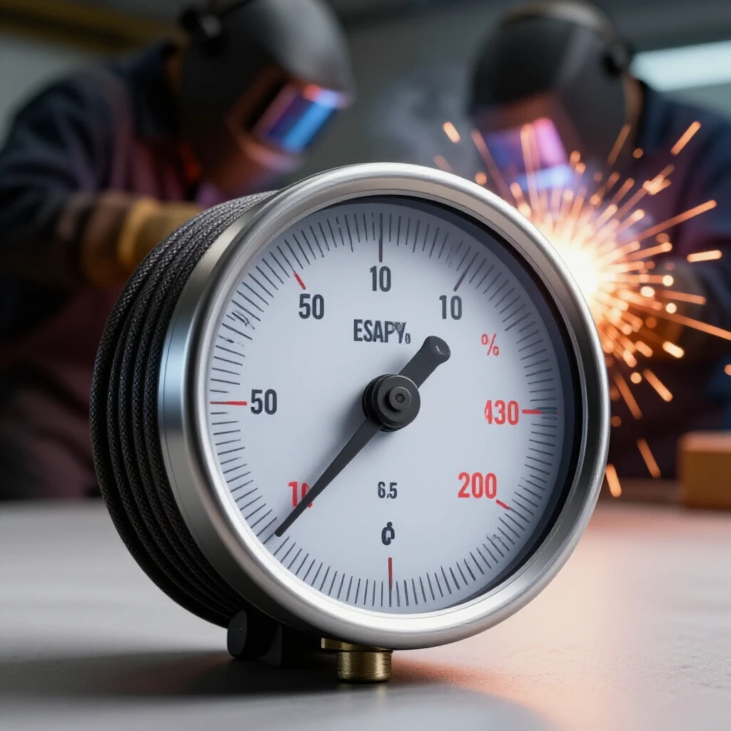
Systematic troubleshooting is about isolating variables until only the truth remains. I recall a project where a large CNC plasma table was losing its arc mid-cut. The operator was convinced it was a software bug or a faulty solenoid. After three hours of checking code and air lines, I hooked up a multimeter to the power input. We found that under full load, the voltage was plummeting by nearly 15 percent. The culprit was a 100-foot extension that simply couldn’t handle the demand. By understanding how to quantify this loss, you move from guessing to knowing.
Establishing a Diagnostic Framework for Power Consistency
A diagnostic framework is a structured method used to isolate electrical issues by comparing the source power to the power delivered at the machine terminal. This process involves measuring voltage under a “no-load” state and comparing it to measurements taken while the equipment is actively drawing current to identify hidden resistance.
When I walk into a shop to solve a performance issue, I start at the wall. You cannot diagnose a machine if you don’t know what the building is giving you. Many fabricators assume that a 240-volt outlet always provides 240 volts. In reality, that number fluctuates. If your base voltage is already on the low side, any further loss through a long cable will push the machine outside its operational tolerances.
I use a three-step observation phase: 1. Static Measurement: Check the voltage at the outlet with the machine off. 2. Active Measurement: Check the voltage at the machine’s power entry point while it is running. 3. Differential Analysis: Subtract the active voltage from the static voltage to find the total loss.
Building on this, you must realize that resistance is not static. As cables heat up, their ability to conduct electricity decreases, which increases the loss. This creates a feedback loop where a warm cable causes more loss, leading to more heat, and eventually, a machine shutdown or a blown board.
Quantifying Energy Loss Across Extended Conductors
Energy loss across a conductor, commonly known as voltage drop, is the reduction in electrical potential as current flows through the resistance of a wire. It is governed by Ohm’s Law and is directly proportional to the length of the cable and the amount of current being pulled by the load.
To solve these issues, you need to understand the math. You don’t need a degree in electrical engineering, but you do need to know how wire gauge and length interact. The resistance of a copper wire is a fixed physical property based on its cross-sectional area. A thinner wire (higher gauge number) has more resistance than a thicker wire.
Interestingly, the length of the cable doubles the resistance for every foot added. If you have a 50-foot cord, the electricity has to travel 50 feet to the machine and 50 feet back to the source. That’s 100 feet of resistance. If the machine is pulling 50 amps, even a small amount of resistance per foot can lead to a massive drop in delivered power.
Resistance Values for Common Shop Cables
| Wire Gauge (AWG) | Resistance (Ohms per 1,000 feet) | Max Recommended Amps (Continuous) |
|---|---|---|
| 12 | 1.588 | 20 |
| 10 | 0.998 | 30 |
| 8 | 0.628 | 40 |
| 6 | 0.395 | 55 |
| 4 | 0.248 | 70 |
As a result of these physical constants, a 6-gauge wire will lose significantly less energy over 100 feet than a 10-gauge wire. When I am troubleshooting a machine that displays “Low Voltage” errors, this table is the first thing I consult to see if the cord is even capable of the task.
The Impact of Under-Voltage on Fabrication Equipment
Operating machinery at a voltage below its design specification leads to increased heat in motors, erratic behavior in digital controllers, and a loss of torque or arc stability. This condition forces the machine to draw more current to compensate for the lower voltage, which can damage internal components over time.
I’ve seen many cases where tool chatter or poor surface finish on a lathe was actually caused by a power issue. If the motor doesn’t have enough “push” (voltage) to maintain a constant RPM under load, the spindle speed will fluctuate. These micro-fluctuations create resonant vibrations that look like a mechanical alignment problem but are actually electrical.
In welding applications, the power supply needs a stable input to maintain the arc. If the voltage drops too low, the transformer or inverter cannot compensate. This leads to a “cold” weld, where the metal doesn’t fuse properly, or excessive spatter. You might think your technique is off, but the machine is simply starving for fuel.
- Motor Overheating: Motors run hotter when voltage is low because they pull more amps to do the same work.
- Controller Resetting: Digital displays and PLCs may reboot or throw “Error 01” codes if voltage dips during a high-load start.
- Arc Instability: The arc may flutter or extinguish because the power supply cannot maintain the necessary ionization potential.
Calculating the Percentage of Power Loss
Calculating the percentage of power loss involves dividing the measured voltage drop by the source voltage and multiplying by 100. This metric allows a fabricator to determine if the power delivery system meets the industry-standard goal of keeping losses below 3 to 5 percent.
To perform this calculation in your shop, use the following formula: Percentage Drop = ((Source Volts – Load Volts) / Source Volts) x 100
For example, if your outlet provides 240 volts, but your machine only sees 220 volts while running, your drop is 20 volts. (20 / 240) x 100 = 8.33%.
In most industrial settings, a drop of more than 5% is considered problematic. If you are seeing 8% or 10%, you are effectively wasting power and risking your equipment. I always tell my clients that if they can’t get the drop under 3%, they should consider moving the machine closer to the panel or upgrading the wire size.
Systematic Testing for Resistance and Heat
Testing for resistance and heat involves using a digital multimeter to check for continuity and voltage differentials, alongside thermal imaging to identify “hot spots” in cables or connectors. These tools help locate specific points of high resistance that contribute to overall power loss in a system.
One of my favorite diagnostic tools is an infrared (IR) thermometer. Resistance creates heat. If you have a 50-foot cord and one specific spot or one plug end is significantly hotter than the rest of the cable, you’ve found a point of failure. It could be a loose wire inside the plug or a partial break in the copper strands from being stepped on or driven over.
Electrical Diagnostic Steps
- Inspect Connectors: Look for discoloration or “bluing” on the brass prongs of your plugs. This indicates extreme heat.
- Check Terminal Tightness: Open the machine’s power entry box and ensure the lugs are torqued to spec. Vibration often loosens these over time.
- Measure Voltage at the Breaker: Ensure the issue isn’t a loose connection at the main panel busbar.
- Load Test: Use a clamp-on ammeter to see exactly how many amps the machine is pulling. Often, machines pull more than the nameplate suggests during startup.
I once worked on a large hydraulic press that would trip its breaker randomly. By using a clamp meter, I discovered that the motor was pulling 20% more current than rated because the long, thin extension cord had dropped the voltage so much that the motor was struggling to turn the pump. We replaced the cord with a shorter, heavier version, and the “mechanical” problem vanished.
Mechanical Impacts of Under-Voltage Operations
Under-voltage operations can cause mechanical components like solenoids and contactors to chatter or fail to engage fully. This leads to increased wear on mechanical surfaces and can cause “back-EMF” faults that interfere with other nearby electronic equipment.
When a contactor (the heavy-duty relay that turns a machine on) doesn’t get enough voltage, the magnetic coil isn’t strong enough to hold the contacts closed firmly. They start to bounce or “chatter.” This creates micro-arcs that pit the silver faces of the contacts, eventually welding them shut or preventing them from conducting at all.
This isn’t just an electrical issue; it’s a reliability issue. If your machine’s cooling fan is running on low voltage, it’s spinning slower. This means the internal heat-sinks aren’t being cooled properly, which shortens the life of the entire unit. Every component in your machine is rated for a specific voltage range, usually +/- 10%. If you are consistently at the bottom of that range, you are living on borrowed time.
Advanced Diagnostic Math: Estimating Drop Before Buying
Advanced diagnostic math allows a fabricator to predict the performance of a power setup by using the circular mil area of a conductor and its resistivity constant. This proactive approach prevents the purchase of inadequate equipment and ensures that new shop layouts will support heavy machinery.
If you are planning to move a machine to the other side of the shop, don’t guess which cable you need. You can estimate the loss using this formula: VD = (2 x L x R x I) / 1000
- VD: Voltage Drop
- L: Length of the cord in feet (one way)
- R: Resistance of the wire (from the table above)
- I: Current in Amps
Let’s say you want to run a machine that pulls 40 Amps on a 100-foot, 8-gauge cord. L = 100, R = 0.628, I = 40. VD = (2 x 100 x 0.628 x 40) / 1000 VD = 5.024 Volts.
On a 240V circuit, a 5-volt drop is only about 2%. That is an excellent result. However, if you tried that same 100-foot run with a 12-gauge cord (R = 1.588): VD = (2 x 100 x 1.588 x 40) / 1000 VD = 12.7 Volts. That is over 5% and will likely cause issues during peak loads.
Troubleshooting Common Power-Related Machine Failures
Troubleshooting power-related machine failures involves identifying symptoms like “ghost” restarts, flickering displays, or inconsistent motor torque and linking them to inadequate power delivery. This systematic approach looks past the mechanical symptoms to find the electrical root cause.
In my repair logs, I’ve categorized several “phantom” issues that were solved simply by addressing the power delivery. One common one is the “Mid-Cycle Fault.” A machine starts fine, but as it works harder and gets hotter, it errors out. This is almost always due to the rising resistance in an undersized cable as it warms up.
Another is “Tool Chatter.” If you’re using a lathe or mill and you can’t get rid of a finish problem despite new inserts and rigid setups, check your voltage. If the motor is “hunting” for speed because the voltage is sagging, it will create a harmonic that ruins your finish.
Comparison of Power-Related Symptoms
| Symptom | Likely Mechanical Cause | Actual Electrical Root Cause |
|---|---|---|
| Excessive Spatter | Bad gas or dirty wire | Low voltage causing arc instability |
| Motor Stalling | Dull tool or heavy feed | Voltage drop reducing motor torque |
| Controller Rebooting | Software glitch | Voltage dip below logic threshold |
| Overheating Motor | Bad bearings | High amperage due to low voltage |
Building on these observations, the solution is rarely to “fix” the machine. The solution is to fix the path the power takes to get to the machine. I always recommend keeping extension cords as short as humanly possible. If you must go long, go heavy.
Practical Steps for Resolving Power Delivery Issues
Resolving power delivery issues requires a combination of shortening cable runs, increasing conductor thickness, and ensuring all connection points are clean and secure. These steps aim to minimize resistance and ensure the machine receives the full potential of the source power.
If you find that your setup is causing a significant drop, here is my checklist for a permanent repair:
- Shorten the Run: Can the machine be moved closer to the outlet? Even 10 feet makes a difference.
- Increase Gauge: If you are using a 12-gauge cord for a 20-amp load over 50 feet, move up to a 10-gauge cord.
- Check the “Hidden” Cord: Don’t forget the wire inside the wall. If the outlet is 100 feet from the panel, you already have a drop before you even plug in your extension.
- Clean Connections: Use an electrical contact cleaner on your plugs. Oxidation creates resistance, and resistance creates voltage drop.
- Dedicated Circuits: Ensure no other machines are running on the same circuit. You might get away with a thin cord for a small drill, but for a machine that shapes metal, you need every volt the utility company provides.
Actionable Tracking Framework: The Power Log
A power log is a diagnostic record where a fabricator documents voltage readings at different times of day and under various load conditions. This data helps identify intermittent power issues caused by external factors, such as shop-wide demand or grid fluctuations.
I recommend keeping a simple log for your most sensitive machines. This helps you spot trends. If a machine only acts up on Tuesday afternoons, and your log shows the building voltage is 5V lower on Tuesdays because the shop next door is running their heat-treat oven, you’ve found your answer.
- Date/Time: When did the fault occur?
- Source Voltage: What is the outlet providing?
- Load Voltage: What is the machine seeing?
- Amperage: How many amps is the machine pulling?
- Ambient Temp: Is the shop 100 degrees or 60 degrees?
This data-driven approach removes the “magic” from troubleshooting. It turns a frustrating afternoon into a simple math problem. When you can show a landlord or an electrician a log of voltage drops, they are much more likely to take your concerns seriously.
Summary of Diagnostic Benchmarks
To maintain a healthy shop environment, you should aim for specific benchmarks in your power delivery. These numbers are based on standard mechanical engineering practices and will ensure your equipment runs as intended by the manufacturer.
- Maximum Voltage Drop: 3% for sensitive electronics, 5% for general machinery.
- Maximum Temperature Rise: A cord should never feel “hot” to the touch (usually no more than 30°F above ambient).
- Voltage Balance: On three-phase equipment, the voltage between any two legs should be within 2% of each other.
- Connection Resistance: Ideally, you want less than 0.1 Ohms of resistance across any single plug or connector.
By following these guidelines and performing regular checks, you can avoid the downtime that comes with power-related failures. Troubleshooting isn’t about having a “gut feeling”; it’s about having a meter, a formula, and the patience to follow the wire back to the source.
Frequently Asked Questions
Why does my machine only throw errors when I’m using a long cord?
When you use a long cord, the electricity has to fight through more resistance. This causes the voltage to drop by the time it reaches the machine. If the voltage falls below the machine’s minimum requirement, the digital brain of the machine will shut it down to prevent damage to the motors.
Can a voltage drop cause my tools to vibrate or chatter?
Yes. If an electric motor doesn’t receive steady voltage, its torque output fluctuates. These tiny “pulses” in power can translate into vibrations in the spindle or drive system. This often looks like a mechanical alignment issue, but it is actually the motor struggling to stay at a constant speed.
How do I know if my extension cord is thick enough?
The best way is to measure the voltage at the machine while it is running. If the voltage is more than 5% lower than the voltage at the wall outlet, your cord is too thin or too long. You can also check if the cord feels warm after 10 minutes of use; warmth is a sign of wasted energy and high resistance.
Is it better to have one long cord or two shorter ones plugged together?
One long cord is always better. Every time you have a plug-and-socket connection, you add a point of resistance. Two 50-foot cords plugged together will almost always have a higher voltage drop than a single 100-foot cord of the same gauge because the connection in the middle isn’t as efficient as a continuous wire.
Will low voltage damage my machine permanently?
It can. Low voltage causes motors to run much hotter than they were designed for. Over time, this heat breaks down the insulation on the motor windings, leading to a short circuit and total motor failure. It can also burn out the contacts in your switches and relays due to “chattering.”
Does the temperature of my shop affect power loss?
Yes. Copper’s resistance increases as it gets hotter. If your shop is very hot, or if the cord is sitting in direct sunlight, it will have more resistance than it would in a cool environment. This means your voltage drop will actually get worse on hot days or during long periods of heavy use.
Can I use a regular multimeter to check for these issues?
Absolutely. A standard digital multimeter is your best friend here. Set it to AC Volts and measure the source at the wall, then measure the input at the machine. Just be very careful when measuring live circuits, and ensure your meter is rated for the voltage you are testing (usually CAT III for shop power).
What is the “2% rule” for three-phase power?
In three-phase systems, you want the voltage between all three legs (L1-L2, L2-L3, L1-L3) to be almost identical. If one leg has a significantly higher voltage drop than the others (more than 2% difference), it causes the motor to vibrate internally and lose efficiency. This is often caused by a loose connection on just one wire in the cord.
Why do some people say to uncoil the cord before using it?
When a cord is coiled up and carrying a heavy load, it generates heat. Because the coils are touching each other, the heat can’t escape. This makes the wire even hotter, which increases resistance and voltage drop. In extreme cases, the insulation can melt, causing a fire or a short circuit.
How does voltage drop affect my weld quality?
A welding power supply needs a specific amount of “pressure” to keep the arc stable. If the voltage drops, the arc may become “soft” or flutter. This leads to poor penetration and a lack of fusion. You might find yourself turning up the settings on the machine to compensate, but you’re really just fighting the resistance in your cord.
(This article was written by one of our staff writers, Paul Whitaker. Visit our Meet the Team page to learn more about the author and their expertise.)