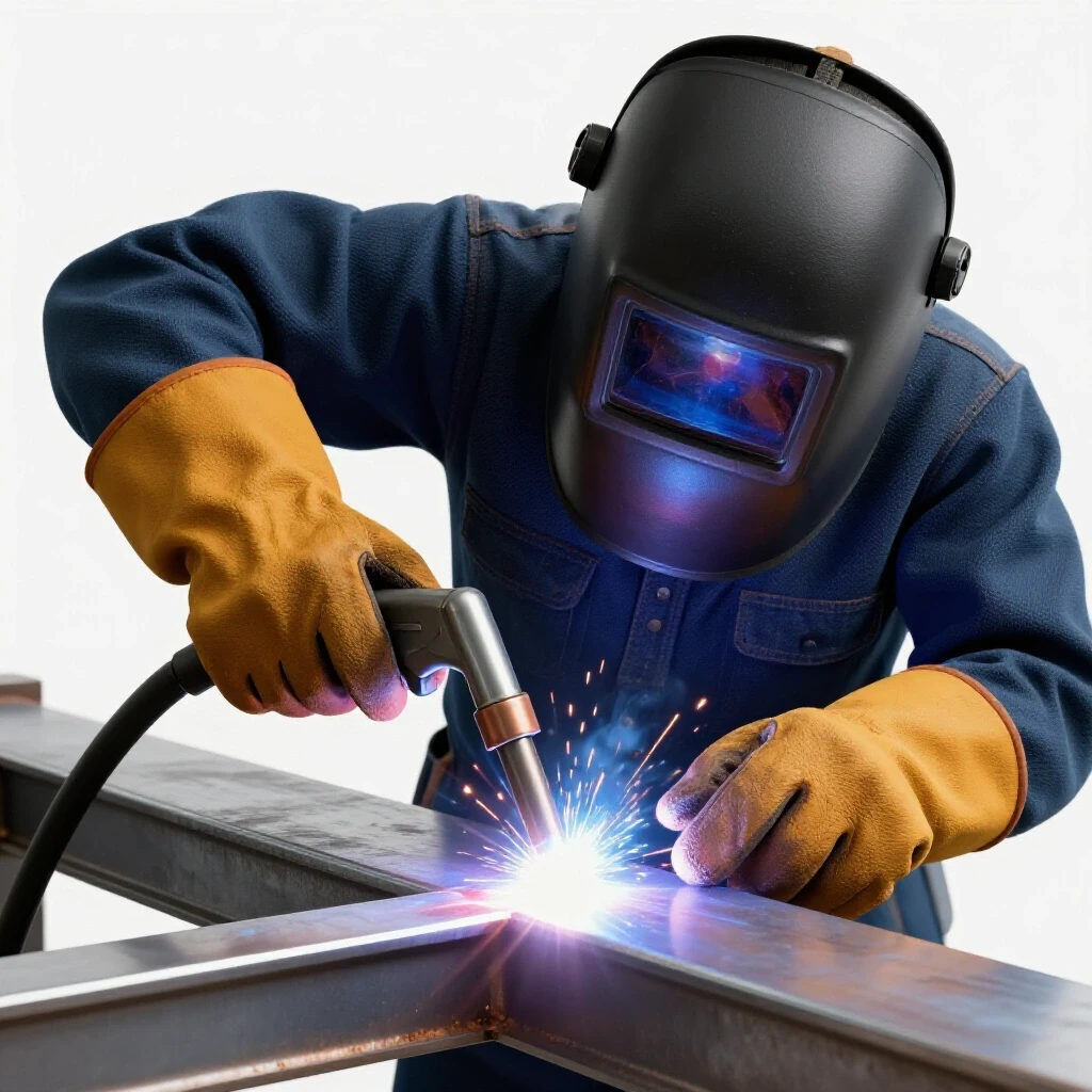
Choose Heavy Duty Welding Clamps That Do Not Slip (Tips)
I remember standing over a large structural frame ten years ago, watching a 1/8-inch gap open up in real-time as I laid a heavy root pass. I had used every tool in my kit to align the beams, but as the heat built up, the metal began to move. The issue wasn’t my weld sequence or the heat input; it was a subtle failure in the mechanical grip holding the assembly together. The workpieces were shifting just enough to ruin the tolerances, leading to hours of grinding and rework.
In my 18 years as a millwright and diagnostic specialist, I have learned that the most frustrating problems often stem from the smallest points of contact. When a workpiece slips, it doesn’t just ruin the alignment. It can introduce tool chatter during machining, cause grounding issues that lead to welding porosity, and create safety hazards. Mastering the selection of reliable workholding tools is a core skill for any fabricator who wants to stop guessing and start producing consistent, high-quality results.
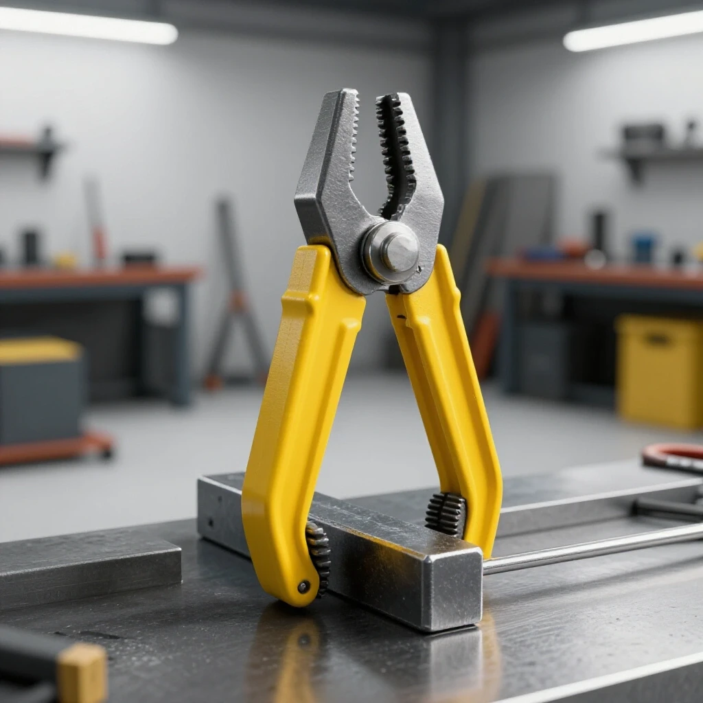
Mastering Mechanical Stability in Heavy-Duty Fabrication
Mechanical stability refers to the ability of a fixture to maintain the exact position of a workpiece against external forces like thermal expansion, gravity, and tool pressure. Achieving this requires a deep understanding of friction, leverage, and material science. Without a stable foundation, even the most precise measurements will fail during the actual fabrication process.
When I approach a new project, I start by evaluating the forces that will act on the material. If I am welding a heavy plate, the primary force is thermal stress. If I am drilling or milling, the primary force is the torque and vibration from the machine spindle. I look for tools that offer a high “mechanical advantage,” which is the ratio of the force produced by the tool to the force applied to it.
A common mistake I see is using a tool that is physically too small for the job. If a clamp is flexing under its own pressure, it has already lost its ability to resist the movement of the workpiece. I check for “deflection” by applying a dial indicator to the tool body while tightening it. If I see more than 0.005 inches of movement in the tool itself, I know I need a heavier-duty option with a larger cross-section or a more rigid alloy construction.
Analyzing Jaw Geometry for Maximum Friction
Jaw geometry involves the shape, surface texture, and alignment of the clamping faces that contact the metal. Proper geometry ensures that the force is distributed evenly and that the tool “bites” into the surface to prevent lateral sliding. This is the first line of defense against workpiece drift in high-torque environments.
I categorize jaw types into three main groups: serrated, smooth, and pivoting. Serrated jaws are my go-to for raw structural steel. The teeth create small points of high pressure that physically lock into the mill scale. However, if I am working on finished stainless steel or aluminum, those same teeth can cause “stress risers,” which are small indentations that can lead to cracks under load.
For finished surfaces, I look for pivoting pads. These pads allow the tool to adjust to the angle of the workpiece, ensuring full surface contact even if the two pieces aren’t perfectly parallel. I often use a “bluing agent” or simple chalk to test contact area. I coat the jaw, tighten it, and then release it to see how much of the pattern transferred to the metal. If I only see contact on one edge, the tool is likely to slip once the vibration starts.
Evaluating Surface Hardness and Material Compatibility
Surface hardness is measured on the Rockwell C scale (HRC) and determines how well a tool can resist wear and deformation. If the jaw material is softer than the workpiece, the teeth will flatten out over time, leading to a loss of grip. Conversely, if the jaw is too brittle, it can chip or shatter under high impact.
I prefer tools with jaws hardened to at least 45-50 HRC for general fabrication. This provides a good balance between toughness and wear resistance. When troubleshooting a slip, I always inspect the “peaks” of the serrations. If they look shiny or rounded, the tool has reached the end of its service life or was used on material that was too hard, such as AR400 wear plate.
Resolving Tool Chatter and Harmonic Vibrations
Tool chatter is a resonant vibration that occurs when the cutting tool and the workpiece are not held rigidly enough, causing the tool to “bounce” across the surface. This leaves a wavy finish and can destroy carbide inserts in seconds. Eliminating chatter requires increasing the damping and stiffness of the entire setup.
When I hear that high-pitched squeal during a machining operation, I don’t just slow down the feed rate. I look at the workholding. Vibration often stems from a “cantilever effect,” where the metal is held far away from the point of the cut. I use a smartphone vibration spectrum analyzer app to identify the frequency of the chatter. This helps me determine if the vibration is coming from the machine spindle or the workpiece itself.
To fix this, I move my high-pressure locking tools as close to the cut as possible. I also look for tools with “dampening” properties, such as those made from ductile iron or those with heavy copper-plated screws. Copper is softer than steel and can help absorb some of the high-frequency harmonics that lead to chatter.
Table 1: Stability Factors in High-Load Workholding
| Factor | Metric/Value | Impact on Fabrication |
|---|---|---|
| Clamping Force | 1,000 – 5,000+ lbs | Prevents movement under heavy thermal load or torque. |
| Jaw Hardness | 45 – 55 HRC | Ensures teeth don’t flatten when gripping hard alloys. |
| Screw Pitch | 10 – 12 TPI | Provides fine control over pressure and prevents “back-off.” |
| Throat Depth | 2 – 12 inches | Determines how far onto the material the tool can reach. |
| Deflection Limit | < 0.005 inches | Ensures the tool doesn’t flex and lose its grip. |
Diagnosing Weld Porosity and Alignment Issues
Weld porosity is a defect characterized by small holes or “pits” in the weld bead, usually caused by trapped gas or contamination. While many blame the shielding gas, I often find the root cause is a poor electrical ground. If a clamp is slipping or has a dirty contact point, it creates resistance, leading to an unstable arc and “arc blow.”
When I troubleshoot porosity, I use a multimeter to check the resistance (Ohms) between the work lead and the actual workpiece. If I see anything higher than 0.2 Ohms, I know my connection is weak. A high-quality locking tool with a dedicated copper grounding point can eliminate this variable. It ensures that the current has a direct, low-resistance path, which stabilizes the arc and reduces spatter.
Alignment issues, on the other hand, are often “creeping” problems. As you weld one side of a joint, the metal shrinks and pulls. If your workholding tools aren’t rated for high loads, they will “walk” along the surface. I track this by using a digital dial indicator to monitor the gap. If the gap changes by more than 0.010 inches during the first pass, I stop and re-evaluate my clamping strategy.
Table 2: Weld Defect Isolation Pathway
| Observed Issue | Potential Root Cause | Workholding Diagnostic Step |
|---|---|---|
| Intermittent Arc | High resistance at ground | Clean jaw faces; check for 0.2 Ohms or less. |
| Porosity at Start | Contaminated ground path | Ensure clamp is biting through mill scale to clean metal. |
| Dimensional Warp | Insufficient clamping force | Measure deflection; upgrade to high-PSI locking tools. |
| Arc Blow | Magnetic field buildup | Move grounding clamp closer to the weld zone. |
Troubleshooting Electrical Grounding via Clamping Points
Electrical grounding in welding is the process of creating a safe, low-resistance return path for the welding current. A failure in this path can cause the welder to “hunt” for voltage, leading to poor penetration and erratic beads. The clamp is the most critical link in this chain.
I always look for tools that have a “large surface area” contact pad for grounding. Small, spring-loaded clips are fine for light hobby work, but for heavy-duty fabrication, they are a liability. I prefer screw-type or locking-plier style tools that can be tightened until they are physically impossible to move by hand. This pressure breaks through the thin layer of oxidation that forms on steel and aluminum.
If I’m working on a rotating fixture, I use a specialized rotary ground. But for stationary work, I make sure the clamp is attached to a clean, shiny spot on the metal. I often use a flap disc to prep a 2-inch square area specifically for the grounding tool. This simple step has solved more “ghost” electrical problems than almost any other diagnostic trick in my bag.
Systematic Selection of High-Force Locking Tools
Selecting the right tool for a specific job involves a process of elimination based on the material, the process, and the required precision. I don’t just grab the first tool I see; I follow a mental checklist to ensure the tool is up to the task.
- Identify the Load: Is the force coming from heat, vibration, or weight?
- Check Material Compatibility: Will serrated jaws damage the surface?
- Evaluate Access: Do I have enough “throat depth” to reach the center of the plate?
- Confirm Grounding Needs: Does this tool need to carry 300+ amps of current?
- Test for Deflection: Does the tool body stay rigid when fully tightened?
I once worked on a project involving large aluminum tanks. We were getting consistent cracking in the heat-affected zone (HAZ). After a week of testing gas and wire, I realized the clamps were too tight and too rigid. As the aluminum tried to expand, the clamps held it so firmly that the metal had to crack to relieve the stress. We switched to tools with “pressure-limiting” features, and the cracking stopped immediately. This taught me that “tighter” isn’t always “better”—”consistent” is what matters.
Heat Resistance and Material Thermal Expansion
Thermal expansion is the tendency of matter to change its shape, area, and volume in response to a change in temperature. In welding, this is a massive force. A 10-foot steel beam can grow by nearly 1/8 inch when heated to welding temperatures. If your workholding tools can’t handle this expansion, they will either slip or bend.
I look for tools with “acme threads” on the adjustment screws. Acme threads are square-shaped and much more resistant to binding when they get hot. I also apply a high-temperature anti-seize lubricant to the threads. This prevents “galling,” where the metal threads weld themselves together under high heat and pressure. If a tool becomes difficult to turn after one weld, it’s a sign that the heat is causing the screw to expand faster than the body.
Case Study: Isolating a 0.030-inch Alignment Error
A few years ago, I was called into a shop that was building precision baseplates for industrial pumps. They were using heavy-duty C-clamps, but every plate was coming off the table with a 0.030-inch twist. This was outside the 0.005-inch tolerance required for the pump mounts.
We started by checking the table for flatness using a machinist’s straightedge. The table was perfect. Next, we checked the clamps. Under a load of approximately 1,500 lbs, we found that the frames of the clamps were bowing. As the weld cooled and pulled the metal, the bowed clamps acted like springs, allowing the plate to warp.
We replaced the standard C-clamps with “bridge-style” locking tools that had a much thicker spine. We also added “leveling feet” to the setup to support the plate from underneath. By switching to a tool that didn’t deflect under the thermal load, we brought the twist down to 0.003 inches, well within the spec. The lesson here was that the “heavy-duty” label on a tool is meaningless if it can’t maintain its geometry under real-world loads.
Actionable Tracking Framework: The Workholding Audit
To ensure my shop stays efficient, I perform a “workholding audit” every six months. This keeps my tools in top shape and prevents the kind of “creeping failures” that lead to downtime.
- Thread Inspection: Check for flattened or stripped threads. Lubricate with copper-based anti-seize.
- Jaw Integrity: Use a magnifying glass to check for rounded teeth or cracked pads.
- Pivot Point Check: Ensure all pins and pivots move freely without excessive “slop” or backlash.
- Spring Tension: On locking-plier styles, ensure the internal springs still provide snappy engagement.
- Grounding Path: Clean any copper contact points with a wire brush to remove oxidation.
By keeping a log of which tools fail and why, I can make better purchasing decisions in the future. If I see a certain style of tool consistently slipping on round tubing, I know I need to invest in “V-pad” adapters or specialized pipe clamps.
Practical Benchmarks for Shop Success
When you are in the middle of a job, you need quick ways to know if your setup is solid. I use these benchmarks to verify my workholding before I ever strike an arc or start a spindle.
- The “Hammer Tap” Test: Tap the workpiece with a dead-blow hammer. It should sound “dead” or solid. If it rings or vibrates, your clamping force is insufficient or poorly placed.
- The “0.002” Rule: Try to slide a 0.002-inch feeler gauge between the clamp jaw and the workpiece. If it goes in, you don’t have full surface contact.
- The Torque Feel: A high-quality screw-type tool should feel smooth as you tighten it. If it feels “gritty,” there is debris in the threads that will lead to a false sense of tightness.
- Voltage Drop Limit: When welding, the voltage drop between the machine and the workpiece should be less than 1-2 volts. Any more indicates a poor clamp connection.
These small checks take seconds but can save hours of troubleshooting later. In fabrication, the goal is to eliminate variables. A secure, non-slip grip is one of the easiest variables to control if you have the right tools and a systematic approach.
Frequently Asked Questions
Why do my clamps keep sliding off even when I tighten them as hard as I can? This usually happens because of “jaw deflection” or “surface mismatch.” If the tool body is flexing, the jaws are no longer parallel to the workpiece, causing them to squeeze the metal “out” like a bar of soap. Check for tool flex and ensure you are using jaws appropriate for the material (serrated for mill scale, smooth for finished plate).
How can I tell if a clamp is truly “heavy-duty” before I buy it? Look at the spine thickness and the screw diameter. A true heavy-duty tool will have a forged or thick-plate steel body and an acme-threaded screw. Check the “clamping force” rating; industrial-grade tools should be rated for at least 2,000 to 4,000 lbs of pressure.
What is the best way to prevent weld spatter from ruining my tool threads? Use tools with copper-plated screws or black oxide finishes. Copper naturally resists spatter adhesion. Additionally, always keep the threads retracted or covered when welding nearby, and use a dedicated “spatter guard” spray if the tool is in the direct line of fire.
Can a clamp cause welding porosity? Yes. If the clamp is your primary grounding point and it has a loose or dirty connection, it creates electrical resistance. This causes an unstable arc and can pull atmospheric gases into the weld pool, resulting in porosity. Always ensure a clean, metal-to-metal contact.
How do I stop my workpiece from “walking” during a long weld? This is caused by thermal expansion. You need to use tools with high lateral resistance (serrated jaws) and place them in a way that “boxes in” the material. Using a “tack and check” method alongside high-pressure locking tools is the most effective way to manage this.
Should I use copper or steel pads for aluminum fabrication? Copper pads are excellent for aluminum because they are softer and won’t mar the surface, but they also act as a heat sink. If you are struggling with “cold starts” on your welds, the copper might be pulling too much heat away. In that case, use stainless steel pads.
What does “HRC” mean in the context of tool jaws? HRC stands for Rockwell Hardness Scale C. It measures the indentation resistance of the metal. For welding tools, a jaw with an HRC of 45-55 is ideal—it’s hard enough to stay sharp but tough enough not to shatter under the impact of a hammer.
How often should I lubricate my screw-type clamps? In a high-production shop, I recommend a light application of high-temp anti-seize every week. If you notice the screw getting hot or “binding,” lubricate it immediately. This prevents galling and ensures you are getting true clamping pressure rather than just fighting thread friction.
Why is my machining finish “wavy” even though I have three clamps on the part? You likely have a “harmonic vibration” issue. The clamps may be tight, but they might be placed at “nodes” that allow the center of the part to vibrate. Try moving the clamps to irregular intervals or adding a dampening weight to the workpiece to break up the vibration frequency.
Is there a difference between “clamping force” and “holding capacity”? Yes. Clamping force is the amount of pressure the tool can actively apply to the workpiece. Holding capacity is the amount of external force the tool can resist before it fails or slips. For heavy fabrication, you need high ratings in both categories.
By focusing on these systematic diagnostic steps and choosing the right mechanical solutions, you can eliminate the “gremlins” that haunt many fabrication shops. It’s not about working harder; it’s about ensuring that once you set a piece of metal, it stays exactly where you put it.
(This article was written by one of our staff writers, Paul Whitaker. Visit our Meet the Team page to learn more about the author and their expertise.)