Designing Weld Joints for Standard Gas Lenses (DIY Guide)
I have spent eighteen years in fabrication shops, and if there is one thing I have learned, it is that the most frustrating problems are the ones you cannot see. You can have the best TIG welder on the market and a brand-new tungsten, but if your weld looks like a piece of burnt toast, you are likely fighting a battle with gas coverage. Many fabricators switch to a gas lens expecting it to solve every porosity issue, only to find that their joint design is actually working against the physics of the shielding gas. When a weld fails, I do not guess; I look at the variables, isolate the mechanical faults, and rebuild the process from the ground up.
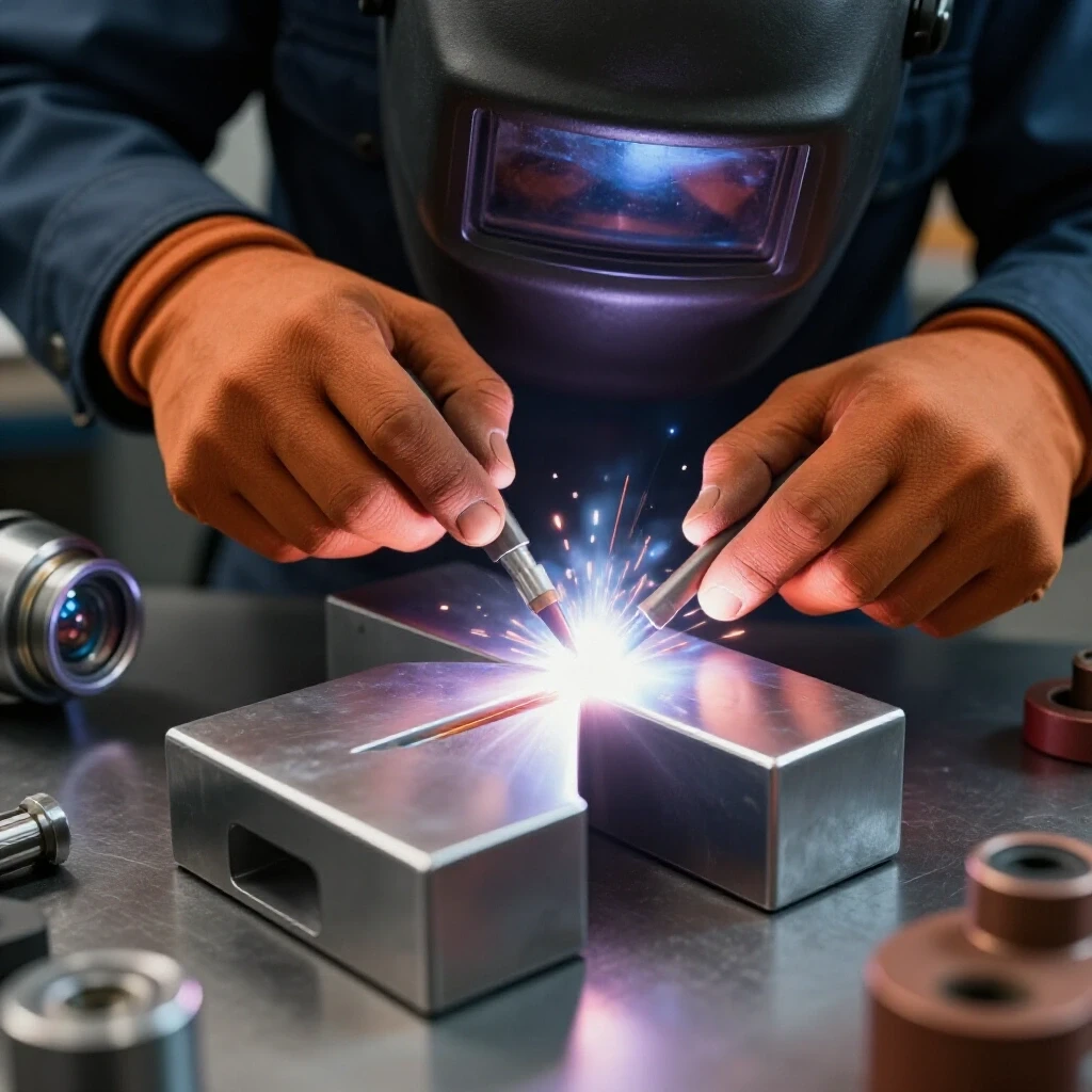
A gas lens is designed to create laminar flow, which is a smooth, straight stream of argon that protects the molten puddle. However, if the joint geometry is poorly planned, that smooth air can hit a sharp corner, swirl into a turbulent mess, and pull oxygen right into your weld. Troubleshooting weld porosity requires a deep dive into how we prep our edges and align our parts. In my experience, most “gas issues” are actually “geometry issues.” We are going to break down how to design your work to let your equipment perform exactly how it was engineered to.
Establishing a Systematic Framework for Gas Coverage
This diagnostic framework focuses on isolating the physical variables that disrupt the protective gas envelope during TIG welding. By treating gas flow as a fluid dynamic problem, we can identify whether a defect stems from the equipment, the environment, or the physical shape of the metal joint.
When I walk into a shop to fix a “bad welder,” the first thing I do is look at the workspace. Is there a breeze? Is the torch angle too steep? Once those are cleared, I look at the joint itself. A standard gas lens works by using a series of fine mesh screens to straighten the gas. If your joint has a massive gap or an awkward overhang, you are creating a low-pressure zone that sucks in atmospheric contamination.
I approach every weld as a three-part system: the delivery (the torch and lens), the environment (the shop air), and the target (the joint). If the delivery is perfect but the target is shaped like a scoop, you will get turbulence every time. I have seen guys crank their flow meters up to 40 CFH (cubic feet per hour) trying to fix porosity, not realizing that the high pressure is actually making the turbulence worse. The goal is a steady, gentle “blanket” of gas, not a high-pressure blast.
Why Joint Geometry Dictates Gas Shielding Efficiency
Joint geometry refers to the physical shape and angle where two pieces of metal meet. This structure determines whether the shielding gas remains in a stable, laminar state or becomes turbulent, which directly impacts the purity and strength of the finished weld.
Think of shielding gas like water coming out of a garden hose. If you aim it at a flat wall, it spreads out evenly. If you aim it into a sharp internal corner, it splashes back at you. In welding, that “splash” is turbulence, and it brings nitrogen and oxygen into your puddle. I have found that butt joints are the easiest to shield because there are no vertical walls to deflect the gas. Conversely, deep V-grooves or tight inside corners are the most difficult.
When I am designing a setup for a critical part, I consider the “escape path” for the gas. If the gas has nowhere to go, it will swirl. This is why edge preparation is so vital. If you have a 90-degree corner, you might need to increase your tungsten stick-out to get the lens closer to the root, but you must balance this against the risk of losing the gas envelope entirely.
- Butt Joints: Offer the most stable gas environment.
- Lap Joints: Create a “step” that can cause gas to roll over the edge.
- Corner Joints: Can act as a pocket that traps gas, but also creates “bounce back.”
- T-Joints: The most common source of turbulence due to the 90-degree intersection.
| Joint Type | Turbulence Risk | Recommended Flow (CFH) | Ideal Tungsten Stick-out |
|---|---|---|---|
| Flat Butt Joint | Low | 12-15 | 2x Diameter |
| Outside Corner | Medium | 15-18 | 1.5x Diameter |
| Inside T-Joint | High | 15-20 | 3x Diameter |
| Lap Joint | Medium | 12-15 | 2x Diameter |
Troubleshooting Weld Porosity in Tight Fillets
Fillet welds occur at the intersection of two perpendicular surfaces and are notorious for trapping air or causing gas deflection. Solving porosity in these joints requires adjusting the torch angle and the mechanical fit-up to ensure the gas lens can reach the root of the weld.
I remember a job involving 304 stainless steel frames where the welder was getting consistent porosity in every corner. He thought his gas lens was clogged. We took the lens apart, and it was clean. The issue was his torch angle. He was pointing the torch too far into the corner at a 45-degree angle, which caused the gas to hit the root and “mushroom” back toward the nozzle. This created a venturi effect, pulling in air from the sides.
We fixed it by slightly widening the fit-up and changing the technique to a more “push” oriented angle. By allowing a tiny 0.015-inch gap at the root, the gas had a place to go, which stabilized the arc. It seems counterintuitive to leave a gap to fix a gas issue, but sometimes you need to give the pressure a relief valve.
Identifying Gas Bounce-Back
Gas bounce-back happens when the volume of argon exiting the lens is too high for the space it is entering. If you are welding in a tight “U” channel, the gas fills the channel and then spills out the top, creating eddies. If you see black soot or “peppery” spots in your weld, you are likely seeing the results of this turbulence.
Optimizing Stick-Out for Fillets
Using a gas lens allows for a longer tungsten stick-out than a standard collet body. In a tight fillet, I usually extend the tungsten about 1/2 inch to 3/4 inch. This lets me keep the nozzle far enough away to avoid blocking my view while still keeping the laminar stream focused on the puddle. If the stick-out is too short, the large diameter of the gas lens nozzle can actually block the gas from reaching the very bottom of the joint.
Edge Preparation and Mechanical Clearances
Edge preparation involves the mechanical cleaning and shaping of the metal surfaces before welding. Proper clearances and clean edges ensure that the gas lens can provide a consistent shield without being hindered by surface contaminants or irregular gaps.
You cannot troubleshoot a gas issue on dirty metal. I have a strict rule in my shop: if the metal isn’t bright and shiny, we don’t weld it. When you are using a gas lens, the flow is so precise that any bit of mill scale, oil, or rust can disrupt the gas path. Contaminants can outgas when heated, creating bubbles that look like gas coverage issues but are actually metallurgical failures.
For aluminum, I use a dedicated stainless steel brush that has never touched carbon steel. For stainless, I use acetone and lint-free wipes. If you leave a burr on the edge of your metal from a cold saw or a grinder, that tiny sliver of metal can cause a “split” in your gas flow. It sounds like overkill, but at the microscopic level, that burr is a mountain that creates a wake in the argon stream.
- Mechanical Cleaning: Use a flap disc or dedicated wire brush to remove all oxides.
- Chemical Cleaning: Wipe down with a solvent like acetone to remove oils.
- Deburring: Ensure all edges are smooth to prevent gas flow disruption.
- Beveling: For material over 1/8 inch, a 30-degree bevel helps the gas reach the root.
Fit-Up Precision and Alignment Benchmarks
Fit-up precision refers to the accuracy with which two pieces of metal are positioned and held before welding. Maintaining tight tolerances—typically within 0.005 to 0.020 inches—prevents air pockets and ensures the gas lens maintains a consistent protective environment.
In my years of fixing structural alignment faults, I have found that a “loose” fit-up is the enemy of a clean weld. If your parts are not clamped tightly, they will warp as soon as you apply heat. When the metal warps, the joint opens up. That opening acts like a vacuum, pulling air from the backside of the weld. This is especially true on thin-gauge sheet metal.
I use heavy copper or aluminum chill blocks whenever possible. These blocks serve two purposes: they sink heat to prevent warping, and they act as a physical dam for the shielding gas. By “boxing in” the joint with chill blocks, you create a localized environment where the argon can sit. If your fit-up has a gap larger than 1/16 of an inch on thin material without a backer, you are almost guaranteed to have some atmospheric contamination.
The Role of Backlash in Clamping
When setting up a jig, check for backlash in your clamps and fixtures. If a clamp has 0.010 inches of play, your part can shift during the tacking process. I always use a dial indicator to check that my parts haven’t moved after the first few tacks. A shift in alignment can change the “pocket” where the gas sits, leading to intermittent porosity that is a nightmare to diagnose.
Diagnostic Tools for Shop Floor Troubleshooting
Professional diagnostics require specific tools to measure gas flow, mechanical alignment, and surface temperature. Using these tools allows a fabricator to move from “feeling” that something is wrong to “knowing” exactly where the failure occurs.
If you are serious about solving these issues, you need more than just a welding helmet. I keep a “diagnostic kit” in my top drawer. It includes a portable flow meter (the kind that sits on the nozzle), a set of feeler gauges, and a digital infrared thermometer.
- Nozzle Flow Meter: This is the most important tool. Your regulator might say 20 CFH, but if you have a leak in your torch hose, you might only be getting 10 CFH at the nozzle. This tool measures the actual output where it matters.
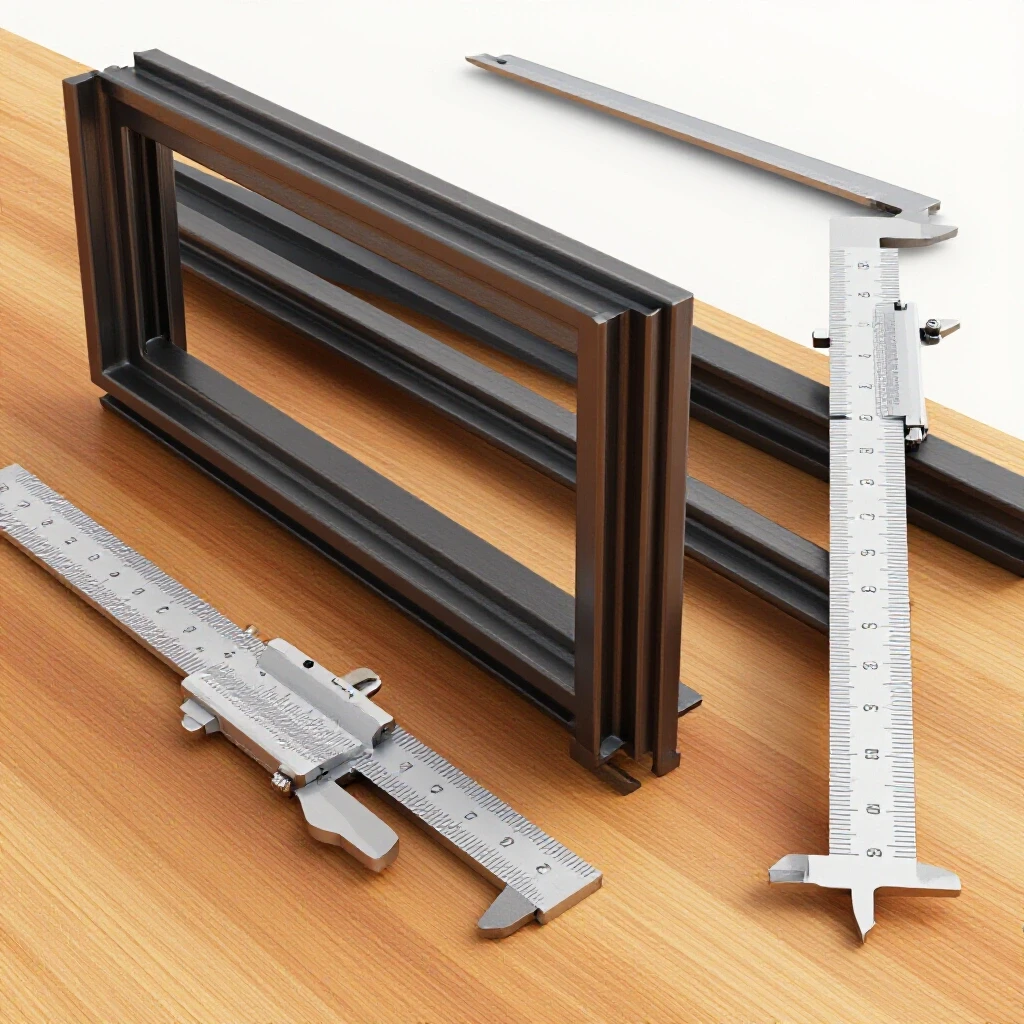
- Feeler Gauges: Use these to check your fit-up gaps. If you can fit a 0.020-inch gauge in a “tight” butt joint, it is not tight enough.
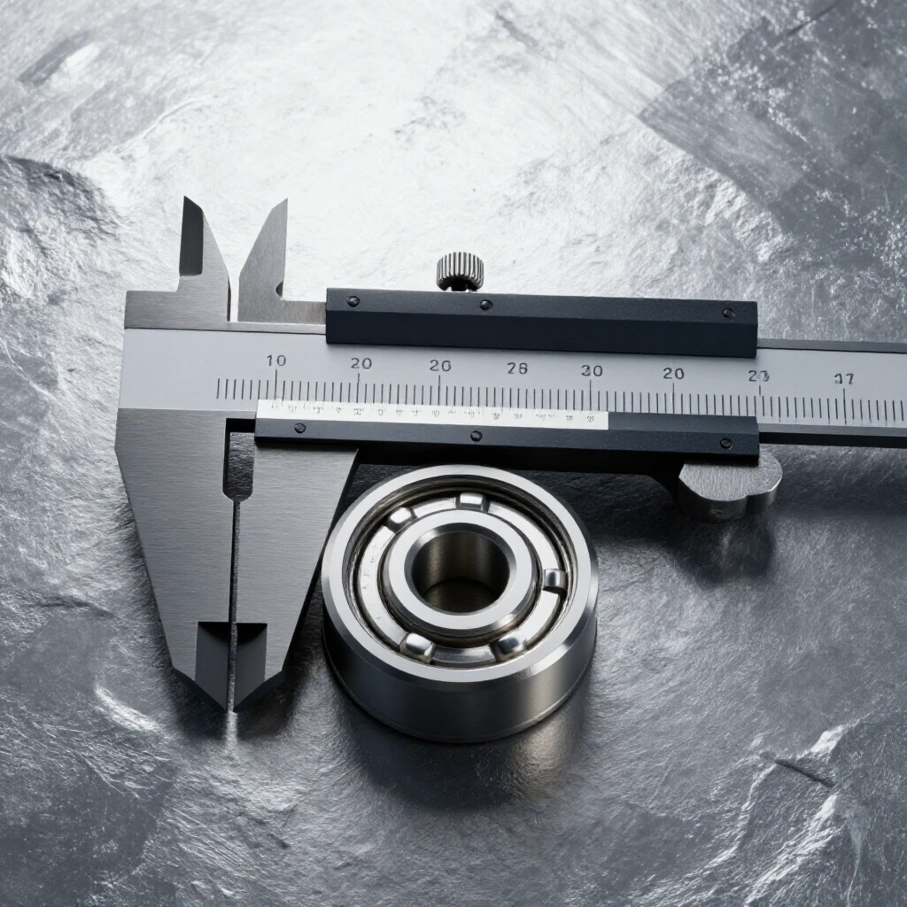
- Digital Dial Indicator: Essential for checking machine alignment and ensuring your workpieces are square. I use this to measure spindle runout if I am welding on a rotary positioner.
- Infrared Heat Tracker: This helps identify “hot spots” in a part that might be causing excessive warping and subsequent gas coverage loss.
- Smartphone Vibration Analyzer: If you are welding on a bench near a running mill or lathe, vibration can actually jitter the gas stream. I use a simple app to check if shop floor harmonics are affecting my arc stability.
Why Machining Chatter and Vibrations Affect Weld Quality
Vibrations or “chatter” are resonant frequencies that can travel through a welding bench or workpiece. These micro-vibrations can destabilize the arc and disrupt the laminar flow of a gas lens, leading to inconsistent bead appearance and internal defects.
This is a problem many fabricators overlook. I once worked in a shop where the TIG station was right next to a large industrial punch press. Every time that press hit, the welder’s arc would flicker. We thought it was an electrical ground issue. After a week of testing cables, I realized the vibration from the press was physically shaking the gas lens’s laminar stream.
It was like trying to pour water into a glass while someone was shaking your arm. We moved the welding table to a different part of the floor and mounted it on rubber isolation pads. The porosity disappeared immediately. If your shop has heavy machinery, your “gas issue” might actually be a “harmonic issue.”
Isolating Rigid Harmonic Vibrations
To test for this, place a bowl of water on your welding bench. If you see ripples on the surface while your machines are idling, you have enough vibration to affect a sensitive TIG arc. You can solve this by: * Using rubber isolation mounts for your welding table. * Ensuring your torch lead is not draped over a vibrating motor or compressor. * Adding mass to your workpiece (clamping it to a heavy steel plate) to change its resonant frequency.
Step-by-Step Diagnostic Path for Weld Defects
This systematic process of elimination helps a fabricator identify the root cause of a defect by testing one variable at a time, starting from the gas source and ending at the joint design.
When a weld goes south, I follow this exact sequence. Do not skip steps, or you will end up chasing your tail.
- Check the Gas Source: Is the tank empty? Is it the right gas (100% Argon for most TIG)?
- Verify Nozzle Flow: Use the portable flow meter at the torch. If the flow is lower than the regulator setting, check for leaks in the lead using soapy water.
- Inspect the Gas Lens: Take the nozzle off. Are the screens clogged with spatter? Are they crushed? A damaged screen will ruin laminar flow.
- Evaluate the Tungsten: Is it contaminated? Even a tiny bit of silicon or aluminum on the tip will destabilize the arc and the gas flow.
- Measure the Fit-Up: Use your feeler gauges. Are the gaps consistent? If the gap varies from 0.005 to 0.030, your gas coverage will vary too.
- Analyze the Joint Shape: Is it a deep pocket? If so, try reducing flow slightly to stop the “swirl” or increasing stick-out to get deeper into the root.
- Test for Environmental Drafts: Turn off any fans or heaters. Even a person walking by can disrupt a gas lens’s flow.
Case Study: The “Mystery Porosity” in a Stainless Manifold
I once consulted for a shop building custom turbo manifolds. They were using high-quality gas lenses, but the welds inside the collector were consistently porous. They had replaced the torches, the gas lines, and even the argon tank.
When I arrived, I watched the welder. He was doing everything right. Then I looked at the joint design. The collector was a “star” shape where four pipes met. The way the pipes were cut left a large, hollow chamber in the center. As he welded the outside, the argon was filling that center chamber and then “burping” back out through the gaps as it heated up and expanded.
The solution wasn’t better gas flow; it was a better assembly sequence. We had him tack the entire assembly and then purge the inside of the manifold with a secondary gas line. By filling the “dead space” with argon, we eliminated the oxygen that was being pushed out into his weld puddle. We also adjusted his edge bevel from 45 degrees to 30 degrees, which allowed the gas lens to sit closer to the joint.
Actionable Benchmarks for Fabrication Success
These metrics provide a standard for fabricators to aim for, ensuring that their mechanical and gas delivery systems are operating within optimal ranges for high-quality results.
- Gas Flow Rate: 12-20 CFH (Going above 25 CFH often causes turbulence with a gas lens).
- Tungsten Stick-out: 2 to 3 times the diameter of the tungsten (e.g., 1/4″ to 3/8″ for a 1/8″ electrode).
- Fit-up Gap: Maximum of 10% of the material thickness for a “no-gap” weld.
- Travel Speed: 3-5 inches per minute for manual TIG on 1/8″ plate.
- Cooling Time: Allow the gas post-flow to run for at least 1 second for every 10 amps of current to protect the cooling puddle.
Conclusion
Mastering the use of a gas lens is not about buying the most expensive nozzle; it is about understanding how your joint design interacts with the air around it. Troubleshooting is a process of elimination. If you start with a clean, well-aligned joint and a systematic check of your gas delivery, those “unsolvable” porosity issues usually disappear. Remember that a gas lens is a precision tool that relies on physics. If you give the gas a smooth path and a clean surface, it will do the work for you. Keep your edges sharp, your gaps tight, and your diagnostic tools ready.
FAQ
Why does my weld have porosity even though I’m using a gas lens? Porosity with a gas lens is usually caused by turbulence or atmospheric draw. If your flow rate is too high (over 25 CFH), the gas can become turbulent. If your joint has a large gap, it can suck in air from the back. Check for leaks in your torch and ensure your metal is chemically clean.
How much tungsten stick-out can I really get with a standard gas lens? Generally, you can stick the tungsten out 2 to 3 times the diameter of the electrode. In some “dead air” environments, you can go up to 1 inch, but you risk losing the gas envelope if there is any breeze at all.
Does the size of the gas lens nozzle matter? Yes. A larger nozzle (like a #8 or #12) provides a wider area of coverage, which is great for reactive metals like titanium or stainless. However, a larger nozzle requires more flow to maintain the same pressure and can be harder to fit into tight corners.
Can I use a gas lens for welding outside? It is difficult. Even with a gas lens, a breeze of more than 5 mph will blow away your shielding gas. If you must weld outside, use welding screens or a tent to block the wind.
How do I know if my gas lens is damaged? Hold the torch up to a light and look through the nozzle. The mesh screens should be flat and uniform. If they are puckered, torn, or covered in brown/black soot, the laminar flow is compromised and the lens should be replaced.
What is the best way to clean a joint for TIG welding? Mechanical cleaning with a clean stainless steel wire brush followed by a wipe-down with 100% acetone is the gold standard. Avoid “brake cleaner,” as it can produce toxic phosgene gas when heated.
Why is my tungsten turning black after the weld? This is a sign of poor post-flow coverage. Your shielding gas should continue to flow until the tungsten has cooled below its oxidation temperature. Increase your post-flow timer on your machine.
Can a bad ground cause porosity? Indirectly, yes. A poor ground causes arc wander. When the arc wanders, you tend to tilt the torch to compensate, which ruins your gas coverage angle and pulls in air.
Should I use a gas lens for carbon steel? While not strictly necessary, a gas lens helps on carbon steel by providing a cleaner puddle and allowing you to see the weld better due to the increased stick-out. It is very helpful for thin-gauge tubing.
What is the “venturi effect” in welding? The venturi effect occurs when high-velocity gas passes over an opening, creating a low-pressure zone that sucks in surrounding air. This happens in welding when your gas flow is too high or your torch angle is too steep near the edge of a joint.
(This article was written by one of our staff writers, Paul Whitaker. Visit our Meet the Team page to learn more about the author and their expertise.)