How to Build a Cheap Welding Fume Exhaust Fan System (Plan)
I have spent eighteen years inside the belly of industrial fabrication mills and custom job shops. In that time, I have learned that the most frustrating problems are rarely the ones that break a machine in half. The real headaches are the “gremlins”—the intermittent weld porosity that appears only on Tuesday mornings, the tool chatter that ruins a finish when the shop gets too warm, or the mysterious vibration that starts the moment you flip on a new piece of equipment.
When you are trying to resolve mechanical or metallurgical issues, you cannot rely on guesswork. You need a system. I remember a specific project back in 2012 where a shop was losing three out of every ten welds to internal voids. They had replaced the gas regulators, the liners, and the wire. It turned out to be a poorly placed floor fan that was pulling the shielding gas away just enough to cause trouble. This taught me that every new addition to a shop, including a simple smoke removal setup, must be integrated with a diagnostic mindset.
Establishing a Systematic Diagnostic Framework for Shop Air Management
A diagnostic framework is a structured method used to isolate variables and identify the root cause of a performance failure. It involves documenting the current state of a machine or process, changing one variable at a time, and measuring the resulting output to confirm if the fix is permanent.
Before you start bolting fans to your ceiling or benches, you have to understand how moving air interacts with your existing equipment. In my experience, most fabricators jump straight to the “how” without considering the “why.” If you install a high-volume air mover to clear out smoke, you might inadvertently introduce a draft that ruins your TIG welds or shakes your precision lathe.
To avoid this, I use a three-step isolation process: 1. Baseline Observation: Record how your machines perform without the new system running. Use a dial indicator to check for spindle runout or a scrap piece of 1/8-inch steel to run a test bead. 2. Variable Introduction: Turn on the new equipment and repeat the exact same tests. 3. Delta Analysis: Look for the difference (the “delta”) between the two results. If your weld porosity spikes or your surface finish degrades, you have isolated the new system as the source of the interference.
| Diagnostic Step | Tool Required | Metric to Track |
|---|---|---|
| Mechanical Alignment | Dial Indicator | Backlash/Runout (0.001″) |
| Vibration Analysis | Smartphone Accelerometer App | Frequency (Hz) and Amplitude |
| Weld Integrity | Visual/Bend Test | Porosity count per inch |
| Electrical Stability | Multimeter | Voltage drop (Max 3%) |
Identifying the Root Cause of Weld Porosity in Ventilated Spaces
Weld porosity is a defect characterized by small pits or holes in the weld bead, usually caused by atmospheric contamination of the weld pool. In a shop with active air evacuation, this is often the result of air currents moving faster than the shielding gas can protect the arc.
When you are troubleshooting weld porosity, you have to look at the flow rate of your shielding gas versus the velocity of the air around your bench. Most MIG or TIG setups run between 15 and 30 Cubic Feet per Hour (CFH). If your new budget ventilation setup is pulling 400 Cubic Feet per Minute (CFM) directly across the arc, the gas won’t stand a chance.
I once worked with a fabricator who was convinced his welder had a faulty solenoid. We did a systematic check: – Checked the tank pressure (it was 1,500 PSI). – Inspected the O-rings in the torch (they were seated). – Measured the air speed at the bench. The air speed was 5 miles per hour because of an unshielded exhaust fan. We resolved it by building a simple “hood” that focused the suction six inches above the weld while leaving the sides protected. This is why a metalworking diagnostic guide always starts with the environment, not just the machine settings.
Selecting Components for a Budget-Friendly Smoke Extraction Setup
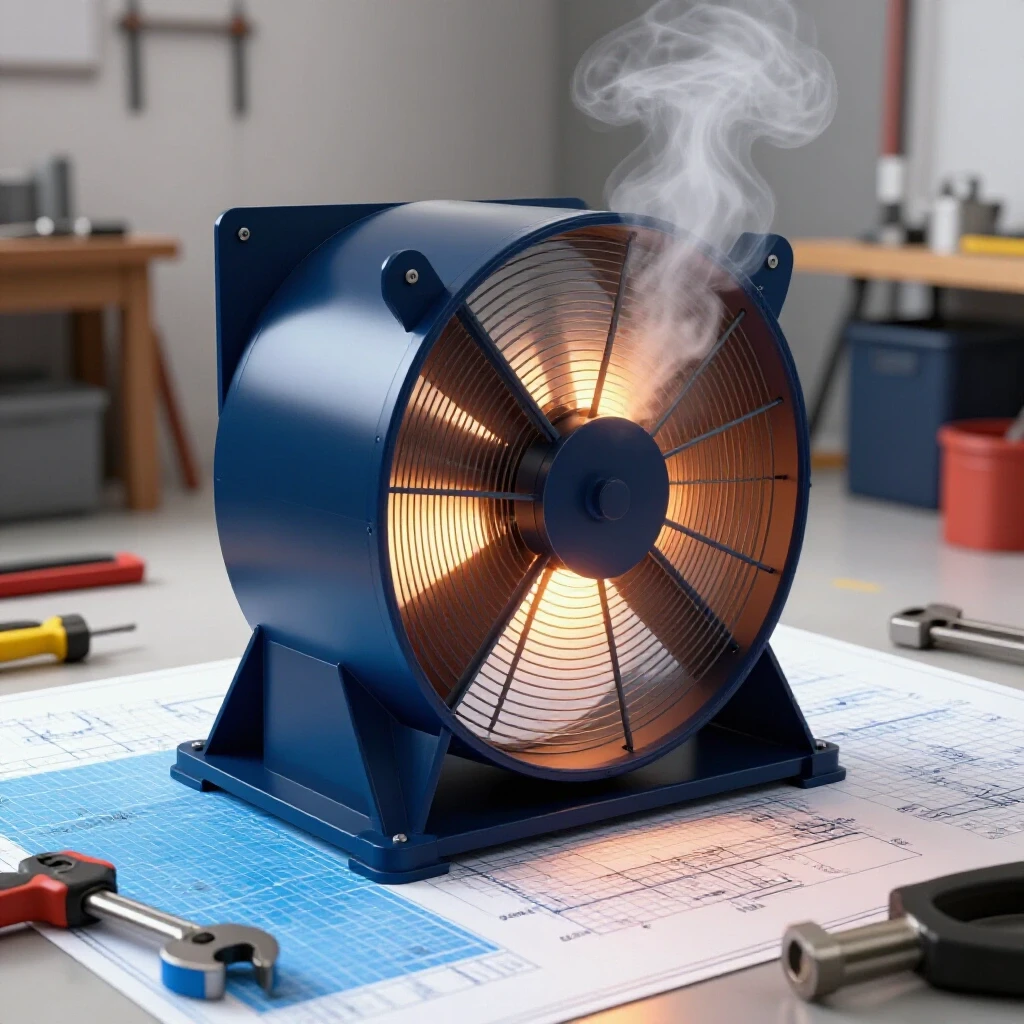
Selecting components for a shop-made air mover involves balancing air volume (CFM) against static pressure and noise. For a low-cost setup, this typically means using an inline duct fan, flexible hosing, and a custom-built collection nozzle that can be positioned near the work area.
You don’t need industrial-grade blowers for a small shop, but you do need a fan that can handle the resistance of a duct. A standard box fan has almost zero static pressure capability; the moment you put a hose on it, the airflow drops to nothing. Instead, I recommend looking for an 8-inch or 10-inch inline “mixed flow” fan. These are common in the hydroponics industry and are surprisingly affordable.
- Fan Choice: Look for a unit rated for at least 400–600 CFM.
- Ducting: Use 8-inch semi-rigid aluminum ducting. It holds its shape better than the thin foil stuff, which reduces “flutter” and noise.
- Mounting: Use rubber isolation grommets where the fan meets the bracket. This prevents the motor’s 60Hz hum from turning your wall into a sounding board.
Addressing Tool Chatter and Vibration from Fan Mounting
Tool chatter is a resonant vibration that occurs when the cutting tool and the workpiece bounce against each other at high frequencies, leaving a wavy finish. In a shop environment, a poorly mounted exhaust fan can transmit vibrations through the floor or bench, triggering these harmonics in a lathe or mill.
If you notice a sudden decline in surface finish quality after installing your air evacuation system, you are likely dealing with mechanical resonance. I have seen cases where a fan spinning at 3,450 RPM (roughly 57 Hz) matched the natural frequency of a bench-top lathe. The result was a “ghost” vibration that made it impossible to hold a tolerance of 0.002 inches.
To diagnose this, I use a simple “kill test.” While the machine is cutting and chattering, have someone else flip the switch on the fan. If the chatter stops instantly, you know the fan is the source. The fix isn’t usually a better fan; it’s better isolation. Use heavy-duty rubber pads or even a dedicated stand that doesn’t touch your primary work surface.
Electrical Troubleshooting for Single-Phase Workshop Fans
Electrical troubleshooting in a shop involves measuring voltage, current, and resistance to ensure that motors are running efficiently and not interfering with other sensitive electronics. For simple plug-in fans, this means checking for voltage drops that could indicate an overloaded circuit.
Most budget fans use a shaded-pole or permanent split capacitor (PSC) motor. These are simple but can be sensitive to voltage drops. If your shop is wired with long runs of 14-gauge wire, and you turn on a 1.5-amp fan while your 15-amp welder is running, you might see a voltage dip. This can cause your welder’s wire feed motor to stutter or the fan to run hot.
- Check Static Voltage: Measure the outlet voltage (should be 115V–125V).
- Check Loaded Voltage: Measure the voltage with the fan and your welder running. If it drops below 108V, you have a circuit capacity issue.
- Ohm’s Law Check: If the fan motor smells hot, check the resistance of the windings. A reading of “OL” (open loop) means a wire has melted, while a very low reading (under 5 Ohms) might suggest a short.
Assembly Sequence for a Mobile Air Evacuation Unit
The assembly sequence is the logical order of operations for building a mechanical system to ensure all parts fit correctly and function as intended. For an exhaust system, this starts with the nozzle, moves through the ducting, and ends at the discharge point.
I prefer a mobile design because fabrication work often moves from the bench to the floor. Building a wooden or metal cart for your fan allows you to position the suction exactly where the smoke is being generated. This minimizes the amount of air you need to move, which in turn reduces the risk of creating drafts that cause weld defects.
- Step 1: The Intake Hood. Cut a 12-inch plastic bucket or a large funnel to act as the “pickup.” Secure it to a magnetic base or an adjustable arm.
- Step 2: Duct Connection. Attach your 8-inch flexible duct to the hood using a heavy-duty worm-gear clamp. Avoid duct tape; the heat from welding will dry out the adhesive in weeks.
- Step 3: Fan Integration. Mount the fan in the middle of the duct run. Having a few feet of duct on both sides of the fan helps “laminarize” the flow, making it quieter and more efficient.
- Step 4: Discharge. Route the exit duct to a window or a dedicated wall port. Ensure the exit is pointed away from your fresh air intake.
Metal Fabrication Fixes: Balancing Airflow and Gas Coverage
In the world of metal fabrication fixes, the most common error is “over-ventilation.” You want to remove the smoke, not the shielding gas. This requires a fine-tuned approach to how you position your intake.
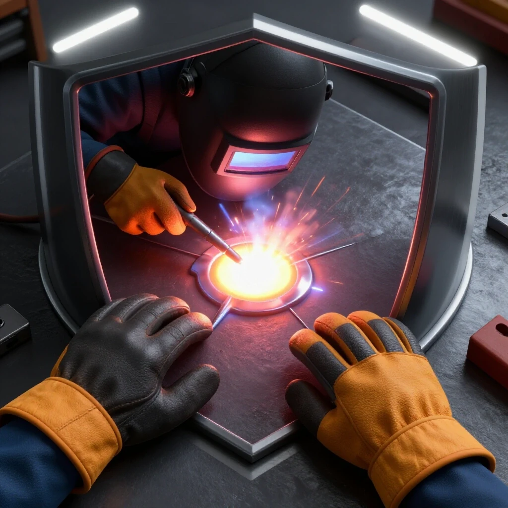
If you are TIG welding stainless steel, you need a very stable gas envelope. Any turbulence will cause the weld to “color” or oxidize. When using your new exhaust setup, keep the intake hood at least 8 to 12 inches away from the arc. At this distance, the fan will still capture the rising plume of smoke (which is hot and wants to go up anyway) without sucking the Argon away from the torch nozzle.
| Airflow Velocity (FPM) | Effect on Shielding Gas | Recommended Action |
|---|---|---|
| 0 – 50 FPM | Minimal | Ideal for TIG/MIG |
| 50 – 100 FPM | Moderate Draft | Increase gas flow by 5 CFH |
| 100+ FPM | Severe Turbulence | Move exhaust hood further away |
Case Study: Isolating the “Ghost” Chatter in a Custom Parts Shop
I once consulted for a small shop that had just installed a series of low-cost ceiling fans to move air. Suddenly, their CNC mill started producing parts with a 0.005-inch ripple. They spent two days checking the spindle backlash and the gib adjustments. They even replaced the X-axis lead screw.
When I arrived, I noticed that the ceiling fans were mounted to the same structural I-beams that supported the shop floor. The fans were slightly out of balance. By using a smartphone vibration spectrum analyzer, we found a spike at 28 Hz that perfectly matched the fan’s rotational speed. The solution wasn’t a $2,000 machine repair; it was $50 worth of rubber vibration isolators for the fan mounts. This is why mechanical troubleshooting steps must always look at the shop as a whole system, not just the machine in isolation.
Practical Tracking Framework for Shop Maintenance
To stay ahead of these issues, I keep a simple logbook. Whenever I add a new tool or change a process, I record the data. This helps me find “intermittent electrical gremlins” or wear patterns before they cause a failure.
- Vibration Baseline: Log the “idle” vibration of your main benches once a month.
- Voltage Log: Check the voltage at your welder’s plug under load every quarter.
- Filter/Duct Inspection: Check for dust buildup in your exhaust system every 50 hours of welding. Dust increases “static pressure,” which makes the fan work harder and move less air.
- Consumable Tracking: Keep a tally of how often you change contact tips. If a new fan setup is causing more spatter, your tip life will drop—a clear sign of a problem.
Conclusion and Next Steps for Your Shop Setup
Mastering shop diagnostics is about moving from “I think” to “I know.” Building a low-cost air evacuation system is a great project, but its success depends on how well you integrate it into your workflow without disrupting your precision.
Your next steps should be: – Identify a 115V circuit that has at least 5 Amps of “headroom” for a fan motor. – Purchase an inline fan and semi-rigid ducting rather than using a standard household fan. – Build a test piece to measure your weld quality before and after the fan is installed.
By following a systematic approach, you can keep your shop air clean while maintaining the high standards of your metalwork. Don’t let a simple fan become the source of your next great troubleshooting mystery.
Frequently Asked Questions
Can I use a standard bathroom exhaust fan for my welding bench? No. Bathroom fans are designed for very low volumes of air and have almost no ability to push air through a long duct. They also use plastic housings that can melt if a hot spark enters the intake. An inline mixed-flow fan is a much better choice for durability and CFM.
Why does my MIG welder start popping when I turn the exhaust on? This is a classic sign of shielding gas disruption. The fan is likely creating a draft that is blowing the gas away before it can protect the weld pool. Try moving the intake hood further away or using a “gas lens” if you are TIG welding to create a more stable flow.
How do I know if my fan is causing vibration in my lathe? The easiest way is to use a dial indicator. Place the indicator on the lathe’s tool post, touching a piece of round stock in the chuck. Turn the fan on and off. If the needle moves even 0.0005 inches when the fan starts, you have a vibration transfer issue that needs to be addressed with isolation pads.
What is the best material for a DIY fume hood? Plywood is cheap and easy to work with, but it is a fire hazard in a welding environment. I recommend using 22-gauge galvanized sheet metal or even a repurposed metal kitchen hood. If you use plastic, keep it at least 18 inches away from the actual arc to prevent melting.
Does duct length affect how well the fan works? Yes. Every foot of duct and every 90-degree bend adds “static pressure” or resistance. A fan that moves 400 CFM in open air might only move 250 CFM through 10 feet of corrugated hose. Keep your runs as short and straight as possible.
How can I tell if a fan motor is starting to fail? Listen for a high-pitched whine (bearing failure) or a deep growl (winding issues). You can also use an infrared thermometer to check the motor housing; if it exceeds 150°F (65°C), it is likely overloaded or the capacitor is failing.
Is it safe to vent welding fumes directly outside without a filter? In a small-scale, non-industrial DIY setup, venting small amounts of smoke outside is common. However, you should ensure the exhaust isn’t pointing at your neighbor’s window or your own air conditioner intake. For heavy production, filtration becomes necessary, but for a budget setup, simple evacuation is the first step.
Can I use a variable speed controller on any fan? Only if the motor is “speed controllable.” Most PSC motors can handle a basic triac-based speed controller, but some cheaper motors will hum or overheat. Check the motor label before adding a dimmer-style switch.
(This article was written by one of our staff writers, Paul Whitaker. Visit our Meet the Team page to learn more about the author and their expertise.)