How to Build a Mobile Hardware Organizer Bin Shop Cart (Plan)
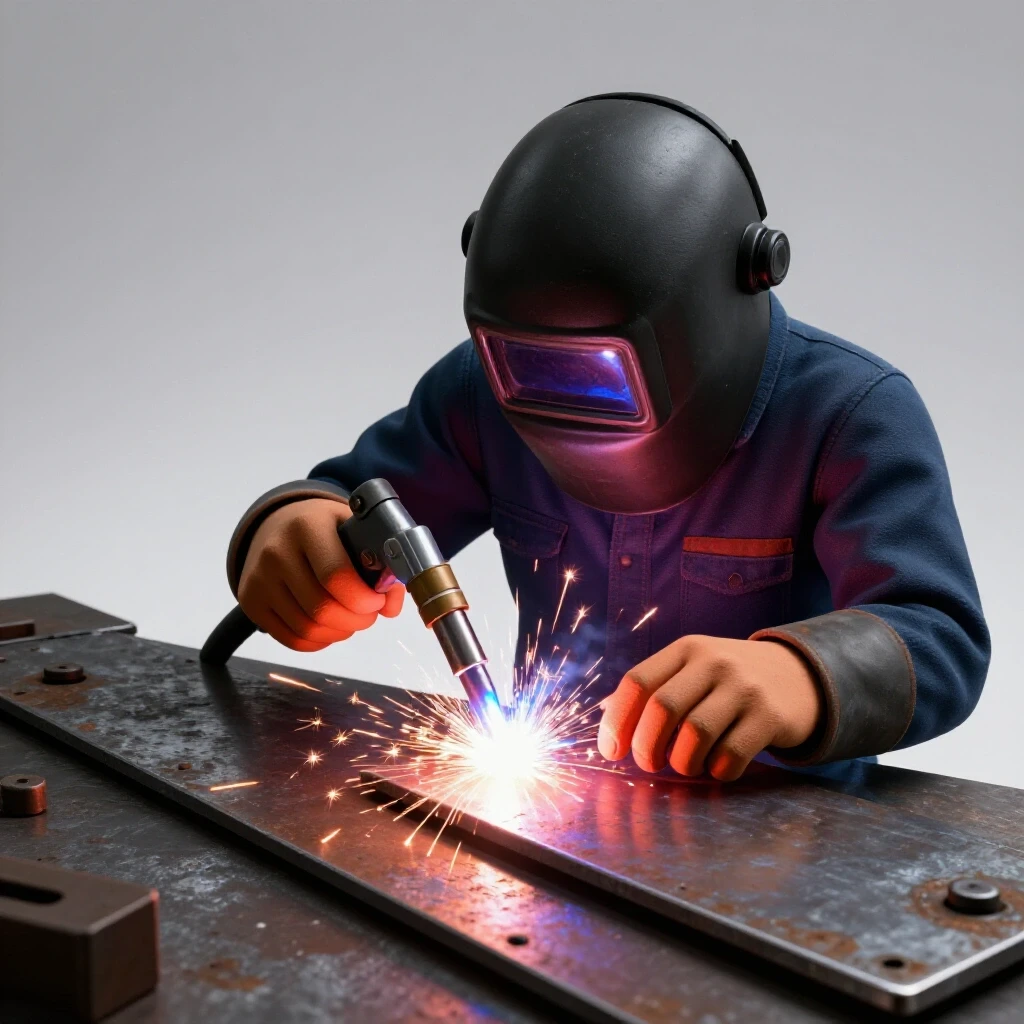
I still remember the first time I tried to build a heavy-duty rolling rack. I had spent hours measuring and cutting every piece of steel to what I thought was the exact length. I clamped the base together, felt confident, and started running long, beautiful beads down every seam. By the time the metal cooled, the entire frame had twisted nearly two inches off the table. It looked more like a Pringles chip than a shop fixture. That project taught me a hard lesson: metal is alive. It moves, it pulls, and if you don’t have a plan to manage the heat, it will fight you every step of the way.
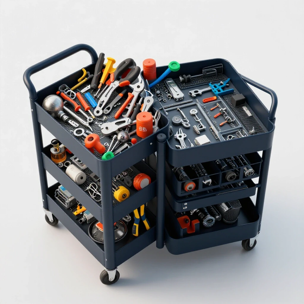
Building a mobile hardware organizer requires more than just sticking pieces of metal together. Because this project involves multiple parallel rails to hold plastic bins, even a small amount of warping can make the bins jam or fall out. In my 13 years as a technician, I’ve learned that success happens in the layout and the sequencing. We are going to walk through the process of constructing a rigid, square steel frame that stays true from the first tack to the final caster installation.
Planning Your Fabrication Layout and Material Selection
Planning involves creating a detailed cut list and selecting steel profiles that balance weight and rigidity. For a bin cart, this means accounting for the outer dimensions of the plastic bins and the thickness of the steel to ensure a snug but functional fit for every shelf. You must visualize how the joints overlap to calculate your final lengths accurately.
Before you strike an arc, you need a blueprint that accounts for the “stack-up” of your materials. For a standard hardware station, I prefer using 1-inch square tubing for the main uprights and 1-inch angle iron for the bin runners. Square tubing provides excellent torsional rigidity, which prevents the cart from swaying when fully loaded with bolts and heavy fasteners.
When designing your layout, always measure your bins first. If a bin is 5 inches wide, your clear opening between the vertical tubes should be 5-1/8 inches. That extra 1/8 inch is your “fudge factor.” It allows for slight variations in the plastic molding and prevents the bins from binding if the frame pulls inward by a fraction of a degree during welding.
- Material Choice: 1″ x 1″ x 11-gauge (1/8″) square tubing for the frame.
- Runner Choice: 1″ x 1″ x 1/8″ angle iron.
- Tolerance Goal: +/- 1/16″ across the total height of the unit.
- Load Consideration: Ensure the base is wider than the top to maintain a low center of gravity.
Calculating Kerf and Achieving Accurate Square Cuts
Kerf is the width of material removed by a cutting tool, such as a chop saw blade or an abrasive disc. Failing to account for this 1/16-inch to 1/8-inch gap results in a frame that is too short, leading to gaps that are difficult to fill with weld. Proper kerf management ensures that your final assembly matches your intended dimensions.
I have seen many builders mark a line at 24 inches and cut right down the middle of that line. If your blade is 1/8-inch thick, your piece is now 23-15/16 inches long. That 1/16-inch error might not seem like much, but when you have four uprights, those errors compound. Suddenly, your cart has a built-in wobble that no amount of grinding can fix. Always “leave the line” on the workpiece side of the cut.
| Tool Type | Average Kerf Width | Best Use Case |
|---|---|---|
| Abrasive Chop Saw | 1/8″ (0.125 in) | Rough breakdown of long sticks |
| Cold Saw | 3/32″ (0.093 in) | High-precision, cool-to-touch cuts |
| Portable Band Saw | 1/16″ (0.062 in) | Detailed fit-up and notch work |
| Angle Grinder (Thin Disc) | 3/64″ (0.045 in) | Trimming and tight-access cuts |
To keep your custom fabrication projects on track, I recommend using a “stop block” on your saw table. Once you set the length for your vertical uprights, you can cut all four pieces without re-measuring. This ensures that even if your measurement is slightly off, all four legs are exactly the same length, which is the key to a level cart.
Building Workshop Jigs and Fixtures for Frame Alignment
Jigs are temporary structures or clamps used to hold workpieces in a fixed position during assembly. Using a flat reference surface and specialized corner clamps ensures that the vertical uprights of your bin station remain perpendicular to the base during the initial tacking phase. A good jig acts as a second set of hands that never gets tired.
You don’t need a professional 3D welding table to get square results. I often build “disposable jigs” right on my plywood workbench by screwing down scrap blocks of wood or metal to create a 90-degree pocket. For this hardware cart, you want to build the two side “ladders” first. By laying the uprights down on a flat surface and clamping the horizontal bin runners between them, you can ensure both sides of the cart are identical mirrors of each other.
- Clear your work surface and check it for flatness with a straightedge.
- Lay out your two vertical tubes and use a framing square to align them.
- Clamp “cleats” (scrap metal or wood blocks) to the table to lock the tubes in place.
- Check the diagonal measurements; if the distance from the top-left corner to the bottom-right corner matches the top-right to bottom-left, the frame is square.
- Use copper heat sinks or aluminum blocks behind thin-wall tubing to help dissipate heat during the tacking process.
Structural Tacking Strategies to Prevent Initial Movement
Tacking involves placing small, temporary weld beads at strategic points to hold the assembly together before final welding. These tacks must be strong enough to resist the initial pull of cooling metal but small enough to be easily ground away if the alignment needs adjustment. Proper tacking is the primary defense against metal warping.
When I start a custom fabrication project, I never weld a joint solid right away. I place a small tack—about the size of a pencil eraser—on the corners. For square tubing, I place tacks on opposite corners (e.g., top-right and bottom-left). As the weld cools, it shrinks. If you only tack one side, the cooling metal will act like a hinge and pull the upright toward the weld. By tacking opposite sides, the forces pull against each other, keeping the part centered.
- Tack Size: Aim for a 1/8″ diameter bead with good penetration.
- Spacing: For a 1-inch tube, two tacks per joint are usually sufficient for the layout phase.
- Verification: After tacking the entire side frame, re-measure your diagonals. If the heat pulled it 1/16″ out of square, you can easily break a tack with a cold chisel and reset it.
- Sequence: Tack the four corners of the main rectangle first, then tack the internal bin runners.
Why Weld Shrinkage Warps Square Structures—And the Precise Order to Lay Your Beads
Weld shrinkage occurs as molten metal cools and contracts, exerting thousands of pounds of force on the joint. By sequencing welds—moving from one side of the frame to the opposite—you can use these forces to counteract each other, keeping the bin rails straight. Understanding this “angular pull” is what separates a technician from a hobbyist.
When you lay a bead of weld, you are essentially casting a tiny piece of molten steel. As it transitions from liquid to solid, it loses volume. This contraction pulls the surrounding metal toward the center of the weld. If you weld all the joints on the front of your cart first, the whole frame will bow forward. To combat this, I use a “staggered” weld sequencing layout.
| Weld Order | Location | Purpose |
|---|---|---|
| 1 | Joint A – Front Face | Establishes the primary connection |
| 2 | Joint B – Opposite Back Face | Counteracts the pull of Weld 1 |
| 3 | Joint A – Inside Face | Closes the internal corner |
| 4 | Joint B – Opposite Inside Face | Balances the internal tension |
By jumping from corner to corner and side to side, you allow the heat to dissipate evenly. I often tell people to “chase the heat.” If one corner feels hot to the touch, move to the furthest possible corner for your next weld. This prevents any single area of the steel from reaching a temperature where it becomes plastic and loses its structural memory.
Controlling Heat Warp During Rail and Caster Installation
Heat warp is the permanent deformation of metal caused by uneven heating and cooling. When welding long angle iron rails for bin supports, short intermittent beads are preferred over long continuous passes to minimize the “banana” effect on the steel. This is especially critical when the rails must remain perfectly parallel for the bins to slide.
The bin runners are the most sensitive part of this build. If you weld a 12-inch piece of angle iron with a continuous bead, it will almost certainly bow in the middle. Instead, use “stitch welding.” Place a 1/2-inch weld at the front, one in the middle, and one at the back. For the loads seen in a hardware cart, this is more than enough strength, and it drastically reduces the total heat input into the vertical uprights.
If you are welding a flat plate to the bottom of the tube for the caster to bolt into, the plate will want to curl upward.- Clamp heavily: Use C-clamps to hold the caster plate flat against a thick metal table or a heavy piece of channel iron during welding.
- Cool slowly: Do not quench the welds with water. Rapid cooling can make the steel brittle and increase the internal stresses that cause warping.
- Back-stepping: Start your weld 1 inch away from the edge and weld toward the edge. This technique, called back-stepping, helps manage the way the metal expands in front of the arc.
Correcting Distortion and Final Straightening Techniques
Final straightening involves using controlled heat or mechanical force to bring a warped frame back into tolerance. If a shelf rail bows after welding, applying heat to the opposite side or using a heavy-duty clamp can often pull the steel back to a level state. Even with perfect sequencing, some movement is inevitable.
If you finish your cart and find that one corner is “light” (it doesn’t touch the floor), don’t panic. You can often fix this using a technique called “flame straightening” or simply by using mechanical leverage. If the frame is twisted, I often clamp one end to a heavy table and use a long pry bar or a floor jack to gently “tweak” the frame back into alignment.
Another trick is the “shrinkage” method. If a tube is bowed toward you, you can run a quick, hot bead on the opposite side (the “high” side of the curve). As that new weld cools, it will pull the metal toward it, effectively pulling the bow out of the tube. This requires a bit of practice, but it is a standard tool in the custom fabrication projects toolkit.
- Identify the direction of the warp using a long straightedge.
- Mark the “peak” of the curve.
- Apply localized heat or a small weld bead to the side you want the metal to move toward.
- Allow it to air cool completely before checking the progress.
- Repeat in small increments; it is easier to add more heat than to fix an over-correction.
Actionable Framework for a Successful Build
To ensure your mobile hardware organizer comes out straight and functional, follow this checklist during your shop sessions. Tracking your progress helps prevent the “rushed” mistakes that lead to significant alignment issues.
- Cut List Verification: Measure every piece twice. Group identical lengths together and verify they match to within 1/32″.
- Surface Prep: Grind the mill scale off the steel at every weld location. Clean metal requires less heat to penetrate, which reduces warping.
- The Square Check: Before any welding, check the “3-4-5” triangle on your base frame to ensure a perfect 90-degree corner.
- Tack Sequencing: Follow a “star pattern” similar to tightening lug nuts on a car wheel.
- Weld Monitoring: Touch the metal near your previous weld. If you can’t keep your hand near it, it’s too hot. Move to a different section of the cart.
- Caster Alignment: Ensure your caster plates are parallel to the ground. A tilted caster will make the cart difficult to steer and cause it to “track” to one side.
By focusing on these structural considerations, you turn a simple weekend project into a piece of shop furniture that will last for decades. The goal isn’t just to have a place for your nuts and bolts; it’s to master the physics of metalwork so that your next project—whether it’s a trailer or a workbench—is even more precise than the last.
Frequently Asked Questions
How do I stop the 1-inch tubing from blowing through when welding?
Blow-through usually happens because of excessive heat or a gap that is too wide. Ensure your pieces are fit tight with no visible light between the joints. Use a “pulsing” technique with your MIG trigger if you are working with thinner 14-gauge or 16-gauge tubing, and keep your wire speed high enough to cool the puddle as you move.
Why does my frame stay square when tacked but warp after final welding?
This is caused by the cumulative force of weld shrinkage. A tack weld is small and has limited pull. A full bead has much more volume and, therefore, more contraction force. To prevent this, never weld one joint completely before moving to the next. Use the staggered sequencing mentioned earlier to balance the forces.
Can I use a regular wood level to check my cart?
A level only works if your floor is perfectly flat. In most garages, the floor slopes for drainage. Instead of a level, use a framing square and “cross-indexing” measurements. Measuring the diagonals (corner to corner) is the most accurate way to check for “rack” in a rectangular frame.
What is the best way to weld the angle iron runners without them bowing?
Use the “stitch weld” method. Instead of a continuous bead along the entire length of the angle iron, place 1/2-inch welds every 4 to 6 inches. This provides plenty of shear strength for holding hardware bins while keeping the heat input low enough to prevent the “banana” effect.
Should I weld the casters directly to the frame?
I don’t recommend it. Welding directly to the caster housing can melt the internal grease or damage the ball bearings. Always weld a mounting plate (at least 3/16″ thick) to the frame first, then bolt the casters to the plate. This also makes it easier to replace a damaged caster later.
How do I handle gaps if my cuts aren’t perfectly square?
If you have a gap, do not try to bridge it with one heavy bead; this creates massive heat and warping. Instead, “butter” the edges by adding a small amount of weld to each side of the gap to narrow it, let it cool, and then join them with a final pass.
What is “angular distortion” and how does it affect my bin rails?
Angular distortion is when the vertical legs of your cart pull inward because of the welds on the inside of the frame. To fight this, you can “pre-set” the legs by leaning them slightly outward (about 1 or 2 degrees) before welding. As the weld shrinks, it will pull the legs into a perfectly vertical position.
Is it better to weld the inside or the outside of the corners first?
I prefer welding the outside corners first. This creates a rigid “spine” for the joint. When you later weld the inside, the outside weld acts as a mechanical stop, preventing the heat from pulling the joint too far inward.
How can I tell if my weld sequencing is working?
Keep a framing square handy. After every two or three welds, check the critical 90-degree joints. If you see the gap starting to open or close, change your welding order immediately to pull the metal back in the opposite direction.
Does the thickness of the steel affect how much it warps?
Yes. Thinner steel (like 16-gauge) heats up much faster and warps more easily than thicker 11-gauge tubing. For a shop cart, 11-gauge (1/8″) is the “sweet spot” because it is thick enough to be forgiving during welding but light enough to remain mobile.
(This article was written by one of our staff writers, Robert Kline. Visit our Meet the Team page to learn more about the author and their expertise.)