How to Build a Solid Steel Bike Repair Stand (DIY Tutorial)
I have spent the last 13 years in fabrication shops and home garages, and I have learned one hard truth: steel is never static. It moves, it pulls, and if you do not respect the heat, it will turn your carefully measured project into a twisted mess. I remember building my first heavy-duty utility trailer; I had every piece cut to the sixteenth of an inch. But because I did not understand weld sequencing, the entire rear gate ended up three-quarters of an inch out of square.
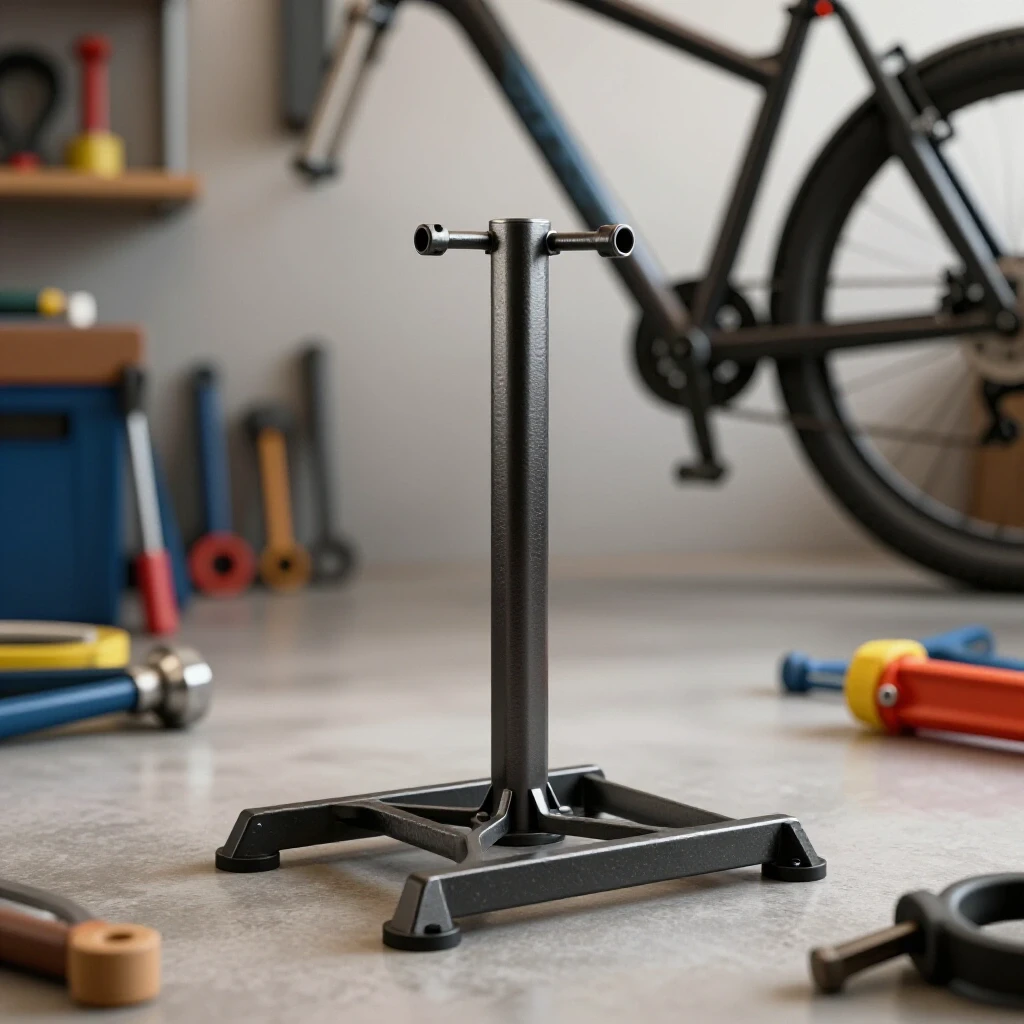
That experience changed how I approach every custom fabrication project. When you are building a heavy-duty maintenance fixture, like a stand designed to hold a bicycle at eye level, precision is everything. If the vertical mast is not plumb or the base is not flat, the whole structure becomes a safety hazard. This guide focuses on the technical side of building a rigid, adjustable workshop tool using mild steel. We will look at how to manage metal warping solutions, ensure accurate square cuts, and use workshop jigs and fixtures to keep your work straight.
Designing the Cutting List and Material Selection
A cutting list is a detailed inventory of every metal component needed for a build, accounting for the specific dimensions of the final product and the waste produced during the cutting process. It serves as the primary roadmap for the project, ensuring you have enough raw stock before the first arc is struck.
In my shop, I prefer using 2-inch square tubing with a 1/8-inch wall thickness for the main uprights. This provides the necessary rigidity without making the unit too heavy to move. For the base legs, I often go with slightly thicker 3/16-inch wall tubing to lower the center of gravity. When you plan your layout, you must account for the thickness of the steel itself. If you want a 30-inch wide base, and you are welding the legs to the side of a center post, the legs themselves need to be shorter to account for that center post width.
Calculating Kerf and Cutting Accuracy
Kerf is the width of the material removed by a cutting tool, such as a saw blade or a grinding disc, during the fabrication process. Failing to account for kerf can result in components that are too short, leading to gaps that are difficult to fill with weld metal.
When I use a standard 14-inch abrasive chop saw, the kerf is usually about 1/8 of an inch. If I need four pieces at exactly 24 inches, and I just mark 24, 48, 72, and 96 on a single stick of steel, the last piece will be nearly half an inch short. Always measure each piece individually after the previous cut is made.
| Tool Type | Average Kerf Width | Accuracy Level |
|---|---|---|
| Abrasive Chop Saw | 0.125″ (1/8″) | Moderate |
| Cold Saw | 0.100″ | High |
| Angle Grinder (Thin Cut-off) | 0.045″ | Low (Manual) |
| Portable Band Saw | 0.035″ | High |
Preparing the Steel for Layout
Surface preparation involves removing mill scale, rust, and oils from the steel to ensure a clean surface for marking and a high-quality weld. Clean steel allows for more accurate layout lines and prevents weld defects like porosity or lack of fusion.
I never start a layout on raw, scaly steel. I use a flap disc to clean the areas where my marks will go. Mill scale is a layer of oxidized iron that forms during the hot-rolling process; it is hard, brittle, and will clog your files and ruin your weld penetration. Once the metal is shiny, I use a high-visibility layout fluid or a fine-point scribe. A soapstone marker is okay for rough work, but for a precision workshop tool, a scribe line is much more accurate.
Creating Workshop Jigs and Fixtures for Alignment
Workshop jigs and fixtures are temporary or permanent structures used to hold workpieces in a fixed position during the assembly and welding process. They are essential for maintaining dimensional tolerances and preventing parts from shifting under the stress of clamping or thermal expansion.
When you are building a vertical structure, gravity is your enemy. I often weld temporary “stoppers” or “cleats” onto my heavy steel welding table. These are just small scraps of angle iron that I tack-down to create a 90-degree corner. By sliding my square tubing into this corner, I know the base is square before I even pick up the torch. This is a foundational step in any custom fabrication project where alignment is critical.
The Importance of a Flat Reference Surface
A reference surface is a known flat plane, such as a cast-iron welding table or a leveled steel plate, used to ensure that all components of a build are on the same level. Without a flat surface, the base of your stand will rock, no matter how square your corners are.
If you are working on a concrete garage floor, do not assume it is flat. I have seen floors with a 1/2-inch slope over just four feet. If you must build on the floor, use shims and a long machinist’s level to create a flat “sub-frame” out of scrap steel. This acts as a temporary table. I once built a set of heavy-duty shelves on an uneven floor; once I moved them to the flat shop floor, they looked like the Leaning Tower of Pisa.
Using Clamps to Fight Thermal Pull
Clamping is the act of physically restraining metal components to prevent them from moving during the welding process. Proper clamping techniques counteract the internal stresses that occur as weld metal cools and shrinks.
I use a “clamp-heavy” approach. For every joint, I want at least two points of contact. When you weld a T-joint, the weld will pull the upright piece toward the side you are welding. By using a heavy C-clamp and a piece of thick plate as a backing, you can resist some of that pull. However, remember that no clamp can stop 100% of the movement; the goal is to manage it.
- Use F-style clamps for quick adjustments.
- Use heavy-duty C-clamps for high-pressure restraint.
- Place clamps as close to the joint as possible without obstructing the weld path.
- Check squareness after applying clamp pressure but before welding.
Mastering Weld Sequencing Layout and Heat Control
Weld sequencing layout refers to the strategic order in which welds are applied to a structure to balance the forces of thermal expansion and contraction. By alternating sides and positions, a fabricator can minimize the overall distortion of the project.
Every time you lay a bead, the liquid metal occupies a larger volume than it does when it cools. As it solidifies, it shrinks. This shrinkage acts like a powerful winch, pulling the metal in the direction of the weld. In my early years as a prototype technician, I learned that if I welded the entire front of a joint and then the back, the piece would always be crooked. You have to “leapfrog” your welds.
The Science of Angular Distortion
Angular distortion is the change in the angle between two components caused by the shrinkage of the weld metal at the joint. This is most common in fillet welds, where the horizontal and vertical plates are pulled toward each other.
For a 1/4-inch fillet weld on 1/8-inch wall tubing, you can expect between 1 and 3 degrees of angular pull if the joint is not restrained. To combat this, I sometimes “pre-set” my parts. If I know the weld will pull the mast 2 degrees to the left, I might clamp it 2 degrees to the right. This is an advanced metal layout tip that requires practice to master.
Implementing a Symmetrical Weld Sequence
A symmetrical weld sequence involves applying small sections of weld in a pattern that mirrors itself across the center of the project. This ensures that the pulling forces on one side are cancelled out by the pulling forces on the opposite side.
When I weld the base of the stand, I follow a specific pattern. I start with a 1-inch bead on the “North” side, then move to the “South” side. Then I move to “East” and “West.” This keeps the heat input balanced.
- Place the first 1/2-inch tack on the corner.
- Place the second tack on the opposite corner.
- Check for squareness using a framing square.
- Weld the first 1-inch segment on the outside of the joint.
- Move to the opposite side of the frame and weld the corresponding segment.
- Allow the metal to cool to the touch before finishing the remaining beads.
Structural Tacking and Dimensional Tolerances
Tacking is the process of making small, temporary welds to hold an assembly together before the final structural welds are applied. These tacks must be strong enough to resist the initial heat of the welding process but small enough to be easily ground away if an error is found.
I see many beginners make tacks that are too small. A tiny “bird dropping” tack will pop the moment the metal starts to expand from the main weld. Your tacks should be about 1/4 inch to 3/8 inch long and have good penetration. I usually place tacks at every corner of a square tube. This creates a “cage” that holds the dimensions tight.
Maintaining Tight Dimensional Tolerances
Dimensional tolerances are the allowable limits of variation in a physical dimension. In high-quality custom fabrication projects, staying within a tolerance of +/- 1/16th of an inch is a standard goal for garage-built fixtures.
To keep my tolerances tight, I use a “measure three times” rule. 1. Measure after the cut. 2. Measure after the layout. 3. Measure after the tacks are set.
If I find that my mast is 1/8 of an inch off-center after tacking, I don’t try to “weld it straight.” I cut the tacks with a thin zip-disc, re-align, and re-tack. It is much easier to fix a tack than a full-depth structural weld.
Tack Spacing and Sizing Benchmarks
The spacing and size of tacks depend on the thickness of the material and the length of the joint. Proper tacking prevents the “zipper effect,” where a long joint slowly opens or closes as you weld down its length.
| Material Thickness | Tack Length | Recommended Spacing |
|---|---|---|
| 1/8″ (11 gauge) | 1/4″ | Every 3-4 inches |
| 3/16″ (7 gauge) | 3/8″ | Every 5-6 inches |
| 1/4″ Plate | 1/2″ | Every 6 inches |
Fabricating the Adjustable Clamping Mechanism
The clamping mechanism is the functional heart of the maintenance stand, requiring precise alignment to ensure it can securely grip a load without slipping. This part of the build often involves moving parts, which means tolerances must be even tighter to prevent binding.
For the clamp, I often use a “tube-in-tube” design. This involves a smaller square tube sliding inside a larger one. This is where metal warping solutions become vital. If you weld a nut onto the outer tube for a locking bolt, the heat can distort the tube enough that the inner one will no longer slide. To prevent this, I slide the inner tube into place before welding the nut, using it as a heat sink to keep the outer tube’s shape.
Aligning the Rotation Axis
The rotation axis is the point around which the clamp head turns, allowing the object being held to be positioned at various angles. If this axis is not perfectly perpendicular to the vertical mast, the load will “swing” unevenly.
I use a simple jig for this: a long piece of threaded rod passed through both the mast and the clamp head. This ensures the holes are perfectly aligned. I then tack the pivot hardware in place while the rod is still inserted. This prevents the holes from “walking” out of alignment during the welding process.
- Drill holes using a drill press for 90-degree accuracy.
- Use a deburring tool to ensure smooth rotation.
- Apply a thin layer of lithium grease to the sliding surfaces after painting.
Post-Weld Alignment and Correcting Distortion
Post-weld alignment is the process of inspecting the finished assembly for any warping or movement that occurred during welding and correcting those errors. Even with perfect sequencing, some movement is almost inevitable in steel fabrication.
If you find a part has pulled out of square, you have two main options: mechanical force or heat straightening. Mechanical force involves using a large pipe wrench or a hydraulic jack to “tweak” the metal back. Heat straightening is more surgical. By heating a small triangular area on the side opposite the warp, you can cause the metal to shrink and pull the piece back into alignment.
Using Heat Sinks to Minimize Damage
A heat sink is a mass of conductive material, usually copper or a thick block of aluminum, placed near a weld to soak up excess thermal energy. This reduces the size of the heat-affected zone (HAZ) and limits the amount of warping.
When I weld thin-walled tubing, I often clamp a thick piece of scrap steel right next to the joint. This scrap acts as a sponge for the heat. It won’t stop the weld from shrinking, but it will keep the rest of the tube from getting hot enough to lose its structural integrity or bow.
Final Inspection Checklist
Before you call the project finished and reach for the paint, you must perform a final quality check. This ensures the stand is safe and functional.
- Check for Plumb: Is the main mast vertical when the base is on a level surface?
- Check for Square: Are the base legs at 90 degrees to the center post?
- Inspect Weld Quality: Are there any cracks, undercut, or visible porosity?
- Test Movement: Does the clamp slide and rotate smoothly through its full range?
- Load Test: Apply a weight greater than the intended load to check for structural flexing.
Conclusion and Next Steps
Building a high-quality workshop fixture is a masterclass in managing the physical properties of steel. By focusing on accurate square cuts, implementing a disciplined weld sequencing layout, and using workshop jigs and fixtures, you can overcome the common frustrations of metal warping. Remember that fabrication is as much about planning and layout as it is about the actual welding.
Your next step is to clear your workbench and start your cutting list. Begin by prepping your steel and cleaning off that mill scale. If you take the time to set up your jigs and sequence your welds properly, you will end up with a tool that is not only functional but professionally straight.
FAQ: Common Challenges in Steel Fabrication Projects
How do I stop my square tubing from twisting when I weld the base?
Twisting is usually caused by welding all the way around one joint before moving to the next. To prevent this, use a “cross-pattern” tacking method. Tack all four corners of every joint in the base first. Then, weld the “inside” corners of the entire base, followed by the “outside” corners. This balances the tension across the entire structure.
What is the best way to get perfectly square cuts without an expensive cold saw?
If you are using an angle grinder or a chop saw, use a “wrap-around” template. Take a straight piece of paper, wrap it around the tube, and align the edges. Trace the line with a scribe. This gives you a perfect 360-degree line to follow. Cut slightly outside the line and use a flap disc to “sneak up” on the final dimension.
Why do my welds crack when I try to straighten a warped part?
Cracking occurs because the metal has become brittle or because you are applying force to a cold weld that is under high internal stress. If you need to mechanically straighten a joint, apply a small amount of heat to the area first to make the steel more ductile. Never “quench” a weld with water to cool it faster, as this significantly increases the risk of cracking.
How much gap should I leave between parts for a good weld?
For 1/8-inch wall tubing, a “tight” fit (zero gap) is usually best for MIG welding. If you are TIG welding, a tiny gap (about 1/16 inch) can help with full penetration. If your gap is too large (over 1/8 inch), the weld will shrink more, causing significant warping.
Can I use a level to check for squareness?
A level only works if your work surface is perfectly level. In most garages, it is better to use a “framing square” or a “speed square.” For larger structures, use the 3-4-5 triangle method (Pythagorean theorem) to ensure 90-degree corners. Measure 3 feet on one side, 4 feet on the other, and the diagonal should be exactly 5 feet.
How do I remove mill scale effectively?
The most efficient way is using a 40 or 60-grit flap disc on an angle grinder. You can also use a chemical “pickling” solution for smaller parts, but for structural tubing, mechanical removal is standard. You only need to clean the area about 1 inch away from the weld zone.
What is “undercut” and how do I avoid it on my stand?
Undercut is a groove melted into the base metal next to the weld toe that isn’t filled by the weld metal. It weakens the joint. It is usually caused by too much heat or holding the arc too long on the vertical member. Lower your voltage slightly or increase your travel speed to keep the weld puddle from “digging” too deep.
How do I prevent the sliding tubes from sticking?
Weld distortion inside the tube is the main culprit. After welding any nuts or brackets to the outer tube, use a long file or a “die grinder” with a carbide burr to clean out any “slugs” or heat bumps on the inside. Applying a dry graphite lubricant is better than grease, as it won’t attract metal shavings or dust.
Is it better to weld in one long pass or several short ones?
For heat control, several short passes are better. A long, continuous bead puts a massive amount of heat into the steel all at once, which leads to severe warping. By breaking the weld into 1-inch or 2-inch segments and allowing them to cool, you keep the overall temperature of the project lower.
What should I do if I cut a piece too short?
If it’s only 1/16th of an inch short, you can usually fill the gap with the weld. If it’s more than that, do not try to bridge the gap with just weld metal; it will pull the joint out of alignment. Instead, cut a small “shim” of the same material to fill the space, or better yet, recut the piece. Accuracy in the cutting phase saves hours in the welding phase.
(This article was written by one of our staff writers, Robert Kline. Visit our Meet the Team page to learn more about the author and their expertise.)