How to Build a Stable Belt Grinder Stand for Garages (Guide)
I still remember the first time I fired up a high-speed 2×72 belt grinder in my home shop. I had bolted it to a flimsy wooden bench I built years ago. Within seconds, the entire structure started walking across the concrete floor. The vibration was so intense it blurred my vision, and the noise was deafening. That was the day I realized that a precision tool is only as good as the foundation it sits on. Over my 13 years as a prototype technician, I’ve learned that building a rigid, stationary support for heavy machinery isn’t just about sticking metal together. It is about managing physics.
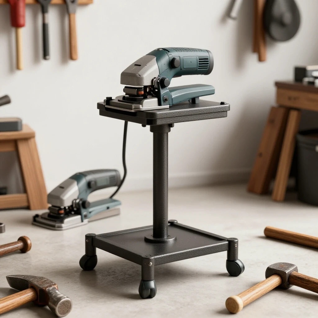
In this guide, I will walk you through the process of fabricating a heavy-duty, floor-anchored support system designed specifically for high-torque grinding equipment. We will focus on the technical realities of custom fabrication projects, including how to combat the inevitable metal warping that occurs when you strike an arc. If you have ever spent hours squaring up a frame only to watch it pull out of alignment during the final weld, this breakdown is for you. We are going to look at weld sequencing layout, accurate material prep, and structural damping to ensure your finished project stays exactly where you put it.
Planning the Foundation: Material Selection and Stability Requirements
Material selection involves choosing the correct steel profiles and thicknesses to handle the weight and vibration of industrial machinery. Selecting the right materials ensures the frame can absorb harmonic vibrations without flexing or shifting during heavy stock removal.
When you are planning a stationary tool support, mass is your best friend. For a standard 2×72 grinder, I recommend using 2×2 inch square tubing with a wall thickness of at least 3/16 inch, though 1/4 inch is even better for damping. Thinner wall tubing might be easier to cut, but it lacks the density required to kill vibration. For the base and top plates, 3/8-inch or 1/2-inch mild steel plate provides the necessary weight to keep the center of gravity low.
One of the most common mistakes I see in garage builds is using material that is too light. A grinder running at 5,000 surface feet per minute creates significant centrifugal force. If your stand is too light, that force turns into vibration. I always calculate the total weight of the stand to be at least 1.5 times the weight of the grinder itself. This ratio helps ensure that the machine’s energy is transferred into the floor rather than into the frame.
- Vertical Upright: 2x2x1/4″ Square Tubing.
- Base Plate: 12x12x1/2″ Steel Plate (for floor anchoring).
- Top Plate: 10x18x3/8″ Steel Plate (sized to your grinder’s mounting holes).
- Gussets: 3x3x1/4″ Flat Bar or Plate.
Accuracy Starts with the Cut: Kerf Allowances and Layout Precision
Layout precision is the process of marking and cutting metal to exact dimensions while accounting for the material lost during the cutting process. This “lost” material, known as the kerf, must be factored into every measurement to ensure the final assembly matches the blueprint.
In my early years, I couldn’t figure out why my frames were always 1/8 of an inch short. It turned out I wasn’t accounting for the kerf of my chop saw blade. If you are using an abrasive saw, that blade is literally eating an eighth of an inch of steel every time it passes through. To maintain a dimensional tolerance of +/- 1/16th inch, you must mark your lines and cut on the “waste side” of the line.
Metal Kerf Allowances by Cutter Type
| Cutting Tool | Typical Kerf Width | Best Use Case |
|---|---|---|
| Abrasive Chop Saw | 0.125″ (1/8″) | Rough structural cuts |
| Cold Saw | 0.090″ (3/32″) | Precision, cool-to-touch cuts |
| Portable Band Saw | 0.035″ – 0.042″ | Fine layout, low waste |
| Plasma Cutter | 0.040″ – 0.060″ | Plate shapes and gussets |
| Oxy-Acetylene Torch | 0.060″ – 0.100″ | Thick plate demolition |
When laying out your vertical uprights, use a machinist’s square and a carbide scriber rather than a sharpie. A sharpie line can be 1/16th of an inch wide on its own, which introduces immediate error. By using a fine scriber line, you have a precise target for your blade. I always double-check my “cut list” against the actual stock before I pull the trigger.
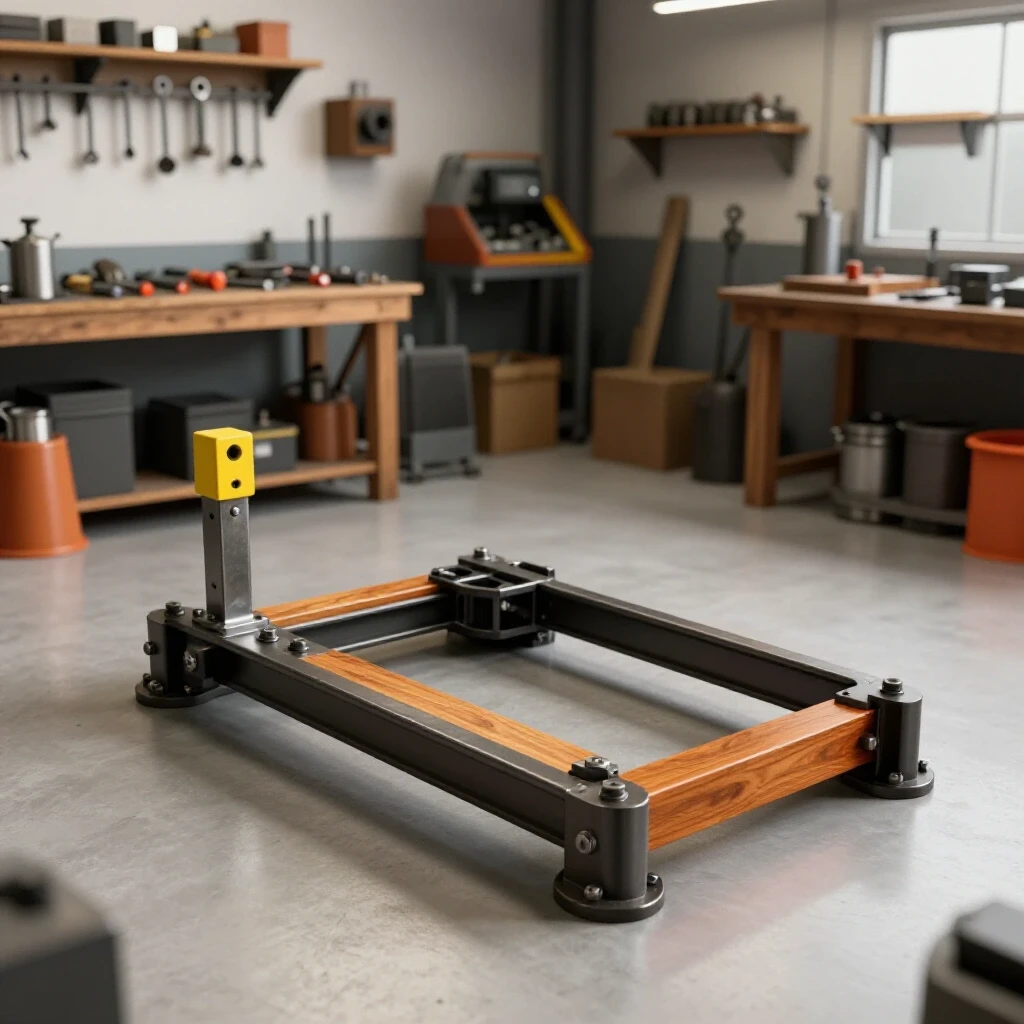
Building Workshop Jigs and Fixtures for Square Frames
Workshop jigs and fixtures are temporary or permanent tools used to hold workpieces in a fixed position during the fabrication process. They act as a physical constraint that prevents parts from moving while they are being tacked or welded.
You cannot trust your eyes to keep a 36-inch upright perfectly perpendicular to a base plate. To build a truly stable pedestal, you need a jig. I often use a piece of heavy-duty 3×3 angle iron clamped to my welding table as a “V-block” fixture. This keeps the square tubing aligned while I set the base plate.
If you don’t have a dedicated fixture table, you can create a “poor man’s jig” by tacking scrap blocks of steel to your workbench to create a 90-degree corner. This ensures that when you place your tubing and plate together, they are forced into alignment. Remember, metal moves when it gets hot. If you don’t restrain it with clamps and fixtures, it will pull toward the heat of the weld every single time.
- Clean your welding surface of all slag and debris.
- Clamp the base plate firmly to the table using at least four heavy-duty C-clamps.
- Use a magnetic square to hold the upright in place, but do not rely on it for the final weld.
- Verify squareness using the 3-4-5 triangle method or a high-quality framing square.
Structural Tacking: The Secret to Maintaining Alignment
Structural tacking involves placing small, temporary welds at key points to hold an assembly together before the final welding passes. These tacks must be strong enough to resist the initial cooling forces of the metal but small enough to be easily adjusted if needed.
Tack welding is where most custom fabrication projects succeed or fail. A common rookie mistake is to put one big tack on one side of a joint. As that tack cools, it shrinks, pulling the upright out of square. Instead, I use a “four-point” tacking strategy. I place a small tack (about 1/4 inch long) on the center of one side, then immediately place another on the exact opposite side.
Once the first two tacks are set, I re-check the square. If the upright has leaned, I can usually give it a firm tap with a dead-blow hammer to bring it back. Only after the piece is perfectly square in both the X and Y axes do I place the remaining two tacks. For a 2×2 inch upright, four tacks are mandatory. If you only tack two sides, the heat from the final weld will pull the metal toward the untacked sides, ruining your layout.
- Tack Size: 1/4″ to 3/8″ in length.
- Placement: Centered on each flat face of the tubing.
- Verification: Check squareness after every two tacks.
Why Weld Shrinkage Warps Square Structures—And the Precise Order to Lay Your Beads
Weld shrinkage is the physical contraction of metal as it cools from a molten state to room temperature. This contraction exerts massive force on the surrounding structure, often causing the metal to bend or “warp” toward the side of the weld bead.
When you lay a bead of weld, you are essentially casting a small piece of molten steel into a joint. As it cools, it shrinks by about 1% to 3% in volume. This might not sound like much, but across a 2-inch joint, it creates enough force to bend 1/4-inch steel. This is known as angular distortion. To combat this, you must use a specific weld sequencing layout.
Instead of welding all the way around the tube in one go, I weld in “stiches.” I’ll run a bead on the front face, then move to the back face. This balances the “pull” of the cooling metal. If you weld the front and then the side, the piece will pull diagonally. By welding opposite sides in sequence, the forces cancel each other out.
Weld Sequencing and Distortion Control
| Step | Action | Purpose |
|---|---|---|
| 1 | Tack all 4 sides | Initial alignment and restraint |
| 2 | Weld Side A (Front) | Primary structural bond |
| 3 | Weld Side C (Back) | Counteracts the pull from Side A |
| 4 | Allow to cool | Reduces cumulative heat buildup |
| 5 | Weld Side B (Left) | Lateral stabilization |
| 6 | Weld Side D (Right) | Counteracts the pull from Side B |
I also recommend “back-stepping” your welds. This means starting your bead an inch away from the corner and welding toward the corner, rather than starting at the corner and welding away. This technique helps distribute the heat more evenly and reduces the tendency of the metal to “flare” at the ends of the joint.
Vibration Damping and Floor Anchoring for High-Torque Tools
Floor anchoring is the process of permanently securing a machine stand to a concrete slab using mechanical or chemical fasteners. Vibration damping involves using specialized materials, like rubber or urethane, to absorb the energy generated by the machine’s motor and belt.
Once your stand is welded and square, the final step for a stationary installation is securing it to the garage floor. A 2×72 grinder produces high-frequency vibrations that can loosen bolts over time. To prevent this, I never bolt steel directly to concrete. Instead, I use 1/4-inch thick industrial rubber isolation pads between the base plate and the floor.
For the actual anchoring, 3/8-inch diameter wedge anchors are the standard. You’ll need a hammer drill and a masonry bit to set these into the concrete. I typically drill the holes in the base plate to 1/2 inch to allow for a small amount of adjustment. When you tighten the nuts, the wedge anchor expands into the concrete, creating a permanent bond. The combination of the heavy steel frame, the rubber pads, and the floor anchors will make your grinder feel like it’s part of the foundation of the house.
- Position the stand in its final location.
- Mark the hole locations on the concrete through the base plate.
- Move the stand and drill the holes to the depth specified by the anchor manufacturer.
- Vacuum out the dust from the holes (crucial for anchor grip).
- Place the rubber pads, set the stand back down, and drive the anchors in.
- Tighten the nuts until the rubber pads show about 10% compression.
Troubleshooting and Correcting Heat Distortion
Heat distortion correction is the act of returning a warped metal part to its intended shape using mechanical force or controlled heat application. Even with perfect sequencing, some minor movement is common in custom fabrication projects.
If you finish your stand and find that the top plate is tilted by 1/8th of an inch, don’t panic. This is a common reality of working with heat. One method I use to correct this is “flame straightening,” though it requires a delicate touch. By heating the side opposite the warp with an oxy-acetylene torch and then cooling it quickly with a wet rag, you can force the metal to shrink and pull the structure back into alignment.
Another option is the use of a heavy-duty hydraulic jack or a “port-a-power.” If the upright has leaned, you can brace the base against a wall and use the jack to gently push the top plate back to square. Since we are working within the elastic limit of the steel, you often have to push it slightly past square so that it “springs back” to the correct position. Always measure twice during this process; it is easy to overcorrect and end up with a wobble in the opposite direction.
- Mechanical Correction: Use a 20-ton press or hydraulic jack for thick-walled tubing.
- Thermal Correction: Heat the “high” side of the warp to a dull red and quench with water.
- Prevention: Increase the size of your tack welds if you notice significant movement during the first pass.
Actionable Tracking Framework: The Build Log
To ensure your project stays on track and within budget, I recommend keeping a simple build log. This helps you identify where errors occurred so you can avoid them on your next workshop fixture.
- Material Cost Tracking: Record the price per foot of your steel. In today’s market, prices fluctuate wildly.
- Cut List Verification: Check off each piece as it is cut and deburred.
- Weld Sequence Map: Literally draw a bird’s-eye view of your joints and number the order in which you will weld them.
- Tolerance Log: Measure the squareness before tacking, after tacking, and after final welding.
By documenting these metrics, you turn a weekend project into a data-driven fabrication exercise. This is how you transition from a “backyard builder” to a precision fabricator.
Final Assembly and Testing
Once the stand is anchored and the grinder is mounted, it’s time for the “nickel test.” Place a nickel on edge on the grinder’s work rest and turn the machine on. If the stand is built correctly—with sufficient mass, proper weld sequencing, and solid floor anchoring—the nickel should remain standing.
If it falls over immediately, check your mounting bolts. Often, vibration isn’t coming from the stand itself but from a slightly loose motor mount or an imbalanced tracking wheel. Because you built a rigid, stationary frame, you now have a stable platform that allows you to isolate and fix those machine-specific issues.
Building a high-quality tool support is about more than just having a place to put your grinder. It’s about creating a safer, quieter, and more accurate workspace. By following these steps—from kerf-aware cutting to strategic weld sequencing—you ensure that your custom fabrication projects result in professional-grade equipment that will last for decades.
FAQ: Common Questions About Building Heavy-Duty Tool Stands
How do I prevent the base plate from bowing when I weld the upright to it? Base plate bowing is caused by the weld pulling the center of the plate upward. To prevent this, clamp the base plate to a thick welding table or a piece of heavy I-beam before welding. Leave it clamped until the metal is completely cool to the touch.
Can I use a flux-core welder for this project, or do I need MIG? Flux-core is perfectly fine for structural stands. In fact, it often provides better penetration on thicker 1/4-inch material. Just be sure to clean the slag thoroughly between passes, especially if you are doing multi-pass welds on the base plate.
What is the ideal height for a belt grinder stand? The “standard” height is usually such that the contact wheel or platen is at elbow height. For most builders, this means the top of the stand should be between 34 and 38 inches. Measure your own comfortable working height before cutting your vertical upright.
Why shouldn’t I just use a heavy wooden post? Wood lacks the mass and rigidity of steel. Over time, the vibrations from the motor will compress the wood fibers around the mounting bolts, leading to a loose, unstable machine. Steel provides a permanent, non-compressible connection to the floor.
Do I really need to anchor it to the floor? If you want to do precision grinding or heavy profiling, yes. A free-standing stand will still vibrate and “hum.” Anchoring it to the concrete slab turns the entire floor into a giant heat sink and vibration dampener.
Is 1/4-inch wall tubing overkill? In the world of vibration damping, there is no such thing as overkill. Thicker walls mean more mass, and more mass means a smoother-running machine. If you have the budget and the ability to cut it, 1/4-inch is the gold standard.
How do I deal with a garage floor that isn’t level? Use steel shims under the base plate before you tighten your anchors. Place the shims as close to the anchor bolts as possible to prevent the base plate from flexing when you torque the nuts down.
What should I do if my welds are cracking? Cracking is usually a sign of poor penetration or “cold lapping” on thick plate. Ensure you are using enough voltage and that you have pre-heated the 1/2-inch base plate slightly with a torch to ensure the weld puddle fuses deeply into the thick steel.
Can I use a round pipe instead of square tubing? You can, but square tubing is much easier to layout and square up. Pipe requires specialized “notching” to fit flush against flat plates, whereas square tubing can be cut at simple 90-degree angles.
How often should I check the anchor bolts? Check them after the first 10 hours of use. The initial vibrations can sometimes settle the rubber pads, requiring a quarter-turn of the nuts to maintain full tension. After that, once a year is usually sufficient.
(This article was written by one of our staff writers, Robert Kline. Visit our Meet the Team page to learn more about the author and their expertise.)