How to Build a Sturdy Steel Gantry Crane Hoist Frame (Plan)
I have spent thirteen years in fabrication shops, and I have learned one thing the hard way: steel has a mind of its own. You can spend hours measuring, marking, and cutting your stock to the exact sixteenth of an inch. But the moment you pull the trigger on that MIG gun, the heat begins to fight you. I remember building my first heavy-duty lifting frame for a shop project. I had everything clamped down tight, or so I thought. By the time I finished the final pass on the base legs, the entire structure had twisted nearly half an inch. It didn’t sit flat, and it certainly wasn’t square. That project taught me that custom fabrication projects are not just about joining metal; they are about managing heat and forces.
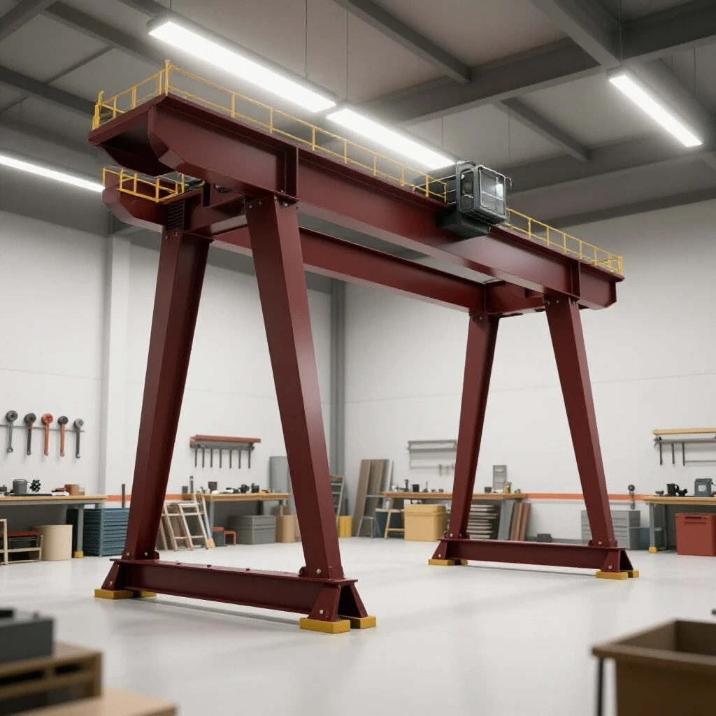
Designing a mobile lifting frame requires a deep understanding of how metal behaves under stress and heat. Whether you are building a rolling hoist for engine swaps or moving heavy machinery, the goal is a structure that remains plumb and true. This guide focuses on the practical side of fabrication. We will look at how to plan your cuts, set up workshop jigs and fixtures, and use a specific weld sequencing layout to keep your project straight.
Designing the Framework and Calculating Kerf Allowances
Planning is the stage where most errors are born. A good build starts with a clear understanding of your materials and how your tools will interact with them. For a workshop lifting frame, we usually look at rectangular tubing for the uprights and channel sections for the base or reinforcement.
Kerf is the width of the material removed by your cutting tool. If you use a standard abrasive chop saw, your kerf might be 1/8 inch. If you use a cold saw or a bandsaw, it might be 1/16 inch. If you have ten cuts to make and you don’t account for a 1/8-inch kerf, your final assembly will be over an inch short. I always mark my “keep” side and my “waste” side clearly with a soapstone or a scribe.
Why Material Selection Dictates Stability
Material selection is about more than just strength; it is about how the metal handles the welding process. Rectangular tubing offers great torsional rigidity, which means it resists twisting. Channel steel is excellent for bases because it provides a flat surface for mounting casters and resists bending along its primary axis.
When you choose your steel, look for “mill scale” consistency. Heavy mill scale can interfere with your ground and your weld puddle. I prefer to grind back the scale at least one inch from every joint. This ensures a clean path for the arc and reduces the chances of porosity, which can weaken a structural joint.
| Cutter Type | Typical Kerf Width | Accuracy Level | Best Use Case |
|---|---|---|---|
| Abrasive Chop Saw | 1/8″ – 5/32″ | Moderate | Rough cuts for base frames |
| Portable Bandsaw | 1/16″ – 3/32″ | High | Uprights and precise angles |
| Plasma Cutter | 1/16″ – 1/8″ | Variable | Custom gussets and plates |
| Cold Saw | 1/32″ – 1/16″ | Very High | Critical fit-ups for squareness |
Building Workshop Jigs and Layout Fixtures
A layout fixture is a temporary structure or tool used to hold workpieces in the exact position they need to be during assembly. Think of it as a second set of hands that never gets tired and never moves. For a large frame, you cannot rely on a standard welding table alone. You often need to create floor jigs using scrap angle iron or heavy-duty clamps.
I like to use the “3-4-5 rule” to ensure my base is square. If one side is 3 feet and the other is 4 feet, the diagonal must be 5 feet. If those numbers don’t match, your frame is a trapezoid, not a rectangle. Using workshop jigs and fixtures like corner magnets and heavy C-clamps helps maintain these dimensions while you apply your first tacks.
Creating a Level Working Plane
In a garage, the floor is rarely perfectly flat. If you build a frame on a sloped floor, the frame will likely end up with a “wind” or a twist. I use adjustable jack stands or steel shims to create a level plane before I ever start tacking.
Metal layout tips often overlook the importance of the “reference edge.” Always measure from the same end of the tube for every mark. If you measure from the left side for one hole and the right side for another, any slight variation in the total length of the tube will throw off your alignment.
Controlling Metal Warping with Strategic Tacking
Tack welds are small, temporary welds that hold the pieces in place before the final beads are laid. Many builders make the mistake of using tacks that are too small. A weak tack will snap as the metal cools and shrinks, throwing your whole frame out of alignment.
For a structural lifting frame, I recommend “bridge tacks.” These are tacks that span the gap of the joint and are thick enough to resist the pull of the metal. I usually place tacks at the corners first, then check for squareness. If the frame has pulled, I can often “cold-set” it (bend it back) before the tacks get too heavy.
The Physics of Angular Weld Shrinkage
When you weld a joint, the liquid metal occupies more volume than the solid metal. As it cools, it contracts. This is called angular shrinkage. If you weld only one side of a T-joint, the upright will pull toward the side of the weld.
To combat this, I use a “staggered tacking” method. I place a tack on one side, then immediately place one on the opposite side. This balances the tension. I also “pre-set” my joints by a degree or two in the opposite direction of the expected pull. By the time the weld cools, the shrinkage pulls the part right into the square position.
- Tack Size: Aim for a tack that is roughly 2 to 3 times the thickness of your welding wire.
- Tack Spacing: For long spans of rectangular tubing, place a tack every 6 to 8 inches to maintain the gap.
- Check and Re-check: Always use a framing square after every four tacks. It is easier to grind out a tack than a full bead.
Executing the Weld Sequencing Layout
Weld sequencing is the specific order in which you lay your beads to minimize distortion. If you start at one end of a gantry beam and weld all the way to the other, the heat build-up will cause the beam to bow like a banana. This is one of the most common metal warping solutions that professional fabricators use.
I use a “back-stepping” or “skip welding” technique. Instead of one long continuous bead, I weld short segments in different areas of the frame. This allows the heat to dissipate more evenly across the entire structure.
Balancing Heat Input
When welding the uprights to the base, I never finish one joint completely before moving to the next. I do the inside corners of all four joints first. Then I move to the outside corners. This “criss-cross” pattern ensures that the pulling forces on the left side of the frame are neutralized by the pulling forces on the right side.
| Weld Type | Pull Direction | Mitigation Strategy |
|---|---|---|
| Fillet Weld (T-Joint) | Toward the weld toe | Pre-bend part 1-2 degrees away |
| Butt Weld (Flat) | Longitudinal shrinkage | Use heavy clamps and back-stepping |
| Lap Joint | Twisting/Warping | Tack both ends and center before welding |
| Corner Weld | Pulls inward | Use a 90-degree jig and external bracing |
Structural Reinforcement and Bolted Connections
In a mobile lifting frame, the top beam is often a point of high stress. While welding is great for permanent joints, bolted connections are often better for the main crossbeam. This allows you to disassemble the frame for transport or storage. It also prevents the heat of a massive weld from warping the most critical part of the hoist.
I use gussets—triangular pieces of plate steel—to reinforce the corners where the uprights meet the base. A gusset increases the surface area of the joint and distributes the load over a larger section of the tubing. When welding gussets, I follow the same sequencing rules: tack all corners, then weld in short bursts.
Caster Integration and Base Alignment
The mobility of your frame depends on how well the casters are aligned. If the mounting plates are welded on crooked, the frame will “dog-track” or be difficult to push. I prefer to bolt my casters to a pre-welded mounting plate.
When welding the mounting plates to the channel steel base, the heat can cause the plate to cup. To prevent this, I clamp the mounting plate to a thick piece of scrap copper or a heavy steel block. This acts as a heat sink, drawing the temperature away from the plate and keeping it flat.
- Layout the base: Ensure the channel sections are parallel.
- Tack the mounting plates: Use four heavy tacks on the corners of each plate.
- Weld the plates: Use a skip-welding sequence, moving from the front-left caster to the back-right caster.
- Drill the holes: I prefer to drill caster holes after welding the plates to ensure they haven’t shifted during the heating process.
Correcting Heat Distortion and Final Squaring
Even with the best planning, some warping is inevitable. In the prototype world, we call this “finessing” the build. If a leg is slightly out of plumb, you can use “heat shrinking” to pull it back. This involves heating a small spot on the side opposite the warp with a torch and then cooling it quickly with water or compressed air. The rapid contraction pulls the metal back toward the heat source.
However, heat shrinking should be a last resort. It is much better to use mechanical force. I often use a heavy-duty ratchet strap or a hydraulic jack to “tweak” a frame back into square while it is still warm from welding. This is why having a solid anchor point in your shop, like a heavy welding table or a floor-mounted D-ring, is so valuable.
Post-Weld Inspection Benchmarks
Once the frame is cool to the touch, I perform a final inspection. I check the “plumb” of the uprights using a level and the “square” of the base using the diagonal measurement method again. If the diagonals are within 1/16 of an inch, I consider that a success for a manual fabrication project.
- Dimensional Tolerance: Aim for +/- 1/16 inch on all major spans.
- Angular Tolerance: Keep uprights within 0.5 degrees of vertical.
- Flatness: Ensure all four caster plates sit on the same plane to avoid “wobble.”
Practical Tracking Framework for the Build
To stay organized, I use a build log. This helps me keep track of which joints have been tacked and which have been fully welded. In a complex project like a lifting frame, it is easy to forget a single underside weld that could compromise the structure.
The 10-Step Fabrication Checklist
- Cut List Verification: Double-check all lengths against your plan, accounting for kerf.
- Deburring: Remove all burrs and mill scale from joint areas.
- Base Layout: Secure the base channel on a level surface using jigs.
- Initial Tacking: Place bridge tacks on the base frame and check diagonals.
- Upright Alignment: Use a magnetic level and corner clamps to position uprights.
- Gusset Placement: Tack all reinforcement gussets into position.
- Sequence Welding: Execute the skip-welding pattern, starting from the center and moving out.
- Cooling Period: Allow the frame to air-cool; do not quench structural welds with water.
- Caster Mounting: Attach casters and check for smooth movement.
- Final Straightening: Use mechanical force or heat shrinking to correct any minor warps.
Summary of Best Practices
Building a sturdy steel lifting frame is a test of your layout and heat management skills. By focusing on accurate square cuts and using workshop jigs and fixtures, you set a foundation for success. Remember that weld sequencing layout is your primary tool for fighting distortion. Don’t rush the process. A frame that is welded slowly and in the correct order will always be stronger and straighter than one that is rushed.
Always prioritize clean metal and solid tacks. If your tacks are holding, your frame has a much better chance of surviving the massive shrinkage forces that occur during the final welding passes. Take your time with the layout, respect the heat, and you will end up with a utility project that serves your shop for decades.
FAQ: Common Questions About Building Steel Frames
How do I stop my rectangular tubing from twisting when I weld it?
Twisting usually happens because of uneven heat. To stop this, use a “balanced” welding sequence. If you weld the top of the tube, weld the bottom next. Never weld all four sides of a joint in a circular motion. Instead, weld opposite sides to cancel out the pulling forces.
What is the best way to ensure my uprights stay perfectly vertical?
Use a combination of a framing square and a plumb bob or a high-quality level. Clamp the upright to a heavy “strongback” or a vertical jig. Tack the upright on all four sides before doing any full welds. If it leans, you can still tap it back into place.
Should I use MIG or Stick welding for a shop lifting frame?
MIG welding is excellent for custom fabrication projects because it is fast and produces less overall heat input if used correctly. However, Stick welding is often better for thick channel steel because it provides deeper penetration. For most garage builds using 3/16″ or 1/4″ wall tubing, a 220V MIG welder is the standard choice.
How much gap should I leave between pieces for a good weld?
For structural joints, a “root gap” of about 1/16 to 3/32 inch is often recommended. This allows the weld to penetrate through the full thickness of the metal. If the pieces are touching too tightly, the weld might just sit on the surface, which is much weaker.
Why did my frame warp even though I used clamps?
Clamps can only do so much. Metal shrinks with thousands of pounds of force as it cools. If you remove the clamps while the metal is still hot, it will pull. Always leave your clamps on until the joint is cool to the touch. Also, ensure your clamps are attached to something much stiffer than the part you are welding.
Can I use a regular tape measure for high-accuracy layouts?
Yes, but you must be consistent. Use the same tape measure for the whole project. Many fabricators “burn an inch,” meaning they start their measurement at the 1-inch mark instead of the hook at the end. This avoids the slight play that most tape measure hooks have.
How do I calculate the weight of the steel for my plan?
Steel weights are standard. For example, rectangular tubing weight is usually listed in pounds per foot. You can find charts online for “lbs per foot” of various sizes. Knowing the total weight helps you choose the right casters and ensures you can safely move the frame once it is finished.
What is the most common mistake in gantry-style builds?
The most common mistake is failing to account for “racking.” This is when the frame leans to the side under a load. You prevent this by using large, well-welded gussets and ensuring your upright-to-base connection is as rigid as possible. Avoid relying on the strength of the weld alone; use geometry (like triangles) to provide stability.
Is it better to weld or bolt the reinforcement gussets?
Welding gussets is generally better because it creates a monolithic structure that resists vibration and shifting. However, make sure you don’t over-weld them. A continuous bead all the way around a gusset can actually weaken the main tube by creating a “heat-affected zone” that acts like a perforated line. Staggered welds are often sufficient.
How do I fix a base that doesn’t sit flat on all four casters?
If one caster is “floating,” the base has a twist. You can sometimes fix this by cutting a small slit in one of the base members, bending it until the frame sits flat, and then welding the slit shut. This is a common field-fix in fabrication, but it requires careful re-welding to maintain strength.
(This article was written by one of our staff writers, Robert Kline. Visit our Meet the Team page to learn more about the author and their expertise.)