How to Calibrate and Upgrade a CNC Plasma Table (DIY Fix)
I remember the specific Tuesday afternoon when my shop hit a wall. I had a stack of customer orders for custom brackets, a CNC table that was cutting slightly out of square, and a floor layout that required me to move a heavy welding table just to load a fresh sheet of 10-gauge steel. It was the “messy middle” of scaling—too big to be a hobbyist, but not yet efficient enough to feel like a professional operation. Over the last 20 years, I have learned that moving from a basic setup to a high-output manufacturing cell isn’t about buying the most expensive gear. It is about the systematic refinement of the tools you already own and the space they occupy.
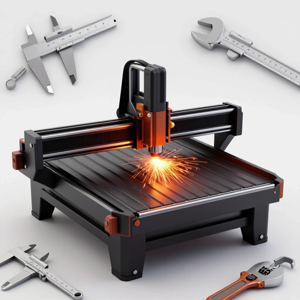
When we talk about improving a motion-control cutting system, we are really talking about the intersection of physics and logic. If your rails are not perfectly parallel, or if your motor signals are “noisy,” no amount of high-end software will save your parts. My background in manufacturing operations has taught me that a shop is a living organism. If the “arteries”—your material flow and power delivery—are clogged, the “heart” of the shop, which is your CNC machinery, will eventually fail.
Mapping the Path of Steel: Workflow and Layout Physics
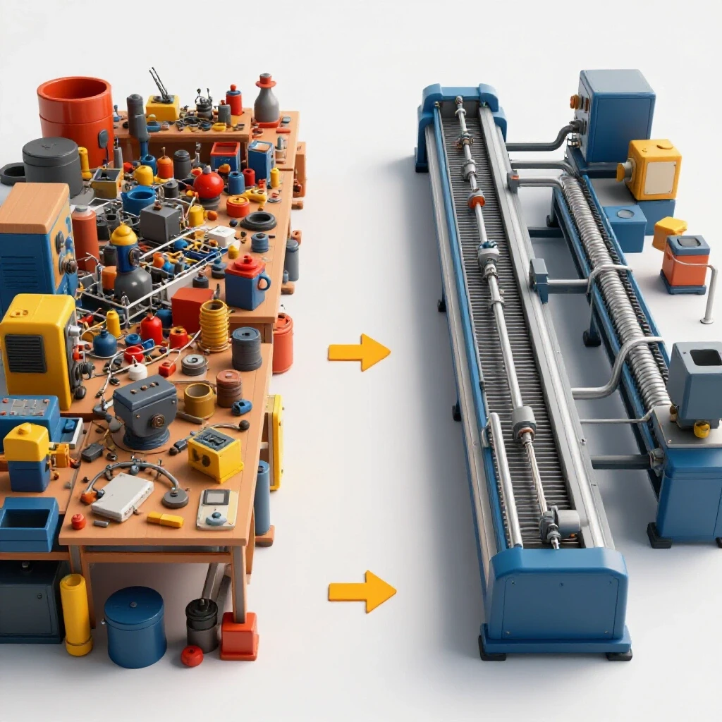
An advanced workshop layout is the foundation of every profitable cut. In my early years, I treated my shop like a storage unit with a few tools scattered inside. This led to “spaghetti workflow,” where I walked miles every day just moving parts from the cutter to the grinder. To fix this, you must analyze your floor load ratings and material travel paths.
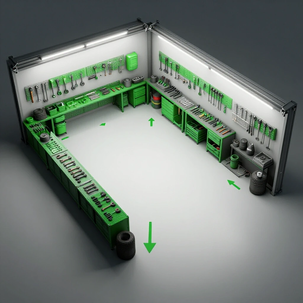
A professional layout follows a linear or “U-shaped” flow. Raw material enters at one point, moves to the cutting station, proceeds to secondary operations like deburring or bending, and exits through shipping. I recommend maintaining a 3-foot minimum access zone around all sides of your cutting table. This isn’t just for safety; it is for maintenance. If you have to crawl over a water tray to adjust a limit switch, you simply won’t do it as often as you should.
| Layout Feature | Hobbyist Setup | Advanced Manufacturing Cell |
|---|---|---|
| Material Path | Obstructed/Random | Linear/Unimpeded |
| Machine Access | One side only | 360-degree (3-ft clearance) |
| Floor Load | Standard garage slab | Reinforced 4-6″ 4000 PSI concrete |
| Zoning | Mixed (Grinding near CNC) | Isolated (Dirty vs. Clean zones) |
Power Infrastructure: Balancing the Load
Integrating automation often requires more than a standard 220V dryer outlet. As you scale, you will likely encounter equipment designed for 3-phase power. In a home-based or light commercial setting, this usually means installing a rotary phase converter (RPC) or a digital phase shifter.
I prefer rotary converters for their ability to handle the high-inrush current of large air compressors and motors. However, you must monitor your phase balance. If the voltage between your three lines varies by more than 5%, you risk overheating your motors. I use a basic multimeter to check the “manufactured leg” under load. If the voltage is too high, it can fry sensitive control electronics; if it is too low, the motor will lose torque.
- Rotary Phase Converter: Best for high-torque starts and multiple machines.
- Static Converter: Only for light loads; reduces motor horsepower by a third.
- VFD (Variable Frequency Drive): Excellent for single-motor control but requires technical setup.
Designing High-Volume Clean Air Filtration
Air quality is the silent killer of CNC plasma precision. Most fabricators focus on the torch, but the air supply is what actually does the work. If your air contains moisture or oil, your consumables will fail in minutes rather than hours. I recommend a multi-stage approach: a refrigerated air dryer followed by a 0.01-micron coalescing filter.
For fume extraction, you need to calculate your CFM (Cubic Feet per Minute) requirements based on the surface area of your table. For a 4×8 table, I aim for at least 1,500 to 2,000 CFM of extraction. If you are building a DIY water table, ensure the water level is within 1 inch of the material to trap the maximum amount of dross and particulates.
- Stage 1: Standard water trap at the compressor tank.
- Stage 2: Refrigerated dryer to drop the dew point.
- Stage 3: Desiccant or coalescing filter at the machine’s air inlet.
- Stage 4: Final regulator to maintain a steady 90–120 PSI during the cut.
Mechanical Precision: Squaring and Leveling the Gantry
A CNC table is only as accurate as its frame. Over time, vibrations and heavy material loading can knock a gantry out of square. To perform a manual alignment, I use the “3-4-5 triangle” method. Measure 3 feet down one rail, 4 feet across the gantry, and the diagonal should be exactly 5 feet. Even a 1/16th-inch error over four feet will result in parts that don’t fit together during assembly.
Leveling is equally critical. Use a machinist’s level—not a standard carpenter’s level—to ensure the rails are co-planar. If one rail is higher than the other, the gantry will “crab” or bind as it moves. This creates friction that leads to lost steps in your motors. I check my table’s level every six months, especially if the shop undergoes significant temperature swings that might cause the concrete slab to shift.
Tuning the Motion System: Steps and Backlash
Once the frame is square, you must calibrate the “brain” of the machine. This involves setting the “steps per unit” in your control software. I place a high-quality steel rule on the table and command the machine to move exactly 10 inches. If it moves 10.05 inches, I use a simple formula: (Commanded Distance / Actual Distance) * Current Steps = New Steps.
Backlash is another common bottleneck. This is the “play” or “slop” in the gears or lead screws. You can test this by mounting a dial indicator against the gantry and moving it back and forth by 0.001 inches. If the motor turns but the gantry doesn’t move, you have mechanical backlash. Sometimes this can be fixed by tightening a drive belt or adjusting the tension on a rack-and-pinion gear. In other cases, you may need to enable “backlash compensation” in your software, though a mechanical fix is always superior.
Optimizing Torch Height Control (THC)
The Torch Height Control (THC) is what separates a hobbyist cut from a professional one. It measures the voltage of the plasma arc to maintain a consistent distance between the tip and the metal. If the metal warps from heat, the THC moves the torch up or down in real-time.
I often find that “diving” torches are caused by incorrect “voltage sampling.” If your machine slows down for a corner, the arc voltage changes, and the THC might think the torch is too high, causing it to dive into the plate. To fix this, I adjust the “anti-dive” settings in my CAM software or increase the sensitivity of the voltage feedback loop.
- Target Tip Volts: Typically between 90V and 140V depending on material thickness.
- Pierce Height: Usually 1.5 to 2 times the cutting height to protect the shield cap.
- Cut Height: Generally 0.06 inches (1.5mm) for most mild steel applications.
Software and CAD/CAM Integration Strategies
Efficiency isn’t just about how fast the machine moves; it’s about how fast you can go from an idea to a finished part. Advanced shop owners should look into “nesting” software. This allows you to fit as many parts as possible onto a single sheet of steel, reducing waste. I have seen shops save 15% on material costs simply by switching to a more intelligent nesting algorithm.
Building a “tool library” is another professional move. Instead of guessing the settings for 1/4-inch plate every time, I have a verified list of feed rates, pierce delays, and voltages saved in my CAM software. This eliminates the “trial and error” phase of a project, which is where most shop time is wasted.
Troubleshooting Common Motion Errors
| Symptom | Probable Cause | DIY Fix |
|---|---|---|
| Oval-shaped circles | Loose drive belt or gantry out of square | Tighten belts; re-square using 3-4-5 method |
| Jagged cut edges | Vibration or loose torch mount | Check for mechanical play; ensure slats are secure |
| Dross on bottom of cut | Feed rate too slow or low air pressure | Increase speed; check air filters for clogs |
| Torch dives into plate | THC voltage set too high or moisture in air | Lower target voltage; drain air compressor |
Tracking Performance: The Shop Audit
To move from a hobby to a professional operation, you need data. I keep a logbook next to my CNC table. I track the number of pierces on each set of consumables and the total “arc-on” time for each project. This data allows me to calculate my true overhead. If I know a set of electrodes lasts for 300 pierces, I can price my jobs accurately and avoid running out of parts in the middle of a rush order.
I also perform a “static pressure” check on my dust collection every month. If the suction at the table drops below my baseline, I know a filter is getting clogged or a duct has a leak. These small, proactive steps prevent the catastrophic failures that lead to expensive downtime.
Practical Maintenance Checklist
- Daily: Drain the air compressor and check the moisture traps.
- Weekly: Wipe down the rails with a dry lubricant (avoid oil, as it attracts dust).
- Monthly: Check gantry squareness and belt tension.
- Quarterly: Inspect all electrical connections for signs of heat or arcing.
- Annually: Re-level the table and update control firmware.
Transitioning to a Semi-Professional Operation
The jump to a professional-grade workshop is often more mental than physical. It requires you to stop viewing your shop as a collection of tools and start seeing it as a production system. When I stopped “fixing” things on the fly and started “calibrating” them on a schedule, my scrap rate dropped by 20%.
Focus on the basics: clean power, dry air, and a square frame. Once those are locked in, the automation becomes a tool for growth rather than a source of frustration. Your goal is a shop where the machine does exactly what it is told, every single time, allowing you to focus on design and business development rather than troubleshooting.
Frequently Asked Questions
How do I know if my stepper motors are losing steps? You will notice that the torch does not return to the “home” position accurately after a cut. This is often caused by mechanical binding, excessive acceleration settings in your software, or electrical interference (EMI) from the plasma power source.
What is the most common cause of poor cut quality? In 90% of cases, it is either moisture in the air lines or worn-out consumables. Even a tiny amount of water will distort the plasma arc, leading to beveling and excessive dross. Always check your air filters first.
Can I run a CNC plasma table on a 100-amp sub-panel? Yes, but you have to manage your loads. A plasma cutter and a large air compressor running simultaneously can easily pull 60-80 amps. If you add lights, fans, and a computer, you are near the limit. I recommend a dedicated 100-amp panel for the shop area alone.
How often should I replace my table slats? Slats should be replaced when they are so notched or covered in dross that the material no longer sits flat. An unlevel workpiece will confuse your THC and lead to inconsistent cuts. Many pros flip their slats halfway through their lifespan to get more use out of them.
What is “Backlash” and why does it matter? Backlash is the tiny gap between gear teeth or screw threads. When the motor reverses direction, it has to move through that gap before the table actually starts moving. In CNC work, this causes flat spots on circles and prevents parts from being dimensionally accurate.
Is a water table better than a downdraft system? Water tables are cheaper to build and very effective at catching sparks and heavy dust. However, they can cause “splash-back” on the bottom of parts. Downdraft systems provide cleaner cuts but require high-powered fans (2,000+ CFM) and expensive ducting to vent outside.
How do I reduce electrical noise (EMI) in my CNC setup? Use shielded cables for all your motor and sensor lines. Ensure the shield is grounded at only one end (the controller end) to avoid ground loops. Keep your plasma torch lead as far away from the computer and motor cables as possible.
What is the ideal “Pierce Delay”? The pierce delay is the time the torch stays stationary while the arc punches through the metal. If it’s too short, the torch moves before the hole is through, breaking the tip. If it’s too long, it creates a large, ugly hole. For 1/4-inch steel, a delay of 0.5 to 0.8 seconds is typical.
Should I use servos or stepper motors? Steppers are great for most small to mid-sized shops because they are affordable and simple. Servos are faster and have “closed-loop” feedback, meaning they know if they have missed a step, but they are more expensive and complex to tune.
How do I square a gantry without expensive lasers? Use the 3-4-5 rule or the “diagonal measurement” method. Measure from the front-left corner to the back-right corner, then from the front-right to the back-left. If the two diagonal measurements are identical, your table is square.
Why is my plasma arc “flaming out” mid-cut? This is usually a sign of low air pressure at the torch or a loose work lead (ground clamp). Ensure your ground is clamped directly to the workpiece, not just to the table frame, for the best electrical connection.
How do I calculate my shop’s hourly rate? Add up your monthly overhead (rent, power, insurance, consumable budget) and divide by the number of hours you spend cutting. Then add your desired profit margin. Most semi-pro shops find their “break-even” rate is between $60 and $100 per hour.
(This article was written by one of our staff writers, Edward Sinclair. Visit our Meet the Team page to learn more about the author and their expertise.)