Pre-Weld Quality Checks for Structural Steel (Checklist)
Scaling a fabrication shop from a hobbyist space to a semi-professional operation is a major milestone. I remember the day I realized my original layout was costing me money. I was tripping over 20-foot sticks of tubing and spending more time hunting for a square than actually burning wire. Transitioning to a high-output environment requires more than just buying a CNC plasma table; it demands a systematic approach to how we handle material before the first bead is even laid.
In my two decades of managing shop flows, I have learned that the most expensive mistakes happen during the preparation phase. When you are scaling up, you move from “making it work” to “making it profitable.” This shift requires a focus on workflow optimization and rigorous verification of structural members before they ever reach the welding table. If your layout is cluttered or your power supply is unstable, your ability to perform accurate assessments of your steel will suffer, leading to rework and lost margins.
Mapping Material-Flow Loops for Inspection Efficiency
Material flow is the physical path a piece of steel takes from the delivery truck to the final shipping crate. In a professional shop, this path should be a logical, one-way loop that minimizes handling and allows for easy access to inspection tools at every stage of the process.
When I first integrated a CNC plasma system, I made the mistake of placing it in a corner. I had to crane-hoist every sheet over other machines just to check for surface defects. Now, I advocate for a linear flow. This means raw material enters at one end, moves through a cleaning and inspection station, proceeds to cutting, and finally lands at the assembly table. This layout ensures that you are checking for straightness, mill scale issues, and dimensional accuracy without fighting your own floor plan.
Why Back-and-Forth Foot Traffic Kills Shop Throughput
Excessive movement is a hidden cost that drains your energy and introduces errors into your preparation routine. If you have to walk 50 feet to grab a set of calipers to check a flange thickness, you are less likely to do it as often as you should.
I use a “Five-Step Rule” in my shop. Any tool needed for verifying the readiness of a joint must be within five steps of the workstation. By reducing the physical distance between your material and your measurement tools, you create a environment where quality checks become a natural part of the rhythm rather than a chore. This is especially critical when dealing with heavy structural steel where moving the material itself is a labor-intensive task.
| Layout Type | Material Travel Distance | Inspection Ease | Bottleneck Risk |
|---|---|---|---|
| Hobbyist (Station-Based) | High | Low | Very High |
| U-Shaped Flow | Moderate | High | Moderate |
| Linear (Industrial) | Low | Very High | Low |
Measuring Floor Capacities and Machine Spacing
Floor load ratings determine how much weight your shop floor can safely support without cracking or shifting, which can throw your machinery out of level. Structural steel is heavy, and concentrated loads from storage racks or large CNC tables can exceed standard residential garage slab limits.
Most residential slabs are 4 inches thick, rated for roughly 3,000 to 4,000 PSI. If you are installing a 5×10 CNC plasma table and a rack for I-beams, you must verify that your floor can handle the point loads. I always recommend a 3-foot minimum access zone around all machinery. This space isn’t just for safety; it provides the room necessary to use long straightedges and levels when checking the alignment of large structural components before they are tacked together.
Optimizing 3-Phase Power for Precision Preparation Tools
3-phase power is a type of electrical distribution that uses three alternating currents to provide more consistent and efficient energy to heavy machinery. Unlike standard single-phase power, it allows for smaller motors to produce more torque and keeps high-draw tools like industrial grinders and CNC systems running smoothly.
When I upgraded my shop, I faced the common hurdle of only having single-phase service. I had to decide between a Rotary Phase Converter (RPC) or Variable Frequency Drives (VFDs). A stable power supply is vital for the tools we use to prep steel. If your grinder bogs down because of voltage drops, you get an uneven surface finish on your bevels. If your CNC plasma’s height controller flickers due to poor power, your cut quality suffers, making your fit-up checks a nightmare.
Building Balanced 3-Phase Systems for High-Output Shops
A balanced system ensures that the voltage between all three legs of your power supply stays within a tight tolerance, usually plus or minus 5 percent. This balance is crucial for the longevity of your motors and the accuracy of your electronic controllers.
In my experience, a Rotary Phase Converter is the workhorse for a growing shop. It uses a large idler motor to generate the third leg of power. However, you must monitor the “manufactured leg” closely. If the voltage on that leg is too high or too low, it can damage sensitive CNC electronics. I installed a digital volt-meter on my main panel to track this. This ensures that when I am using a heavy-duty sander to remove mill scale, the tool maintains constant RPMs for a uniform, weld-ready surface.
- Rotary Phase Converter: Best for running multiple machines; robust but can be noisy.
- Variable Frequency Drive (VFD): Best for single machines; allows for speed control but requires individual installation.
- Digital Phase Converter: Most expensive; provides the cleanest power for sensitive CNC electronics.
Electrical Phase Loads and Machine Safety
Phase loading refers to how much current each leg of your electrical system is carrying at any given time. If one leg is overloaded while the others are light, you risk tripping breakers or overheating your equipment.
When I laid out my 3-phase network, I mapped out the peak draw of every tool, from the ironworker to the CNC table. I made sure to balance the loads so that the heavy preparation tools—like the large abrasive saws—didn’t starve the CNC controller of power. This technical discipline prevents mid-cut restarts. A failed cut on a structural beam isn’t just a waste of time; it creates a dimensional defect that might not be caught until you are trying to fit the joint together.
Designing High-Volume Air Filtration for Surface Preparation Zones
Air filtration systems use fans and filters to remove harmful dust, metal shavings, and fumes from the shop environment. In structural fabrication, the amount of dust generated by grinding mill scale and cleaning steel can quickly overwhelm a standard shop vacuum.
I learned the hard way that “good enough” ventilation isn’t enough when you scale up. I used to rely on an open garage door, but that didn’t stop fine metallic dust from settling on my precision measurement tools. Dust on a caliper or a laser level can lead to false readings. A high-volume air scrubbing system keeps the air clear and your surfaces clean, ensuring that when you check a joint for fit-up, you are seeing bare metal, not a layer of grime.
Installing Duct Networks and Managing Static Pressure
Static pressure is the resistance that air encounters as it moves through your ductwork. The more bends, long runs, or small-diameter pipes you have, the harder your dust collector has to work to move air.
To maintain 1,000 to 2,000 CFM (Cubic Feet per Minute) at the tool, I designed my ductwork using 6-inch smooth-walled pipe rather than flexible ribbed hose. I kept the runs as straight as possible. I also installed a multi-stage cyclone collector. This system drops the heavy metal chips into a bin before the fine dust reaches the filters. This setup is essential when you are prepping large batches of structural steel; it ensures your workspace remains clean enough for accurate visual inspections of the steel’s surface.
Commercial-Grade Air Scrubbing and OSHA Standards
OSHA (Occupational Safety and Health Administration) provides guidelines for air quality to protect workers from inhaling hazardous particles. While many home-based shops aren’t strictly regulated by OSHA, following their standards is a smart business move.
I aim for at least six air exchanges per hour in my shop. This means the total volume of air in the shop is filtered every ten minutes. Keeping the air clean protects your lungs, but it also protects the mechanical components of your CNC table. Grit and dust are abrasive. If they settle on your gantry rails, they cause premature wear, leading to “slop” in your cuts. This slop makes it impossible to achieve the tight tolerances required for high-quality structural joints.
- CFM Requirement: 1,000-1,200 CFM for general grinding; 1,500+ for CNC plasma tables.
- Filter Rating: Use MERV 13 or higher to capture fine metallic dust.
- Duct Material: Use 26-gauge snap-lock pipe or better; avoid PVC due to static build-up.
Integrating CNC Plasma Tables into the Structural Workflow
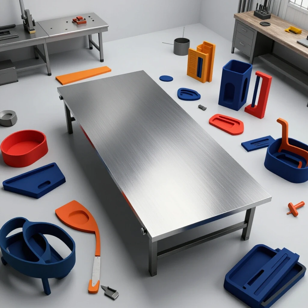
A CNC plasma table uses a computer-controlled torch to cut shapes out of metal with high precision. Integrating this into your workflow allows you to move from manual marking and cutting to a system where dimensions are verified in the software before the first spark is struck.
The transition to CNC was the biggest hurdle for my shop. I had to learn that the machine is only as good as its setup. If the gantry isn’t square or the slats aren’t level, every part it produces will be slightly off. This makes the initial inspection of your cut parts even more critical. You aren’t just checking the steel; you are checking the machine’s calibration.
Leveling CNC Plasma Lines and Configuring Tooling Files
Leveling a CNC table involves more than just a bubble level; it requires ensuring the entire frame is planar so the torch maintains a consistent distance from the material. This is known as torch height control (THC).
In my shop, I spent three days leveling my 5×10 table using a precision water level and a dial indicator. If the table is out of level, your bevel angles will vary across the length of a cut. When you go to verify the joint geometry before welding, you’ll find gaps that are impossible to fill consistently. I also spent time building a “tool library” in my CAM software. This library stores the exact speeds and feeds for different thicknesses of structural steel, ensuring that every cut has a clean edge that requires minimal prep.
Software CAD/CAM Integrations and Closed-Loop Feedback
CAD (Computer-Aided Design) is where you draw your parts, and CAM (Computer-Aided Manufacturing) is where you tell the machine how to cut them. Closed-loop feedback uses encoders to tell the computer exactly where the torch is at all times.
I highly recommend systems with servo motors and closed-loop feedback for structural work. Stepper motors can “lose steps” if they hit a piece of slag, which ruins the part’s dimensions. With a closed-loop system, if the torch gets bumped, the machine knows and stops. This level of automation means that when I pull a gusset plate off the table, I already know the dimensions are within 0.010 inches. This drastically reduces the time I spend with a tape measure during the final fit-up check.
The Systematic Pre-Assembly Inspection Protocol
A systematic inspection protocol is a set of repeatable steps used to verify that every piece of steel is ready for welding. This involves checking for material defects, verifying dimensions, and ensuring the joint surfaces are properly prepared.
In my operation, this is the “Go/No-Go” stage. We don’t start the welder until the checklist is complete. This discipline prevents the “I’ll fix it in the weld” mentality, which is the death of productivity. By catching a lamination in the steel or an incorrect bevel angle now, you save hours of grinding and re-welding later.
Visual Verification of Structural Members
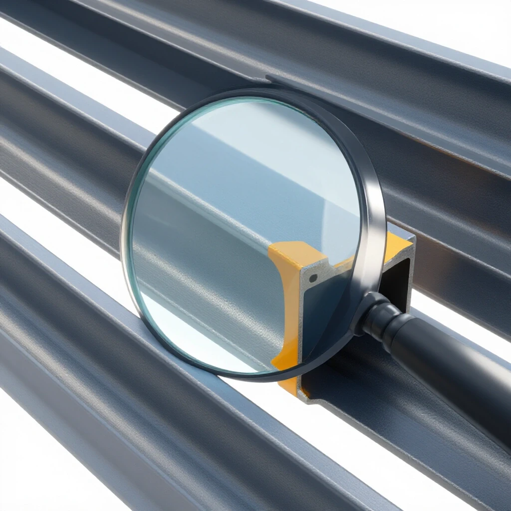
Visual verification is the process of looking for obvious physical flaws in the steel. This includes checking for rust, deep pits, or factory defects like laminations—where the steel layers didn’t bond correctly during the milling process.
I always start by wiping down the steel with a solvent. This reveals hidden cracks or “mill scale scabs” that might trap contaminants in the weld. I also look for “sweep” or “camber” in long beams. Steel is rarely perfectly straight from the mill. If a beam has a significant bow, I need to know that before I start tacking it to other components, as the heat of welding will only make the distortion worse.
- Surface Condition: Check for oil, grease, paint, or heavy rust.
- Material Integrity: Look for cracks, laminations, or deep gouges.
- Straightness: Use a string line or laser to check for bowing in long members.
Dimensional and Joint Fit-Up Assessment
Dimensional assessment involves using precision tools to ensure the steel has been cut to the correct length and that all angles are square. Fit-up assessment focuses on the gap between the pieces (root opening) and the alignment of the edges.
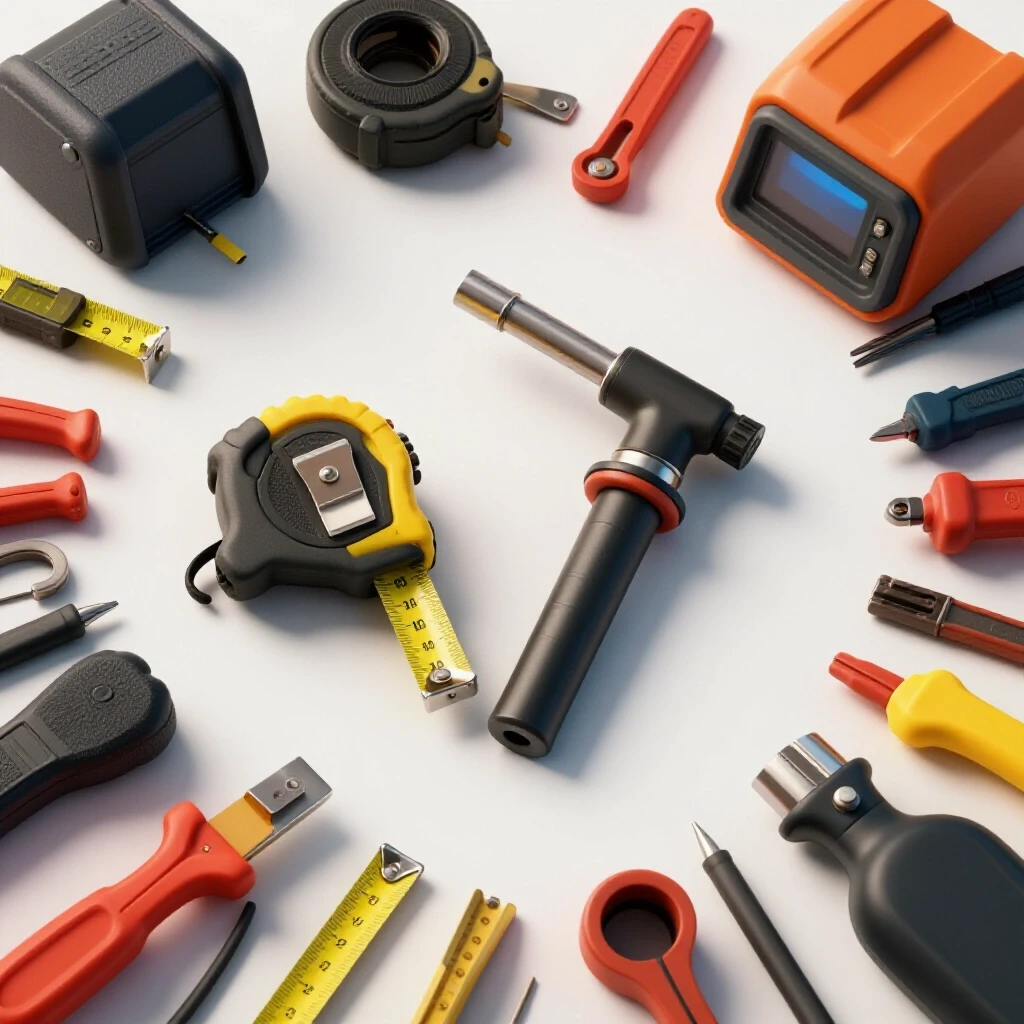
I use a set of dedicated “setup squares” and “gap gauges” for this. For structural joints, the root opening must be consistent. If the gap is too wide, you risk burn-through; if it’s too tight, you won’t get full penetration. I also verify the “fit-up” of the bevels. If I’m welding 1/2-inch plate, I want a 30-degree bevel on each side to create a 60-degree included angle. Checking this with a protractor takes ten seconds but ensures a sound weld.
- Length Verification: Measure twice with a calibrated tape or laser measure.
- Squareness Check: Use the 3-4-5 triangle method for large frames.
- Bevel Angle: Verify with a dedicated weld gauge or protractor.
- Root Opening: Ensure a consistent gap using a spacer or feeler gauge.
- Tack Strategy: Plan tack locations to minimize heat distortion.
Implementing Lean Tooling and Measurement Stations
Lean tooling is an organizational strategy that focuses on having exactly what you need, where you need it, without any excess. In a fabrication shop, this means creating dedicated stations for measuring and prepping steel.
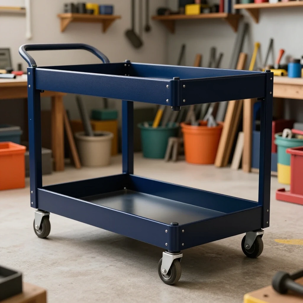
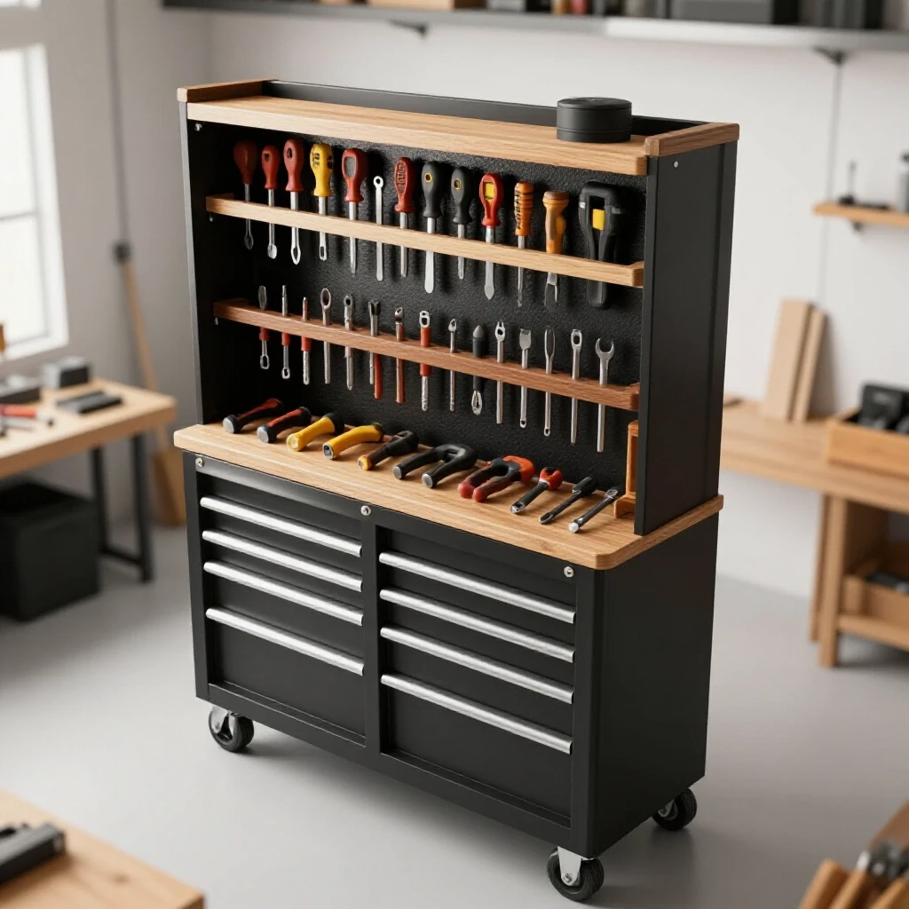
When I moved to a lean workflow, I stopped keeping my tools in a rolling chest. Instead, I built shadow boards at each station. Now, the calipers, squares, and gauges used for checking structural steel are mounted on the wall right next to the assembly table. If a tool is missing, I see the empty shadow immediately. This prevents the frustration of “lost” tools and keeps the momentum of the project moving forward.
Actionable Tracking Frameworks for Quality Control
A tracking framework is a simple way to document that your inspections have been completed. This can be as simple as a clipboard with a printed list or a digital tablet synced to the cloud.
I use a simple “Job Traveler” system. Every project has a sheet of paper that follows it through the shop. There are checkboxes for “Material Inspection,” “Cut Verification,” and “Fit-up Approval.” No one is allowed to strike an arc until the “Fit-up Approval” box is initialed. This creates accountability. It also provides a record if a part fails later, allowing us to look back and see if the initial preparation was performed correctly.
Workshop Layout Matrix for Scaling Operations
A layout matrix is a planning tool used to decide where machines should be placed based on their frequency of use and the size of the material they handle.
I used a matrix to realize that my cold saw and my CNC table should be close together because they both process raw material. By grouping these “primary processing” tools, I created a “prep zone” where all initial inspections happen. This zone is equipped with high-intensity LED lighting, which is crucial for seeing fine defects in the steel. If you can’t see the crack, you can’t fix it.
| Station | Primary Tools | Inspection Task | Lighting Requirement |
|---|---|---|---|
| Intake | Tape Measure, String Line | Straightness & Surface | Natural/High Bay |
| Prep/Cut | CNC, Saw, Grinders | Dimensions & Bevels | Task Lighting (500+ Lux) |
| Assembly | Squares, Gap Gauges | Fit-up & Alignment | Diffused LED |
Conclusion: Practical Steps for Shop Evolution
Transitioning your shop into a high-efficiency environment is a journey of a thousand small adjustments. It starts with a commitment to systematic preparation. By optimizing your layout for material flow, ensuring your 3-phase power is stable, and managing your air quality, you create a foundation where precision is possible.
My advice to any shop owner looking to scale is to start with the “Five-Step Rule.” Organize your measurement and inspection tools so they are always within reach. Then, look at your power and air systems—not as expenses, but as investments in your output quality. When your structural steel is verified and prepped correctly before the first weld, the rest of the job becomes significantly easier and much more profitable.
Frequently Asked Questions
How do I check for laminations in structural steel?
Laminations are internal separations in the steel that often appear as thin lines or cracks on the cut edge of a beam or plate. To find them, clean the cut edge with a flap disc and look for any linear discontinuities. If you suspect a lamination, you can use a dye penetrant test or simply tap the area with a hammer; a “dead” thud instead of a ring can indicate an internal void.
What is the ideal root opening for structural joints?
The ideal root opening depends on the thickness of the material and the welding process. For most structural steel between 1/4-inch and 1/2-inch thick, a root opening of 1/16-inch to 1/8-inch is common. This gap ensures that the weld metal can penetrate the full depth of the joint. Always verify the gap is consistent along the entire length of the weld.
Why is 3-phase power better for fabrication shops?
3-phase power provides more constant torque to motors, which means your grinders and saws won’t slow down under load. This leads to a more consistent surface finish. It is also more efficient, often resulting in lower electricity bills for high-output shops. Additionally, many professional-grade CNC machines and large welders are designed specifically to run on 3-phase power.
How does air quality affect my measurement accuracy?
Fine metallic dust from grinding can settle on the precision surfaces of calipers, micrometers, and squares. This grit can cause the tool to read incorrectly or even scratch the workpiece. Furthermore, poor air quality makes for a hazy environment where visual inspections for surface defects become much more difficult and less reliable.
What is the most common mistake in shop layout?
The most common mistake is failing to account for the “in-feed” and “out-feed” space required for long structural members. Owners often place a saw or a CNC table in a spot that looks good on paper but doesn’t allow for a 20-foot beam to be loaded or unloaded without hitting another machine or a wall. Always map out the full path of your longest material.
Can I run a CNC plasma table on a rotary phase converter?
Yes, you can, but you must be careful. CNC electronics are sensitive to voltage fluctuations. You should ensure your rotary phase converter is “CNC rated,” which means it has extra capacitors to balance the voltage more precisely. Always check the voltage on the manufactured leg to ensure it stays within the machine manufacturer’s specifications.
How do I know if my shop floor can handle a heavy CNC table?
Check the thickness of your concrete slab. A standard 4-inch slab is usually sufficient for most light-to-medium CNC plasma tables. However, if you are installing a heavy water table or large plate racks, you may need to cut and pour a reinforced “thickened slab” in that specific area to prevent the floor from sinking or cracking over time.
What tools are essential for a pre-weld inspection station?
At a minimum, you should have a calibrated tape measure, a high-quality machinist square, a set of gap gauges (or “feeler” gauges), a weld fillet gauge, and a protractor for checking bevel angles. A bright, handheld LED light is also essential for performing thorough visual inspections of the steel’s surface.
(This article was written by one of our staff writers, Edward Sinclair. Visit our Meet the Team page to learn more about the author and their expertise.)