How to Grind Out and Repair Defective Welding Beads (Guide)
When a critical weld bead fails to meet standards, the silence in the shop feels heavier than the machinery. I have spent 18 years in industrial fabrication mills and custom setups, and I have learned that a defect is rarely just a “bad day.” It is a data point. Whether you are dealing with a porous bead that looks like Swiss cheese or a crack that appeared during cooling, the path to a solution is not found in frustration. It is found in a methodical, step-by-step diagnostic process. I have seen fabricators lose hours chasing “electrical gremlins” when the issue was actually a simple shielding gas restriction or a subtle machine misalignment. My goal is to help you move past the guesswork and develop the systematic skills needed to identify why a failure happened and how to fix it permanently.
Establishing a Systematic Diagnostic Framework
A diagnostic framework is a structured method for isolating variables to find the root cause of a mechanical or metallurgical failure. Instead of changing five things at once, we change one, test it, and observe the result to ensure the repair is based on facts rather than luck.
When I am faced with a faulty joint, I start by isolating the three pillars of fabrication: the machine, the material, and the operator technique. I begin with a visual audit. If a weld shows excessive spatter, I do not immediately assume the welder is broken. I check the shielding gas flow rate, looking for a steady 25 to 35 CFH (cubic feet per hour). I then inspect the wire feed tension, ensuring it is not slipping or crushing the wire. By narrowing the field of possibilities, I can determine if I am dealing with a mechanical failure, such as spindle backlash of more than 0.002 inches, or a simple consumable issue.
Identifying Substandard Weld Deposits and Surface Imperfections
Identifying weld imperfections involves recognizing visual and structural deviations like porosity, undercut, or lack of fusion. Understanding these defects allows a fabricator to choose the correct removal method and prevent the same issue from recurring in the next pass.
In my experience, the most common “hard-to-find” issue is internal porosity. This occurs when gas is trapped in the cooling metal. I look for clusters of small holes on the surface, which often indicate a draft in the shop or a contaminated gas line. Another common issue is “lack of fusion,” where the weld metal fails to bond with the base material. This is often a sign of incorrect travel speed or insufficient heat. I use a 10x magnifying glass to inspect the “toe” of the weld—the point where the bead meets the plate—to ensure there is a smooth transition rather than a sharp notch or undercut.
- Porosity: Caused by gas entrapment; looks like tiny pits or bubbles.
- Undercut: A groove melted into the base metal next to the weld toe.
- Lack of Fusion: The weld metal sits on top of the base metal without “wetting” in.
- Inclusions: Bits of slag or tungsten trapped inside the weld deposit.
- Cracking: Linear separations caused by internal stress or rapid cooling.
Selecting Abrasives for Effective Metal Removal
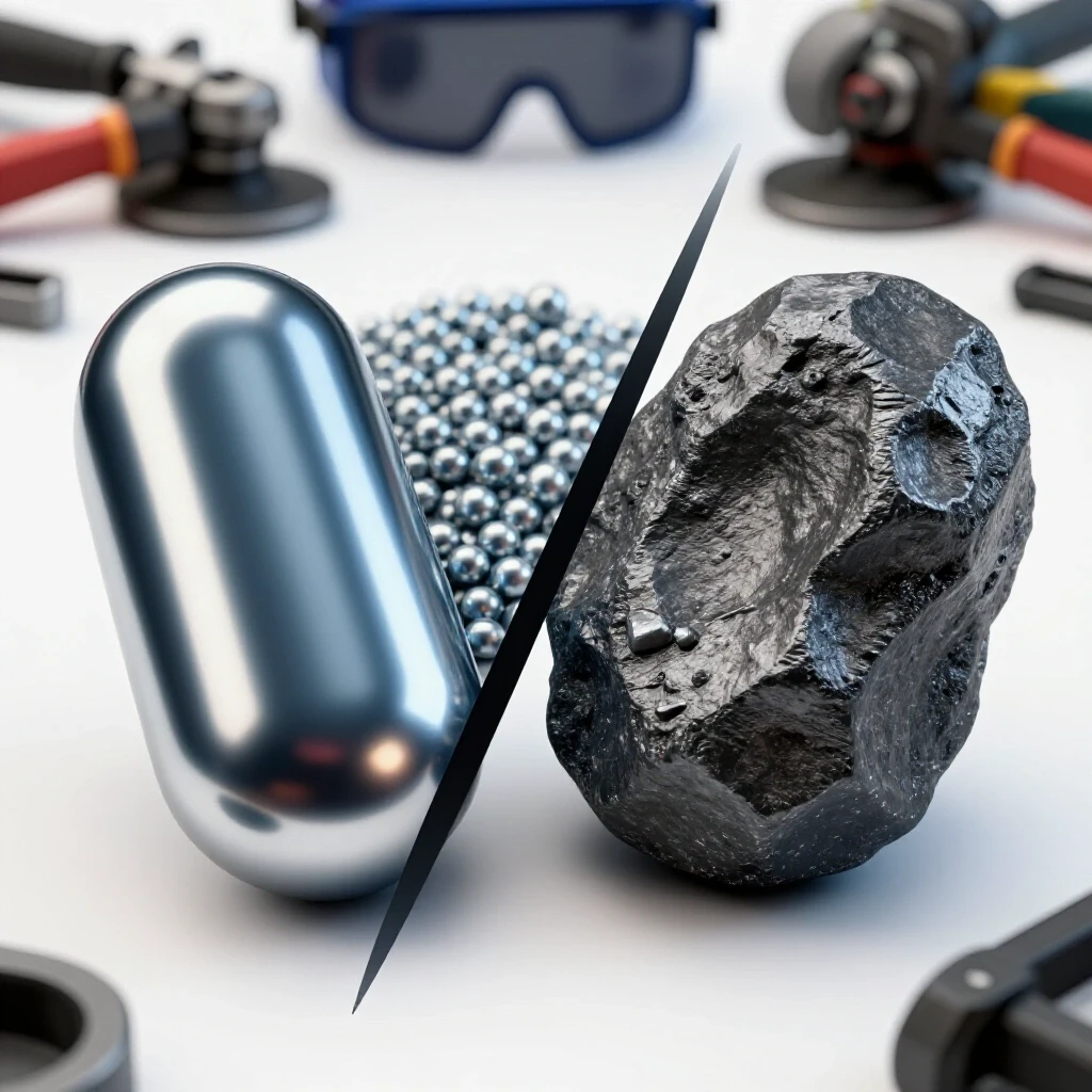
Selecting the right abrasive involves matching the wheel or disc type to the specific metal and the depth of the defect. Using the wrong grit can lead to overheating the base metal or “smearing” the defect, which hides the problem instead of removing it.
For heavy excavation of a failed bead, I reach for a 36-grit ceramic grinding wheel. These are aggressive and remove material quickly without generating excessive heat. If I am working on thinner material where I need to maintain structural integrity, I switch to a 60-grit flap disc. Flap discs provide a smoother finish and allow for more control, which is vital when you are trying to “feather” the edges of a repair area. I always check the RPM rating on the disc to ensure it matches my grinder’s output, typically around 10,000 to 12,000 RPM for a 4.5-inch tool.
Abrasive Selection and Application Table
| Abrasive Type | Grit Range | Primary Use | Benefit |
|---|---|---|---|
| Hard Grinding Wheel | 24 – 36 | Rapid removal of thick beads | High material removal rate |
| Flap Disc | 40 – 80 | Smoothing and blending | Cooler operation; less gouging |
| Resin Fiber Disc | 36 – 50 | Heavy-duty surface leveling | Aggressive but flexible |
| Carbide Burr | N/A | Tight corners and root passes | Precision excavation |
| Wire Wheel | N/A | Cleaning surface oxides | No base metal removal |
Strategic Excavation of Defective Material
Excavating defective material is the process of grinding out the “bad” metal until you reach sound, clean material. This step requires a steady hand and a “V-groove” approach to ensure the new weld has enough room to fuse properly with the base.
When I start grinding out a crack or a porous section, I do not just grind the surface. I “chase” the defect. If I see a pinhole, I grind until that hole is completely gone. I prefer to grind a “boat-shaped” groove that is wider at the top than the bottom. This allows the welding arc to reach the very bottom of the groove. If the groove is too narrow, the arc will jump to the sides, causing “bridging” and leaving a void at the bottom. I use a digital caliper to verify that I haven’t thinned the base metal by more than 10% of its original thickness unless a full-penetration repair is required.
Troubleshooting Root Causes of Weld Porosity
Troubleshooting weld porosity requires a systematic check of the gas delivery system, base metal cleanliness, and environmental factors. Porosity is rarely a single-source problem and often results from a combination of minor leaks and surface contaminants.
I once spent three days diagnosing a porosity issue on a custom aluminum frame. We checked the gas, changed the wire, and even swapped the machine. It turned out to be a tiny pinhole in the internal gas hose inside the welder’s drive roll cabinet. Every time the wire fed, it pulled a microscopic amount of air into the line. Now, I always perform a “static pressure test.” I turn on the gas, trigger the flow, then kink the hose at the torch and watch the regulator. If the pressure drops, I know I have a leak.
- Check Gas Flow: Ensure the regulator is set between 25-35 CFH.
- Inspect Nozzle: Look for “spatter buildup” that disrupts gas shields.
- Clean the Base: Use a dedicated stainless steel brush for aluminum or a flap disc for mill scale on steel.
- Verify Gas Quality: Check for moisture in the lines or a “bad bottle” of shielding gas.
- Monitor Drafts: Even a small fan or an open door can blow away your shielding gas.
Resolving Machine Misalignment and Tool Chatter
Machine misalignment and tool chatter are vibrational issues that occur when the equipment lacks rigidity or components are out of tolerance. These vibrations can cause wavy weld beads or premature tool failure in machining operations.
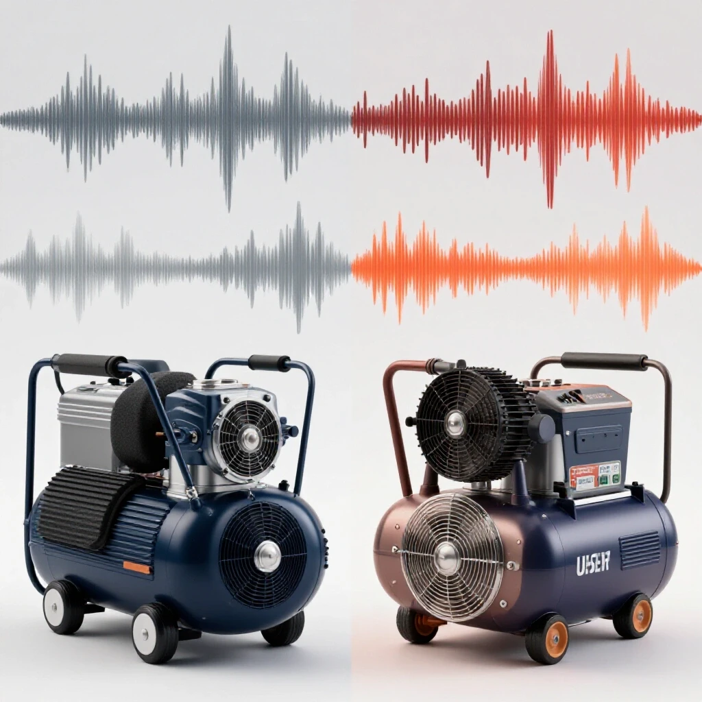
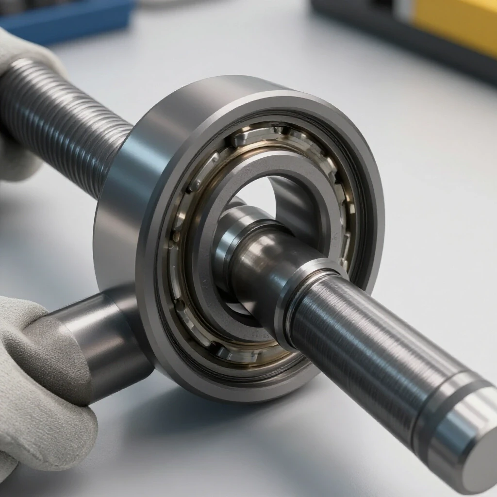
In my repair logs, I often note that “chatter” is a symptom of a harmonic imbalance. If you are grinding a repair and the tool starts to bounce, you are likely hitting a resonant frequency. I solve this by changing the tool speed or the pressure I apply. In a lathe or mill, chatter often comes from spindle backlash. I use a dial indicator to check for movement; if I see more than 0.002 inches of play, I know the bearings or the gibs need adjustment. A rigid setup is the only way to ensure a clean, repeatable repair.
Executing the Corrective Repair Pass
Executing a corrective repair pass involves re-welding the excavated area using refined techniques to ensure full penetration and a defect-free finish. This step is about applying the lessons learned from the initial failure to create a stronger joint.
Before I lay down the new bead, I “pre-heat” the area slightly with a torch if the metal is thicker than 1/4 inch. This slows the cooling rate and prevents “cold-start” defects. I start the arc about half an inch ahead of the excavation, move backward into the groove to establish the puddle, and then proceed forward. This “back-step” technique ensures the beginning of the repair is fully fused. I maintain a tight arc length—roughly the diameter of the wire—and watch the “puddle” closely to ensure it is wetting into the side walls of my ground-out groove.
Diagnostic Math and Mechanical Tolerances
Diagnostic math involves using specific measurements and formulas to calculate feed rates, heat input, and mechanical clearances. These numbers provide an objective baseline for determining if a machine or process is operating within its designed limits.
I rely heavily on “Feed-Per-Tooth” calculations when troubleshooting tool chatter. If a cutter is rubbing instead of cutting, it generates heat and vibration. I use the formula: Feed Rate = RPM x Number of Teeth x Feed-Per-Tooth. For example, if I am using a 2-flute end mill at 2,000 RPM with a desired 0.002 IPT (inches per tooth), my feed rate must be 8 inches per minute. If my machine cannot maintain this due to motor controller faults or lead screw wear, the repair will fail.
Mechanical Calibration Checklist
- Spindle Runout: Measure with a dial indicator; should be less than 0.0005 inches.
- Lead Screw Backlash: Check for “dead spots” in handwheel movement; target under 0.003 inches.
- Shielding Gas Flow: Verify at the torch nozzle using a portable flowmeter.
- Voltage Drop: Measure at the machine terminals while under load; should not exceed 3% to 5%.
- Ground Clamp Resistance: Check with an Ohmmeter; should be near 0 Ohms.
Case Study: Isolating Vibrational Damage in a Support Frame
I once worked on a large motor mount that kept cracking at the same weld joint every six months. The fabricators kept grinding it out and re-welding it, but the crack always returned. They thought it was a “bad weld,” but I suspected a structural alignment fault. I used a smartphone vibration spectrum analyzer app to look at the harmonics while the motor was running.
I discovered that the motor was running at 1,750 RPM, which perfectly matched the natural resonant frequency of the support arm. The weld wasn’t failing because it was weak; it was failing because it was being shaken apart by “resonant harmonics.” We didn’t just fix the weld; we added a gusset to change the stiffness of the arm, moving its resonant frequency away from the motor’s operating speed. This solved a two-year problem in one afternoon by looking at the “why” instead of just the “what.”
Maintaining a Repair Log and Maintenance History
A repair log is a detailed record of every failure, diagnostic step, and solution implemented in the shop. Keeping this history allows you to spot patterns over time and prevents you from solving the same problem twice.
I keep a simple notebook where I record the date, the machine, the symptoms, and the final fix. For example, if I notice that my MIG welder starts acting up every time the shop humidity hits 80%, I can correlate that to moisture in the liner. Without that log, I might spend hours checking the motor brushes or the circuit board. Documentation is the difference between a “parts changer” and a true diagnostic specialist.
- Date and Machine ID: Track which piece of equipment is failing.
- Symptom Description: Be specific (e.g., “erratic arc at 180 amps”).
- Variables Tested: List what you checked (e.g., “gas flow, ground clamp, wire tension”).
- Root Cause Found: What was the actual “smoking gun”?
- Correction Taken: How did you fix it permanently?
Mastering the Art of Systematic Troubleshooting
Mastering systematic troubleshooting is a journey of patience and observation. It requires moving away from the “just grind it and try again” mentality and moving toward a data-driven approach. When you encounter a defective bead or a vibrating tool, see it as a puzzle to be solved. Check your mechanical tolerances, verify your gas flow, and ensure your abrasives are suited for the task. By following these structured steps, you reduce downtime, save on wasted materials, and build a reputation as the person who can fix what others can’t. The next time a weld fails, don’t reach for the grinder first—reach for your diagnostic checklist.
Frequently Asked Questions
How deep should I grind when removing a weld crack?
You must grind until the crack is no longer visible, even under magnification. I recommend grinding an additional 1/8 inch past the visible end of the crack to ensure you have removed the “stress riser” that caused it. Always use a “V” or “U” shaped groove to allow for full penetration during the repair.
Why does my grinder leave “swirl marks” that show up in the new weld?
Swirl marks are often caused by using an abrasive that is too coarse or by holding the grinder at too steep an angle. If these marks are deep, they can trap slag or gas, leading to new defects. Switch to a 60 or 80-grit flap disc for the final pass to smooth the surface before re-welding.
Can I use a wire brush instead of grinding out porosity?
No. A wire brush only cleans the surface oxides. Porosity is a structural defect located inside the weld metal. You must mechanically remove the “bubbly” metal with a grinding wheel or carbide burr until you reach solid metal, then re-weld the area.
What is the best way to prevent undercut during a repair?
Undercut is usually caused by too much heat or an incorrect torch angle. When repairing a groove, pause slightly at the edges of the weld to allow the metal to fill in against the “walls” of the groove. Ensure your voltage is not set too high for your travel speed.
How do I know if my shielding gas is contaminated?
If you see “black soot” or extreme porosity despite having a high flow rate, your gas may be contaminated with moisture or air. Check all fittings with soapy water to find leaks. If the problem persists, try a different bottle of gas to rule out a “bad batch” from the supplier.
Is it necessary to pre-heat the metal before a repair weld?
For mild steel thinner than 1/4 inch, it is usually not necessary. However, for thicker sections or high-carbon steels, pre-heating to 200-400 degrees Fahrenheit helps prevent “hydrogen cracking” and ensures the repair fuses deeply into the base metal.
How can I tell the difference between a “cold start” and lack of fusion?
A “cold start” happens at the very beginning of the weld where the metal hasn’t reached temperature yet, resulting in a bead that sits on top of the plate. Lack of fusion can happen anywhere along the bead. Both require grinding out the area to create a groove that allows for better heat penetration.
What should I do if the metal “warps” during the repair?
Warping is caused by localized heat expansion. To minimize this, use “stitch welding” (short beads in different areas) rather than one long continuous pass. You can also use “heat sinks”—thick blocks of copper or aluminum clamped near the weld—to soak up excess heat.
Why do I keep getting “spatter” even after cleaning the metal?
Excessive spatter is often an electrical or settings issue. Check your “stick-out” (the distance between the tip and the work); it should be about 3/8 to 1/2 inch. Also, check your polarity; MIG welding steel should be DCEP (Direct Current Electrode Positive).
How often should I calibrate my welding machine’s wire feed speed?
I recommend a “bucket test” once a month if you are doing precision work. Trigger the wire for 10 seconds, measure the length, and multiply by six to get your actual Inches Per Minute (IPM). Compare this to the machine’s dial to ensure accuracy.
(This article was written by one of our staff writers, Paul Whitaker. Visit our Meet the Team page to learn more about the author and their expertise.)