How to Clean and Replace a Clogged MIG Gun Liner (DIY Fix)
In my eighteen years of troubleshooting industrial fabrication setups, I have learned that the most frustrating failures are rarely the loudest ones. It is not always a motor blowing or a structural beam snapping. Often, it is the subtle, intermittent stutter in a wire feed that ruins a critical pass. You are mid-weld, the rhythm is perfect, and suddenly the wire hesitates. The arc pops, the puddle becomes unstable, and you are left looking at a mess of porosity and cold lap.
Early in my career, I spent hours chasing “ghosts” in the drive motor of a heavy-duty feeder, convinced the electronics were failing. After dismantling the drive housing, I realized the motor was fine; it was simply fighting a massive amount of friction inside the torch lead. The internal conduit was packed with a decade’s worth of copper flaking and shop dust. That day taught me a vital lesson in metalworking diagnostics: always start with the physical path of the consumable.
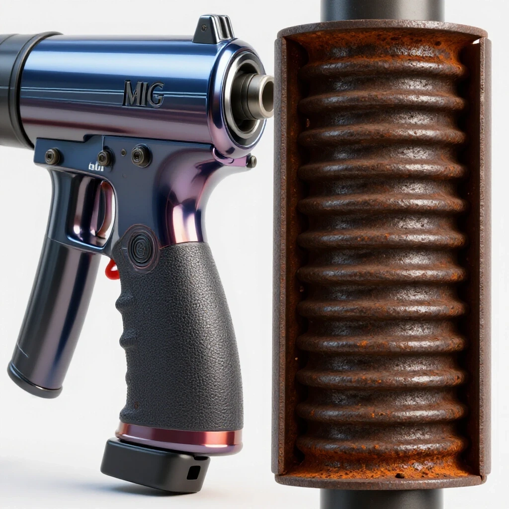
When wire delivery becomes erratic, many fabricators over-tighten their drive rolls. This is a mistake. It crushes the wire into an oval shape, which only increases friction further down the line. Instead, a systematic approach to inspecting and servicing the internal wire guide is the only way to ensure long-term reliability and weld quality.
Identifying the Signs of a Compromised Internal Conduit
Recognizing when the internal path of the welding wire is restricted is the first step in any diagnostic workflow. This involves observing stuttering wire delivery or “bird’s nesting” at the drive rolls, which suggests the wire is meeting resistance before it reaches the contact tip. When the wire cannot move freely, the feeder motor works harder, leading to heat buildup and mechanical strain.
In a professional shop, downtime is the enemy. If you notice the wire “chattering” as it exits the gun, or if the wire seems to slip despite high drive roll tension, the conduit is likely fouled. I categorize these symptoms into three stages: minor friction, intermittent blockage, and total obstruction.
- Minor Friction: You might notice the wire speed seems slightly inconsistent, or the arc sounds “crispy” rather than a smooth hum.
- Intermittent Blockage: The wire stops for a fraction of a second, then lurches forward. This often causes the wire to burn back to the contact tip.
- Total Obstruction: The drive rolls spin, but the wire stays stationary, eventually buckling at the feeder (the “bird’s nest”).
Wire Feed Failure Diagnostic Matrix
| Symptom | Probable Location | Diagnostic Test |
|---|---|---|
| Wire slips at rolls | Drive assembly | Check roll groove wear and tension settings. |
| Burn-back at tip | Contact tip or liner | Inspect tip for bore wear; check liner for kinks. |
| Erratic arc/chatter | Internal conduit | Perform the “pull test” with the gun straight. |
| Bird’s nesting | Entry point of liner | Verify liner is trimmed flush with the power pin. |
| Rapid tip wear | Misaligned liner | Check if the liner is centered in the diffuser. |
Preliminary Diagnostic Steps for Wire Feed Irregularities
Systematic testing is required to confirm that the resistance is located within the torch lead rather than the spool or drive mechanism. This phase focuses on isolating variables by manually checking wire movement through the disconnected gun assembly. By removing the influence of the feeder motor, you can feel the exact amount of drag the wire is experiencing.
I always start by straightening the gun lead completely. A coiled lead adds inherent friction. Once straight, I release the drive roll tension and attempt to pull the wire through the gun by hand at the nozzle end. If it requires more than a few pounds of force, the internal guide is compromised.
- Isolate the Spool: Ensure the spool brake is not too tight. It should only be tight enough to prevent the wire from unspooling when the motor stops.
- Inspect the Drive Rolls: Look for “shavings” or metal dust around the rolls. If you see a pile of silver or copper dust, your wire is being “shaved” because it is hitting an obstruction in the liner.
- Check the Inlet Guide: Ensure the small tube leading the wire into the gun’s power pin is aligned. A gap here of even 0.040 inches can cause the wire to snag.
The “Pull Test” Metric
For a standard 15-foot torch, a 0.035-inch steel wire should slide through a clean conduit with minimal resistance. If you feel “notches” or grinding sensations while pulling the wire manually, the internal surface of the guide is either scored or clogged with debris.
Mechanical Restoration of the Wire Pathway
The process of removing debris, such as metal shavings or dust, from the existing conduit can often resolve feed issues. Using pressurized air or specific cleaning agents can often restore smooth movement without necessitating a full component replacement. This is a vital maintenance skill that can extend the life of your consumables by months.
I have found that most clogs are a mixture of copper coating from the wire and shop particulates. Over time, these form a “sludge” inside the spiral of the liner. To clean it, you must first remove the wire from the torch entirely.
- Compressed Air Method: Use a blowgun with a rubber tip. Seal it against the power pin end of the gun and blast air at 30 to 50 PSI. You will often see a cloud of dust exit the nozzle end.
- Solvent Flushing: For stubborn clogs, a quick-drying electronic cleaner or brake cleaner can be sprayed into the liner. Warning: You must blow the liner completely dry with air afterward. Any residual solvent can contaminate your weld puddle and cause severe porosity.
- Mechanical Agitation: Sometimes, feeding a short length of wire in and out rapidly while the air is blowing helps break up compacted debris.
Building on this, if the air blast brings out large metal flakes, the liner is likely physically damaged. Internal “burrs” can develop if the wire has been allowed to kink. In these cases, cleaning is only a temporary fix, and a full replacement is the only way to prevent recurring tool chatter and weld defects.
Precision Installation of a New Internal Wire Guide
The step-by-step procedure for seating a fresh liner includes critical measurements for trimming and deburring. Proper seating ensures that the wire transitions smoothly from the drive rolls into the torch without snagging or buckling. This is where most intermediate fabricators fail; they treat the liner like a “drop-in” part, but it requires precise fitting.
When I replace a liner, I treat it like a machining operation. The tolerances matter. If the liner is too short, the wire will vibrate in the gap between the liner and the contact tip, leading to arc instability. If it is too long, it will bunch up and cause excessive drag.
Step-by-Step Replacement Workflow
- Removal: Lay the gun lead perfectly flat on the floor. Remove the nozzle, contact tip, and gas diffuser. Unscrew the liner nut at the power pin and pull the old liner out.
- Inspection of the Lead: Check the rubber jacket for any deep cuts or melted spots. A damaged jacket can allow the internal conduit to kink more easily.
- Feeding the New Liner: Slide the new liner into the power pin. Do this slowly. If you feel it snag, rotate the liner while pushing.
- Seating the Nut: Once the liner is fully inserted, tighten the liner nut at the power pin. Ensure the O-ring is seated to prevent gas leakage.
- The Critical Trim: At the torch end, the liner will be sticking out. You need to trim it so it seats perfectly inside the diffuser. For most standard torches, the liner should protrude roughly 1/2 inch to 3/4 inch from the torch neck before the diffuser is installed.
- Deburring: This is the most skipped step. After cutting the liner with side cutters, the end will be squashed. Use a small needle file or a dedicated deburring tool to open the hole back up. The wire must enter a perfectly round, smooth opening.
Linear Measurement and Tolerance Guide
| Component | Target Tolerance | Impact of Error |
|---|---|---|
| Liner Protrusion | +0.0625″ / -0″ | Too short causes “micro-arcing” inside the gun. |
| Deburred Bore | 100% Round | Squashed ends cause wire shaving and clogs. |
| Power Pin Gap | < 0.030″ | Large gaps lead to bird’s nesting at the rolls. |
| Lead Curvature | > 24″ Radius | Tight coils increase friction by 400%. |
Troubleshooting Persistent Friction After Replacement
Sometimes, even after a fresh installation, the wire feed remains erratic. This is where we must look at the interface between the feeder and the gun. Interestingly, many “liner issues” are actually alignment issues at the power pin.
I once worked on a shop’s main fabrication table where they replaced the liner three times in a week. The issue wasn’t the liner; it was a misaligned drive roll housing. The wire was hitting the edge of the liner at a 10-degree angle, causing it to shave metal immediately upon entry. We used a laser alignment tool—a simple laser pointer taped to a straight wire—to find that the feeder was sitting 1/8 inch lower than the gun inlet.
- Check the Inlet Guide Tube: This small tube sits between the drive rolls and the gun. If it is worn or “grooved,” it will create friction before the wire even reaches the liner.
- Verify Wire Diameter: Ensure the liner is sized for the wire. A 0.045-inch liner is great for 0.045-inch wire, but using it for 0.030-inch wire allows the wire to “snake” inside the conduit, creating inconsistent feed speeds.
- Monitor Heat: If the torch neck is getting excessively hot, the liner may be expanding and gripping the wire. This is common in high-amperage applications where the cooling system (or gas flow) is insufficient.
Advanced Maintenance: The Role of Wire Lubrication and Cleaning Pads
To prevent future clogs, many professionals use treated pads that clip onto the wire before it enters the drive rolls. These pads serve two purposes: they wipe off shop dust and apply a microscopic layer of non-conductive lubricant.
In my experience, these are essential in shops that do a lot of grinding. The airborne metallic dust is magnetic and will find its way onto your welding wire. Once that dust gets pulled into the liner, it acts like sandpaper.
- Install a “Wiper” Pad: Place it just before the drive rolls.
- Inspect the Pad Weekly: If it turns black within a day, your shop’s air quality is affecting your equipment’s reliability.
- Avoid Over-Lubrication: Too much lubricant can attract more dust, creating a “lapping compound” that wears out your contact tips prematurely.
Case Study: The 15-Foot Lead and the “Ghost” Porosity
I was called to a shipyard to diagnose a series of failed X-ray welds. The welders were complaining about intermittent porosity that only appeared in the middle of long seams. After checking the gas flow at the regulator (which was fine), I decided to look at the wire delivery.
We found that as the welders moved, they often coiled their 15-foot leads. This increased the friction in the aged liners just enough that the wire speed would drop by 5 to 10 percent for a few seconds. This drop in wire speed changed the arc length and the heat input, leading to a loss of puddle control and atmospheric contamination.
We replaced all the liners with high-quality, polished steel versions and implemented a “no-coil” rule for the leads. The porosity issues disappeared. This case highlighted that the internal conduit is not just a tube; it is a critical component of the welding “circuit” that dictates the consistency of the metallurgy.
Summary of Mechanical Standards for Wire Conduits
Maintaining a clear path for the welding wire is a fundamental skill for any serious fabricator. It requires a move away from “guessing” and toward “measuring.” By following a systematic cleaning and replacement protocol, you eliminate one of the most common variables in weld failure.
- Clean the liner every time you finish a 33-lb or 44-lb spool of wire.
- Replace the liner immediately if you experience a severe bird’s nest or if the wire shows signs of physical “shaving.”
- Always deburr the cut end of a new liner to a tolerance of 0.005 inches to ensure a smooth transition.
- Maintain a straight lead whenever possible to minimize the coefficient of friction.
By mastering these small mechanical details, you ensure that your equipment works with you, rather than against you. The result is less downtime, fewer wasted consumables, and significantly higher weld quality.
Frequently Asked Questions
How often should I realistically blow out my torch lead?
I recommend blowing out the internal conduit with compressed air every time you change a spool of wire. In high-dust environments, such as shops where heavy grinding occurs near the welding stations, doing this halfway through a spool can prevent the accumulation of “sludge” that leads to feed stuttering.
Can I reuse a liner if I’ve had a bird’s nest?
It depends on where the buckle occurred. If the wire buckled at the drive rolls and didn’t kink the liner itself, you can usually clear the wire and continue. However, if the wire jammed inside the liner and you had to pull it out with force, the internal coils of the liner are likely stretched or deformed. In that case, replacement is the only reliable fix.
What is the best tool for trimming a new wire guide?
High-quality side cutters or “lineman’s” pliers are standard, but they often crush the spiral. I prefer using a thin dremel cutoff wheel for a square, clean cut. Regardless of the tool, you must follow up with a needle file to ensure the internal diameter is perfectly round and free of sharp edges.
Why does my wire keep “shaving” at the entrance of the power pin?
This is almost always an alignment issue. Check the gap between the drive roll exit guide and the liner entrance. If the liner isn’t seated deeply enough into the power pin, the wire has room to wander and strike the sharp edge of the liner. Ensure the liner is flush and the inlet guide is centered.
Does the material of the liner matter (e.g., steel vs. Teflon)?
Yes, absolutely. Steel liners are the standard for steel and stainless steel wires. However, if you are running aluminum wire, you must use a Teflon or graphite liner. Aluminum is soft and will “gall” or rub off inside a steel liner, causing a total clog within minutes.
How do I know if the friction is in the liner or the contact tip?
Perform the “pull test” with the contact tip removed. If the wire pulls easily without the tip but binds when the tip is installed, the problem is the tip. If it binds even without the tip, the obstruction is in the internal conduit.
Can a clogged liner cause porosity in my welds?
Indirectly, yes. While the liner doesn’t carry gas, a clog causes erratic wire feed. When the wire speed fluctuates, the arc length changes. This can cause the arc to become too long, which breaks the shielding gas envelope and allows nitrogen and oxygen to contaminate the weld, resulting in porosity.
What happens if I trim the liner too short?
If the liner is too short, it leaves a gap inside the gas diffuser. The welding wire will “whip” or vibrate in this gap. This leads to excessive wear on the diffuser and the contact tip, and it can cause the wire to snag, leading to intermittent feeding.
Is it okay to use WD-40 to lubricate a sticky liner?
No. Never use standard lubricants like WD-40 or oil inside a torch lead. These substances will contaminate the weld puddle, causing porosity and structural defects. If you must use a lubricant, use only those specifically designed for welding wire, and use them sparingly.
Why is my wire guide turning blue or black at the end?
Discoloration is a sign of extreme heat. This usually means your contact tip is failing and the arc is “transferring” further back into the gun, or your gas flow is too low to cool the front-end consumables. Check your gas flow rate and ensure your contact tip is the correct size for the wire.
How do I measure the “drag” on my wire accurately?
While most pros do it by “feel,” you can use a small fish scale. Attach it to the wire at the nozzle and pull. A clean, straight 15-foot lead should show less than 3-5 lbs of resistance. If it spikes above 10 lbs, your conduit needs immediate service.
Can I use a larger diameter liner for smaller wire?
You can, but it isn’t ideal. For example, running 0.030-inch wire through a 0.045-inch liner allows the wire to “wave” inside the tube. This increases the total distance the wire travels and can lead to a “spongy” feed feel, making it harder to maintain a consistent arc.
(This article was written by one of our staff writers, Paul Whitaker. Visit our Meet the Team page to learn more about the author and their expertise.)