How to Evaluate Metalworking Tool Quality Before Buy (Tips)
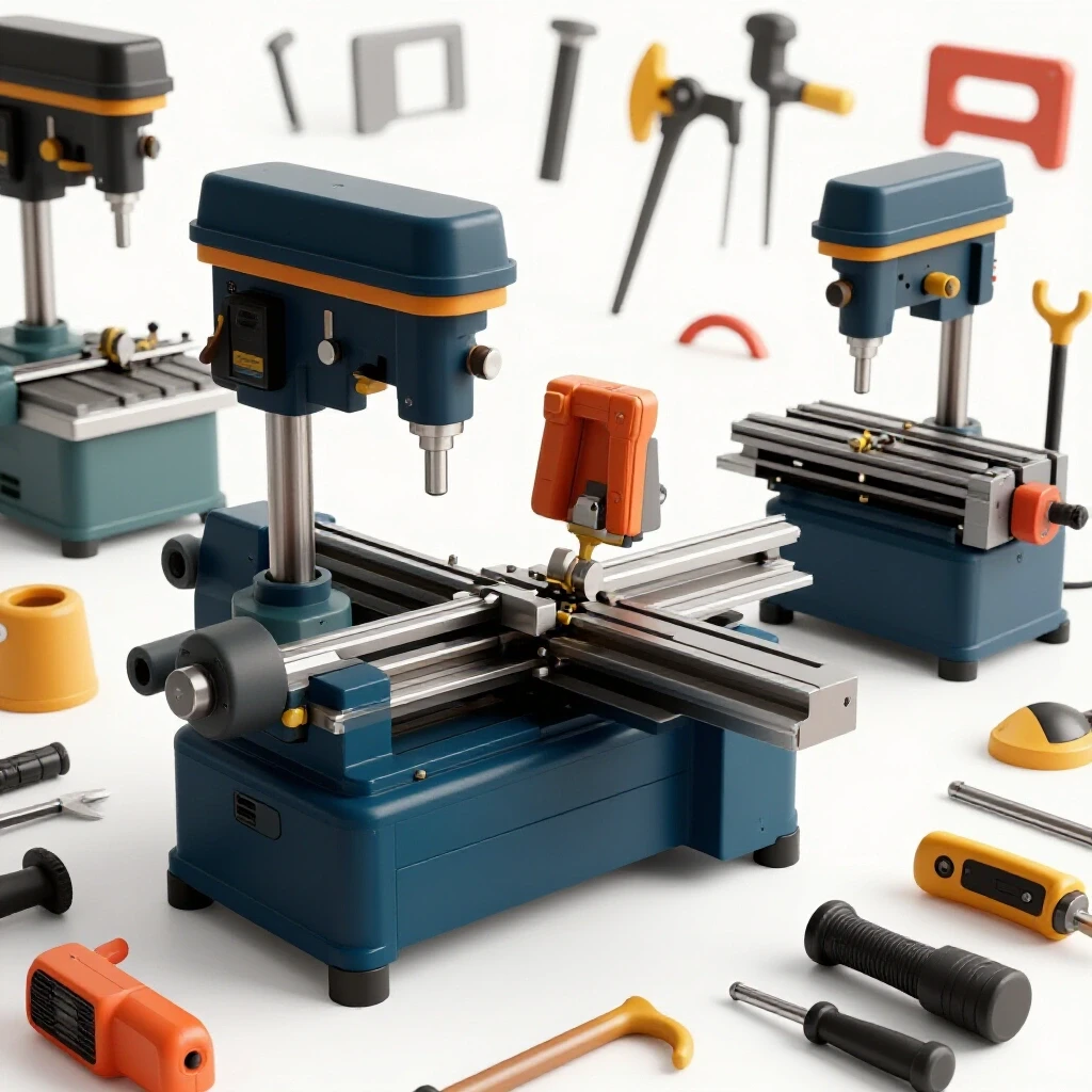
I have spent 17 years in industrial maintenance, often elbow-deep in the guts of machinery that failed long before its time. In my shop, I have seen how a shiny coat of powder-grade paint can mask porous castings and undersized bearings. When you are preparing to invest in a new lathe, mill, or drill press, the marketing materials often focus on horsepower and digital features while ignoring the structural integrity that actually determines the life of the tool.
Choosing workshop machinery is a process of looking past the surface to see how the equipment was truly engineered. I remember a specific instance where a colleague bought a milling machine based on its impressive electronic speed control. Within six months, the thin sheet-metal stand began to flex, causing the spindle to vibrate so violently that it ruined every finish. We eventually tore it down and found that the internal gears were made of a soft alloy rather than hardened steel. That experience reinforced my belief that physical inspection is the only way to verify what you are actually getting.
In this guide, I will share the methods I use to inspect mechanical components and structural designs. We will look at how to measure spindle runout, evaluate the quality of cast iron, and understand the differences in motor architecture. By the end of this article, you will have a framework for assessing any piece of metalworking equipment with the eye of a maintenance specialist.
Analyzing Structural Rigidity and Casting Quality
The foundation of any precision metalworking tool is its frame, which is usually made of cast iron. This material is chosen for its ability to absorb vibrations, a property known as dampening, which prevents the tool from chattering during a cut. High-quality castings are seasoned to relieve internal stresses, ensuring the machine stays straight over years of use.
Heavy castings are the backbone of accuracy because they provide the mass necessary to resist the cutting forces generated by the tool bit. When I evaluate a machine, I look for the thickness of the ribs inside the base and the overall weight-to-size ratio. A machine that feels light for its footprint is often using thinner walls, which leads to “harmonic resonance”—that annoying high-pitched squeal that ruins surface finishes.
The Role of Material Density in Vibration Dampening
Density in machine tools refers to the mass per unit of volume in the frame, which directly affects how the machine handles mechanical energy. Grey cast iron is the industry standard because the graphite flakes within the metal act as tiny shock absorbers. This prevents energy from traveling through the tool and into your workpiece.
Interestingly, not all cast iron is created equal. I often look for “Meehanite” or similar high-grade classifications, which indicate a controlled casting process. If you can see the internal structure of a machine, look for a smooth, consistent texture. Large pits or a “sandy” appearance usually suggest a cheap casting process that might contain air pockets, compromising the structural integrity of the entire unit.
Evaluating Bedway Hardness and Finish
The bedways are the precision-ground surfaces that the carriage or table slides upon. These must be incredibly hard to resist wear from the constant friction of moving parts. Many quality machines use “flame-hardened” or “induction-hardened” ways, which create a tough outer layer while keeping the core of the casting ductile.
When inspecting these surfaces, I look for the “grind pattern.” A high-quality finish will have a consistent, cross-hatched or mirrored appearance without deep scratches or gouges. If you see “scraping” marks—small, decorative-looking crescents—these are often hand-applied to create tiny oil pockets that keep the slides lubricated. However, be wary of “power scraping” that looks too uniform, as it is sometimes used to hide poor machining.
| Material Type | Vibration Dampening | Structural Stiffness | Common Application |
|---|---|---|---|
| Grey Cast Iron | Excellent | High | Lathe beds, mill columns |
| Ductile Iron | Moderate | Very High | High-stress gears, spindles |
| Fabricated Steel | Poor | Moderate | Low-cost stands, enclosures |
| Aluminum Alloy | Very Poor | Low | Hobby-grade tool components |
Assessing Motor Design and Power Delivery
The motor is the heart of the machine, but its rated horsepower is often a misleading metric. In my experience, a 2-HP motor on a budget machine often performs worse than a 1-HP motor on an industrial unit because of how the power is delivered. You need to look at the motor type, the cooling system, and the drive mechanism.
Building on this, the way a motor handles heat is a primary indicator of its long-term reliability. I prefer motors with large, aluminum cooling fins and a dedicated fan. If a motor is totally enclosed without any visible cooling, it may rely on a lower duty cycle, meaning it will overheat if you push it through a long day of heavy hogging cuts.
Comparing Brushed and Brushless Motor Systems
Brushed motors use physical carbon brushes to transfer electricity to the spinning rotor, while brushless motors use electronic controllers to manage the magnetic fields. Brushless systems are generally superior for metalworking because they offer constant torque even at low speeds. This is critical when you are drilling large holes or threading at slow RPMs.
In my teardowns, I’ve found that brushless motors also run much cooler and have fewer parts that wear out over time. However, the electronics that drive them must be high-quality. I check for the size of the heat sinks on the motor controller; if the electronics are crammed into a tiny, unvented box, they are a likely failure point.
Drive Belts versus Geared Heads
The drive system transfers power from the motor to the spindle. Geared heads provide a positive, non-slip connection that is excellent for high-torque applications, but they can be noisy and expensive to repair if a tooth breaks. Belt drives, particularly those using multi-groove V-belts, offer a smoother, quieter operation and act as a “mechanical fuse” that slips if the tool crashes.
As a result, many modern precision lathes have moved toward belt drives combined with variable frequency drives (VFDs). This setup gives you the torque of a geared head with the vibration-free finish of a belt. When evaluating a belt system, check the width of the belts and the material of the pulleys—cast iron or steel pulleys are far superior to plastic or thin aluminum ones.
Measuring Spindle Precision and Bearing Quality
The spindle is the component that holds the chuck or the tool, and its accuracy is measured in “runout.” Runout is the amount of wobble the spindle has as it rotates. If a spindle has high runout, your holes will be oversized, and your parts will never be truly round.
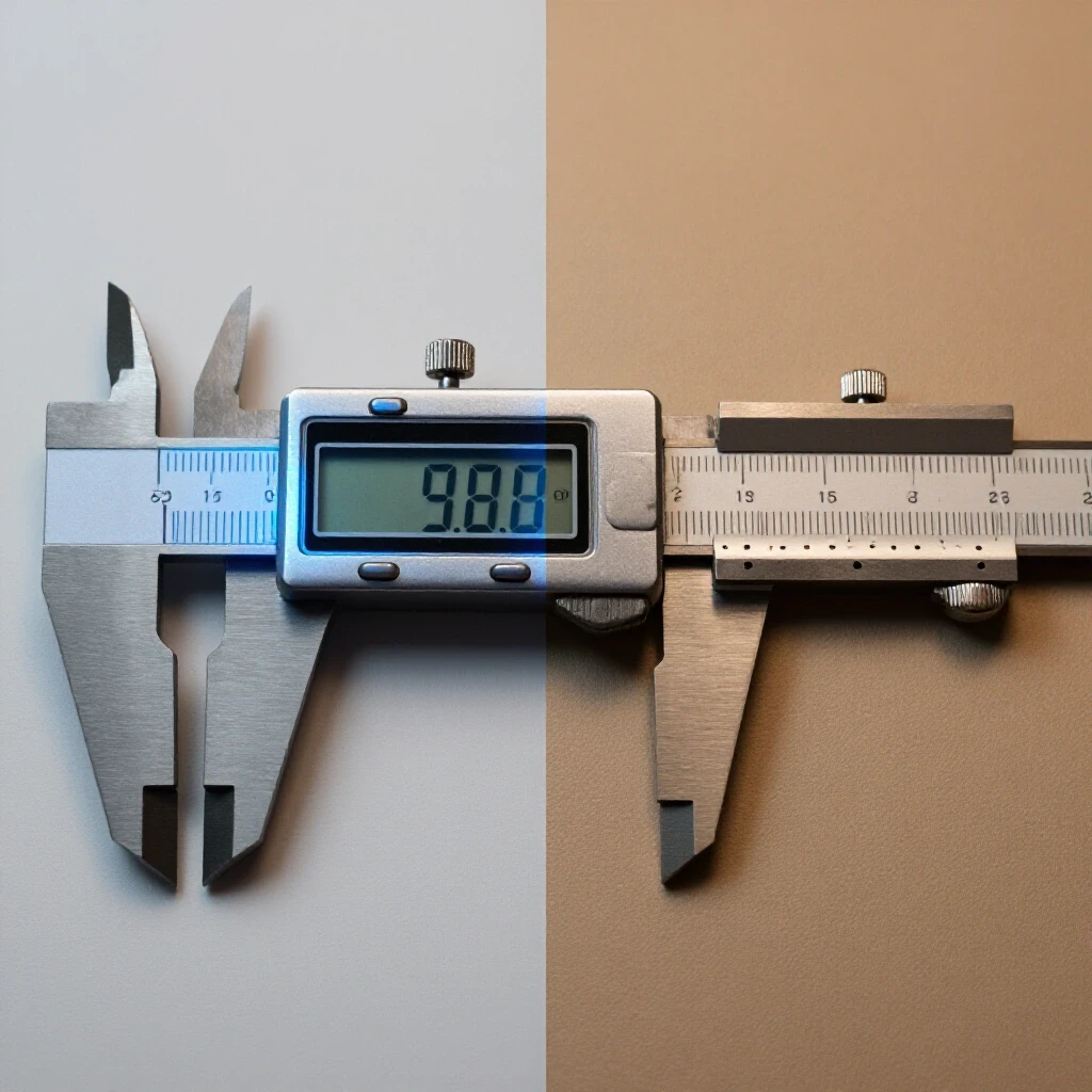
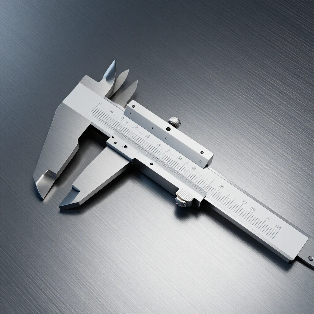
To verify this, I use a dial test indicator with a resolution of 0.0005 inches. I place the indicator tip against the inside taper of the spindle and rotate it by hand. On a high-quality machine, the needle should barely move. If you see more than 0.001 inches of movement, the machine will struggle with precision work.
Understanding Bearing Types and Preload
Spindle bearings carry the load of the cutting forces while allowing the spindle to spin freely. Most high-end metalworking tools use tapered roller bearings or angular contact ball bearings. These are designed to handle both “radial” loads (pushing sideways) and “axial” loads (pushing along the length of the spindle).
“Preload” is the process of tightening the bearings against each other to remove any internal play. I check for this by trying to move the spindle up and down with a pry bar while watching my dial indicator. If there is any “clunk” or measurable movement, the bearings are either poorly adjusted or undersized for the machine’s capacity.
- Tapered Roller Bearings: Best for high-torque, low-speed work like heavy turning.
- Angular Contact Bearings: Best for high-speed precision, common in milling spindles.
- Deep Groove Ball Bearings: Often found in cheaper tools; they lack the rigidity for serious metalworking.
Spindle Taper and Tool Retention
The internal taper of the spindle (such as Morse Taper or R8) must be ground with extreme precision. I always inspect the inside of the taper with a bright light to look for “scoring” or uneven marks. A poor taper fit will cause the tool holder to vibrate, which leads to “fretting”—a type of wear that eventually ruins both the spindle and your tools.
Interestingly, the method of tool retention also matters. On a mill, the drawbar should be made of hardened steel with clean threads. If the drawbar feels “mushy” when you tighten it, the threads may be stretching, which is a sign of low-grade hardware that will eventually fail under the stress of heavy milling.
Inspecting Slide Fitment and Mechanical Tolerances
The slides, or “ways,” allow the different parts of the machine to move relative to each other. The fitment here must be tight enough to prevent “gib slap” (wiggle) but loose enough to move smoothly. This balance is achieved through the use of “gibs,” which are tapered strips of metal that can be adjusted to take up wear.
I evaluate the slides by moving the table to the extreme ends of its travel. On a poorly made machine, the table will feel tight in the middle and loose at the ends. This happens because the manufacturer didn’t grind the ways perfectly flat. A high-quality machine will have a consistent “feel” across the entire range of motion.
Evaluating Lead Screw Backlash
Backlash is the “dead space” you feel when you change the direction of a handwheel. It is caused by the gap between the threads of the lead screw and the nut it rides in. While some backlash is normal (usually 0.003 to 0.005 inches), excessive backlash makes it very difficult to hit precise dimensions.
In my workshop, I prefer machines with adjustable nuts that allow you to “dial out” the backlash as the machine wears. I also look at the lead screws themselves. They should be “rolled” or “ground” threads, not “cut” threads. Ground threads are much smoother and provide more accurate movement, which you can feel as a lack of grittiness when turning the handwheels.
The Importance of Torsional Stiffness in Tool Posts
On a lathe, the tool post holds the cutting bit. If this component isn’t rigid, the bit will deflect under the pressure of the cut, leading to “chatter.” I check for torsional stiffness by mounting a long bar in the tool post and applying pressure by hand. If I can see the tool post flexing or pivoting on its base, the machine will struggle with stainless steel or other hard alloys.
Building on this, the “compound slide” is often a weak point. I look for a wide base and heavy-duty locking bolts. Some budget machines use a single center bolt, which is prone to vibrating loose. A professional-grade machine will often use a circular T-slot or multiple heavy bolts to secure the tool post assembly.
Analyzing Electrical Components and Control Boards
Modern metalworking tools rely heavily on electronics, especially for variable speed control and digital readouts (DROs). However, the electrical cabinet is often where manufacturers cut corners. I always open the access panels to look at the wiring and the circuit board layout.
A well-engineered machine will have organized wiring with “ferrules” (metal sleeves) on the ends of the wires to prevent fraying. If the cabinet looks like a “rat’s nest” of loose wires and hot-glue, it is a sign of poor quality control. These loose connections are the leading cause of intermittent electrical failures that are a nightmare to diagnose.
Inspecting Switchgear and Emergency Stops
The switches you touch every day should feel robust. I prefer industrial-grade “clunk” switches over cheap plastic buttons. The emergency stop (E-stop) is particularly important; it should be a large, mushroom-headed button that cuts power instantly.
I also check the “contactor”—the large relay that actually turns the motor on and off. If the contactor is undersized, the internal points will eventually weld themselves shut, which is a significant safety hazard. A quality machine will use a contactor rated for at least 1.5 times the motor’s full-load amperage.
Digital Readouts and Sensor Integration
Digital Readouts (DROs) are now common even on mid-range machines. These use “glass scales” or “magnetic scales” to track the position of the slides. When inspecting a machine with a DRO, I look at how the scales are mounted. They should be protected by sturdy aluminum covers to keep out metal chips and coolant.
If the scales are exposed, they will eventually get contaminated and lose their accuracy. I also check the cables; they should be “armored” with a metal coil to prevent them from being cut by sharp chips. A machine that integrates the DRO into the frame casting is usually a sign of a more thoughtful, higher-quality design.
| Component | Inspection Point | What to Look For |
|---|---|---|
| Circuit Board | Capacitors and Heat Sinks | Large, well-spaced components with cooling |
| Wiring | Wire Termination | Ferrules and labeled wires in tidy looms |
| Switches | Actuation Feel | Positive “click” and industrial-grade housing |
| Encoders | Mounting Brackets | Rigid, protected mounting with chip guards |
Testing Speed Controllers and Torque Delivery
The speed controller regulates how much power the motor receives. On many budget machines, the motor loses almost all its torque at low speeds. This makes it impossible to use large drill bits or perform heavy threading operations. I test this by running the machine at its lowest speed and attempting to (safely) put a small load on the spindle.
A high-quality controller will use “back-EMF” or “encoder feedback” to sense when the motor is slowing down under load. It will then automatically pump more current into the motor to maintain the RPM. This is often called “constant torque” or “vector control.” If the machine simply stalls as soon as the tool touches the metal, the controller is a basic, low-quality unit.
Evaluating Variable Frequency Drives (VFD)
For machines with AC motors, a VFD is the gold standard for speed control. A VFD takes standard wall power and converts it into a three-phase signal that can be precisely tuned. When I inspect a machine with a VFD, I look for the brand and the cooling fan on the drive itself.
A good VFD will have a programmable display that allows you to adjust “ramp-up” and “ramp-down” times. This prevents the machine from jerking when you start it, which protects the gears and the motor. If the VFD is hidden and has no user interface, it is likely a “stripped-down” version that offers fewer protections for the motor.
Practical Steps for a Pre-Purchase Inspection
If you have the opportunity to see a machine in person, you should bring a few basic tools: a dial test indicator, a flashlight, and a set of feeler gauges. These allow you to perform a “teardown-style” inspection without actually taking the machine apart.
- Check for “Play”: Grab the table or carriage and try to shake it. You shouldn’t feel any movement. If you do, use your feeler gauges to see if there is a gap between the slides.
- Listen to the Bearings: Run the machine at its highest speed. It should hum, not growl. A “growling” sound usually indicates pitted bearings or poorly meshed gears.
- Test the Heat: After running the machine for 10 minutes, feel the motor and the spindle housing. They should be warm, but not too hot to touch. Excessive heat in the spindle housing indicates the bearings are too tight or lack lubrication.
- Inspect the Oil: Look at the sight glasses. The oil should be clear, not milky. Milky oil means water or coolant has contaminated the lubrication system, which can cause internal rust.
Verifying Parts Availability and Manual Quality
A machine is only as good as the parts you can get for it. I always ask to see the manual. A high-quality tool will come with a detailed “exploded view” diagram and a parts list with specific part numbers. If the manual is just a few pages of poorly translated text, you will have a hard time finding replacement bearings or gears five years down the road.
Building on this, I look for “standardized” parts. Does the machine use standard-sized bearings (like 6205 or 30209)? Does it use standard V-belts? If the machine uses proprietary parts that you can only get from the manufacturer, you are at their mercy if they ever go out of business or stop supporting that model.
Summary of Mechanical Benchmarks
When you are making a final decision, it helps to have a set of hard numbers to compare. These benchmarks are based on my years of maintaining industrial equipment and represent a “good” standard for a serious workshop tool.
- Spindle Runout (TIR): Should be less than 0.001 inches (0.025mm) for general work, and 0.0005 inches (0.012mm) for high-precision tasks.
- Weight-to-Power Ratio: For a lathe, look for at least 150 lbs of cast iron for every 1 HP of motor power. This ensures the frame can handle the torque.
- Lead Screw Backlash: New machines should have less than 0.005 inches of play in the handwheels.
- Bedway Hardness: Look for a rating of at least 40-50 HRC (Rockwell Hardness Scale) on the ways.
By focusing on these physical realities rather than the branding on the side of the machine, you can confidently select a tool that will provide decades of accurate service. Remember, the best machine isn’t always the one with the most features; it’s the one with the best iron and the tightest tolerances.
Frequently Asked Questions
What is the most important factor when choosing a metalworking lathe? The structural rigidity of the bed and the precision of the spindle bearings are the two most critical factors. A lathe with a flexible bed will never produce straight parts, and a spindle with high runout will never produce round parts. Focus on the weight of the casting and the measured runout before looking at speed ranges or digital features.
How can I tell if a machine uses high-quality cast iron? Look for the “dampening” test. If you strike the side of the casting with a rubber mallet, it should produce a dull “thud.” If it rings like a bell, the iron is likely thin or of a lower grade that won’t absorb vibrations well. Also, look for a “Meehanite” certification, which is a high standard for casting quality.
Why is “runout” so important in a milling machine? In a mill, runout causes the cutting tool to wobble. This means only one or two teeth of a multi-flute end mill are actually doing the work, which leads to rapid tool wear, poor surface finish, and inaccurate dimensions. A spindle with 0.002 inches of runout can effectively double the chip load on a single tooth of the cutter.
Are brushless motors always better than brushed motors? Generally, yes. Brushless motors provide better torque at low speeds and generate less heat. However, they rely on complex electronic controllers. A high-quality brushed motor with a robust speed controller can still be a very reliable choice for many workshop applications, especially if you prefer simpler electronics that are easier to repair.
What should I look for in a machine’s electrical cabinet? Look for organization and protection. Wires should be tucked into looms, and terminals should be clearly labeled. A large, well-ventilated cabinet with industrial-grade contactors and heat sinks on the motor drives indicates a machine built for long-term use rather than a budget hobby tool.
How much backlash is acceptable in a new machine? On a new machine with manual lead screws, anything between 0.002 and 0.005 inches is considered excellent. If the backlash is more than 0.010 inches out of the box, it suggests poor machining of the nuts or lead screws, which will make precision work frustrating.
What is the difference between “ground” and “scraped” ways? Ground ways are finished on a large precision grinding machine to be perfectly flat and smooth. Scraping is a manual or semi-manual process of removing tiny amounts of metal to create high spots and oil-retaining low spots. While hand-scraping was once the gold standard, modern precision grinding is often just as accurate and more consistent.
Why does the weight of the machine matter so much? Weight equals mass, and mass equals vibration resistance. In metalworking, the cutting process creates significant forces that want to push the tool and the workpiece apart. A heavier machine can resist these forces without flexing, allowing for deeper cuts and better accuracy.
How do I check if the spindle bearings are worn or low-quality? Run the machine at high speed and listen for any grinding or growling noises. Then, use a dial indicator to check for radial play by prying on the spindle. Finally, check the temperature after 15 minutes of use; the housing should be warm (around 100-120°F) but never painfully hot.
Is a belt drive better than a geared head? It depends on your needs. Belt drives are quieter and produce a better surface finish because they don’t transmit gear vibrations to the spindle. Geared heads are better for very heavy, low-speed work where you need maximum torque. For most modern workshops, a belt drive with a Variable Frequency Drive (VFD) offers the best of both worlds.
(This article was written by one of our staff writers, Steven Brooks. Visit our Meet the Team page to learn more about the author and their expertise.)