How to Identify and Avoid Tolerance Stack-Up Errors (Guide)
Scaling a workshop from a hobby space into a professional fabrication environment is rarely about buying a single piece of equipment. It is a fundamental shift in how you think about space, power, and the way parts interact with one another. I have spent more than 20 years navigating this transition. In that time, I have learned that the biggest threats to productivity are not usually the big, obvious mistakes. Instead, they are the small, hidden errors that grow larger as a project moves through the shop.
When I first integrated a CNC plasma system, I thought my biggest challenge would be the software. I was wrong. The real hurdle was realizing that my manual layout habits did not translate to automated production. In a manual setup, you can “fudge” a fit or file down a high spot. In a high-output environment, those tiny variations add up. If three parts are each off by just a hair, the final assembly might not fit at all. This guide focuses on how to build a shop infrastructure that identifies these compounding errors before they ruin a production run.

The Hidden Impact of Compounded Dimensional Variations
Compounded dimensional variations occur when the small sizing errors of individual parts add up across an entire assembly. This often results in components that do not align, requiring expensive rework or causing total project failure during the final stages of fabrication.
In my experience, the transition to high-volume work reveals every flaw in your measurement process. If you are building a single gate, a sixteenth of an inch might not matter. If you are cutting fifty precision brackets on a CNC plasma table, that same sixteenth can become a disaster. You must understand how these errors accumulate. This is often called “stacking,” where the plus or minus limits of every cut, bend, and weld combine.
I remember a project involving a modular racking system. Each vertical support was slightly out of square, and each horizontal beam was a fraction too long. Individually, the parts looked fine. Once we tried to bolt the tenth section together, the entire structure was leaning four inches off-center. We had to scrap three days of work. To avoid this, you need to calculate the worst-case scenario for your tolerances before the first spark flies.
Calculating Total Error Using Arithmetic and Statistical Methods
Arithmetic stacking assumes every part is off by the maximum allowed amount in the same direction. Statistical methods, like Root-Sum-Square, recognize that it is unlikely every part will be perfectly “wrong” at the same time, providing a more realistic estimate of fit.
For most micro-manufacturers, simple arithmetic is the safest starting point. You simply add the maximum possible error of every component in a sequence. If you have five parts and each has a variance of 0.010 inches, your total possible error is 0.050 inches. If your assembly cannot handle a 0.050-inch gap or overlap, you must tighten your individual part requirements.
- Arithmetic Method: Sum of all individual tolerances (Max Error = T1 + T2 + … + Tn).
- Root-Sum-Square (RSS): The square root of the sum of the squares of the tolerances. This is better for high-volume runs where errors tend to cancel each other out.
- Worst-Case Design: Planning the assembly so it functions even if every part hits its maximum or minimum size limit.
Optimizing Advanced Workshop Layouts for Linear Material Flow
An advanced workshop layout organizes machinery and workstations in a logical sequence to minimize the physical distance materials travel. This reduces the time spent moving heavy sheets and prevents the physical bottlenecks that slow down high-output fabrication.
When I reorganized my shop five years ago, I used a stopwatch to track how far a sheet of steel traveled. It was eye-opening. I was moving material in a “star” pattern, constantly crossing my own path. This created a massive bottleneck at the main aisle. By moving to a linear flow, I reduced material handling time by 30%. In a professional shop, every foot of travel is a cost.
You should aim for a “dock-to-stock” or “raw-to-ready” flow. Raw material enters one end of the shop, moves to the CNC plasma table, then to the deburring station, then to welding, and finally to finishing. This prevents the back-and-forth foot traffic that kills throughput. I recommend keeping a 3-foot minimum access zone around every machine to allow for maintenance and safe movement.
Workshop Layout Flow Comparison
| Layout Type | Material Travel Path | Efficiency Level | Best Use Case |
|---|---|---|---|
| Random/Evolutionary | Scattered/Criss-cross | Low | Small hobby repairs |
| U-Shaped Flow | Entry and Exit near each other | Medium | Narrow shops with one door |
| Linear Flow | Straight line through stations | High | High-volume production |
| Cellular Layout | Grouped by part family | Very High | Specialized component manufacturing |
Integrating 3-Phase Power Systems for Industrial Machinery
A 3-phase power converter allows a standard residential or light commercial single-phase electrical service to run heavy-duty industrial motors. This provides the stable voltage and high torque required for large compressors, CNC systems, and milling machines.
Most home-based fabricators eventually hit a wall with 240V single-phase power. When I added a commercial-grade air compressor to support my CNC plasma table, my lights dimmed every time it kicked on. That is a sign of an overtaxed system. To scale up, you need 3-phase power. Since utility companies often charge a fortune to drop a 3-phase line to a residential area, most of us use converters.
I prefer Rotary Phase Converters (RPC) for their durability. An RPC uses a single-phase motor to spin a three-phase idler motor, generating the third leg of power. It is a “dumb” but reliable technology. For more sensitive electronics, a Digital Phase Converter is better because it provides perfectly balanced voltage across all three legs. If your voltage is unbalanced by more than 5%, you risk overheating your expensive CNC motors.
Comparison of 3-Phase Power Solutions
- Static Converters: These are the cheapest but only provide 3-phase power for starting. The motor runs at about 2/3 power afterward. I do not recommend these for CNC work.
- Rotary Phase Converters (RPC): These are the workhorses. They can power multiple machines at once. They are loud, so I built an insulated enclosure for mine.
- Digital Phase Converters: These use solid-state electronics to create clean power. They are quiet and highly efficient but cost significantly more than rotary units.
- Variable Frequency Drives (VFD): Excellent for single machines like a lathe or mill. They allow for speed control but generally only power one motor at a time.
Designing High-Volume Dust and Fume Management Systems
High-volume air filtration involves using powerful blowers and specialized ducting to capture airborne particulates and fumes at the source. This protects the health of the operator and prevents fine dust from interfering with sensitive CNC electronics.
Air quality is often an afterthought until you spend eight hours cutting slats on a plasma table. The fine dust produced by thermal cutting is invasive. It gets into your lungs and your computer fans. I designed my first extraction system using a simple wall fan, but it was nowhere near enough. For a professional setup, you need to calculate your Cubic Feet per Minute (CFM) requirements based on the size of your cutting area.
Duct design is just as important as the fan itself. You want to avoid sharp 90-degree elbows, which create “static pressure loss.” Think of it like water flowing through a pipe; every bend slows it down. I use 45-degree wyes and large-diameter smooth-walled pipe to keep the air velocity high. According to industrial standards, you generally need about 1,000 to 2,000 CFM for a standard 4×8 plasma table to effectively clear the smoke.
Air Filtration Metrics and Maintenance
- CFM (Cubic Feet per Minute): The volume of air moved. Aim for 100-150 FPM (Feet per Minute) of “face velocity” at the opening of your hood.
- Static Pressure: The resistance the fan must overcome. Keep duct runs short to minimize this.
- Filter MERV Rating: Use MERV 13 or higher for fine metal dust.
- Maintenance Interval: I blow out my pre-filters every 20 hours of cutting and replace main filters every 6 months.
Calibrating CNC Gantry Systems to Prevent Motion Errors
Calibrating a CNC gantry involves aligning the mechanical rails and tuning the motor settings to ensure the machine moves exactly as the software commands. This process eliminates “backlash” and “slop” that lead to dimensional inaccuracies in finished parts.
When you transition to automation, the machine is only as accurate as its calibration. I once struggled with parts that were consistently 1/32 of an inch too small. I checked my CAD files, my kerf offsets, and my consumables. The problem ended up being a loose drive belt on the Y-axis. This is a classic example of a mechanical error creating a compounding variance.
You must decide between stepper motors and servo motors. Steppers are affordable and common in most entry-level CNC plasma table setups. However, they operate in an “open loop,” meaning if the torch hits a piece of tip-up slag and skips a step, the computer has no idea. Servos use “closed-loop” feedback encoders to constantly report their position. If a servo gets bumped, it knows it is off-track and will try to correct itself or shut down the machine.
Steps for System Commissioning and Calibration
- Square the Gantry: Use the 3-4-5 triangle method or a large precision square to ensure the X and Y axes are perfectly perpendicular.
- Check for Backlash: Move the axis in one direction, stop, and move it back 0.001 inches. If the machine doesn’t move, you have mechanical play that needs to be tightened.
- Calibrate Steps Per Inch: Command the machine to move exactly 12 inches. Measure the actual travel with a calibrated rule. Adjust the motor pulses in your software until the movement is exact.
- Test Repeatability: Run a program that moves the head around the table and returns to zero. If it doesn’t land in the exact same spot, check for slipping pulleys or loose couplings.
Managing Tooling Files and Software Workflow Optimization
Software workflow optimization involves creating a standardized process for moving designs from CAD to CAM to the machine controller. This ensures that kerf widths, lead-ins, and cut speeds are applied consistently to maintain part accuracy.
The “broken link” in many shops is the handoff between the design software and the machine. I use a standardized checklist for every new part. This prevents me from forgetting to account for the “kerf,” which is the width of the material removed by the plasma arc. If your kerf is 0.060 inches and you don’t account for it, every hole will be too large and every outer dimension will be too small.
I also recommend using “tool libraries” in your CAM software. Instead of guessing the settings for 10-gauge mild steel every time, I have a verified profile that includes the exact cut speed, pierce height, and voltage. This consistency is the only way to avoid the slow drift in quality that happens when you rely on memory.
Actionable Workflow Checklist
- Step 1: Geometry Check. Ensure all lines are joined and there are no overlapping vectors in your CAD file.
- Step 2: Kerf Compensation. Verify the “inside” or “outside” offset is applied correctly for the specific nozzle size.
- Step 3: Lead-in/Lead-out. Place these on the waste side of the cut to avoid “divots” on the finished edge.
- Step 4: Dry Run. Run the program with the torch off to ensure the gantry doesn’t hit any clamps or table limits.
Real-World Case Study: Reclaiming Floor Space and Accuracy
A few years ago, I helped a local fabricator who was struggling to scale. He had a 2,000-square-foot shop but could only produce about ten assemblies a week. His floor was cluttered with off-cuts, and his CNC table was buried under “work in progress.” We spent a weekend applying lean manufacturing principles.
First, we mapped his material flow. We moved his raw steel rack right next to the shop’s roll-up door. Then, we placed the CNC plasma table six feet away. We cleared a “dead zone” around the table for pallet jacks. By simply moving the deburring station to the other side of the table, we eliminated a 40-foot walk that his employees were making fifty times a day.
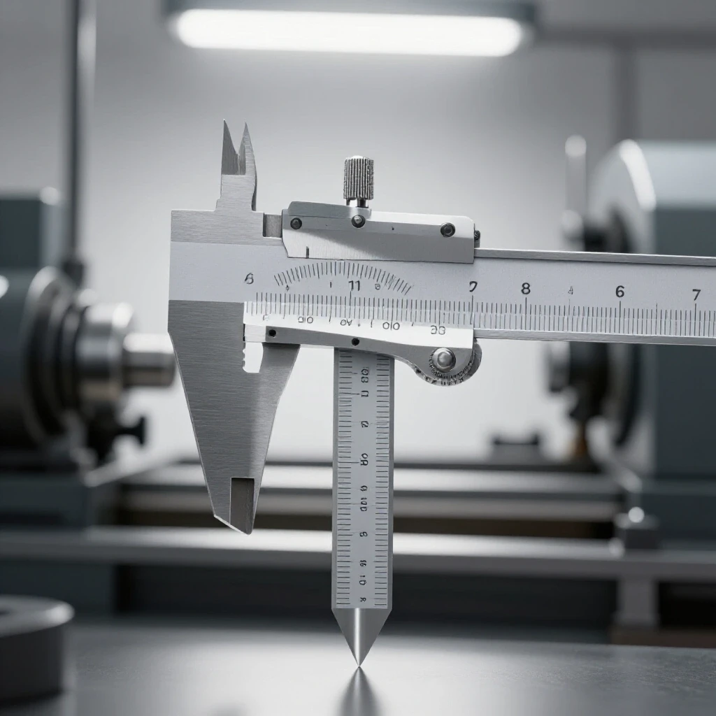
Second, we addressed his dimensional errors. He was experiencing a 15% scrap rate because parts wouldn’t fit during welding. We found that his slats were bent, causing the material to sit unevenly. By leveling the table and implementing a “first-article inspection” (checking the first part of every run with calipers), we dropped his scrap rate to less than 2%.
Machine Amortization and Capital Planning
| Equipment | Estimated Cost | Lifespan (Years) | Monthly Amortization |
|---|---|---|---|
| CNC Plasma Table (Entry Pro) | $15,000 | 7 | $178 |
| Rotary Phase Converter | $2,500 | 15 | $14 |
| Industrial Dust Collector | $4,000 | 10 | $33 |
| Welding Cell Upgrade | $6,000 | 8 | $62 |
Practical Next Steps for Scaling Your Shop
Transitioning to a semi-professional operation is a marathon, not a sprint. Do not try to change everything in one weekend. Start by measuring your current performance. Track your scrap rate and your “spindle time”—the actual hours your machines are cutting versus sitting idle.
Your first priority should be the shop layout. It costs nothing but time to move machines, and it yields the most immediate return on efficiency. Once your flow is linear, look at your power and air infrastructure. These are the foundations that allow automation to work reliably. Finally, obsess over your measurements. Use the arithmetic stacking method on your next complex project. If you can identify where the errors are coming from, you can stop them before they reach the welding table.
Frequently Asked Questions
What is the most common cause of parts not fitting in an assembly? The most common cause is failing to account for the thickness of the cutting tool (kerf) combined with minor bending errors. When these two small variations happen on multiple parts, the total error exceeds the allowable gap for a clean fit.
How do I know if I need a rotary phase converter or a digital one? If you are running simple motors like a drill press or a basic compressor, a rotary converter is fine. If you are running a CNC controller or a modern welder with sensitive circuit boards, a digital converter is safer because it provides cleaner, more balanced power.
How much space should I leave between my CNC table and the wall? I recommend at least 36 inches. You need enough room to walk around the machine for maintenance, to clear out dross, and to ensure your cable tracks have enough room to move without binding.
What is “static pressure” in a dust collection system? Static pressure is the resistance the air faces as it moves through your pipes. Long runs, small pipes, and sharp turns increase resistance. If your static pressure is too high, your fan won’t be able to pull enough air to clear the fumes effectively.
Why are my CNC parts coming out slightly oval instead of round? This is usually caused by “backlash” or “lost motion” in one of your axes. It means there is a tiny bit of play in the gears, belts, or lead screws. When the machine changes direction, that play results in a flat spot or an oval shape.
Is it better to use a water table or a downdraft table for plasma cutting? Water tables are cheaper and better at capturing heavy dust, but they can be messy. Downdraft tables are better for fine smoke and keep the parts dry, but they require a much more powerful (and expensive) fan and ducting system.
How often should I calibrate my CNC machine? I check my machine’s squareness once a month and do a full “steps per inch” calibration every time I tension the drive belts. If you notice your parts aren’t fitting like they used to, calibration should be your first check.
What is the best way to track material flow in a small shop? Use a piece of chalk or tape to mark the path of a single part from the time it enters as raw steel until it leaves as a finished product. If the lines look like a bowl of spaghetti, your layout needs work.
Can I run a 3-phase CNC machine on a VFD? Yes, but a VFD is typically designed to run one motor at a time. If your CNC machine has multiple motors (X, Y, and Z axes) plus a controller, a VFD might not work. In that case, a phase converter is the better choice.
How do I calculate the “worst-case” fit for my project? Add up the maximum possible size of every part in a row. Then, add up the minimum possible size of the space those parts must fit into. If the parts are bigger than the space in this scenario, you have a “stack-up” problem that needs to be fixed.
(This article was written by one of our staff writers, Edward Sinclair. Visit our Meet the Team page to learn more about the author and their expertise.)