How to Identify Critical Wear Signs on Cutting Tools (Tips)
I have spent the last 14 years standing on oily concrete floors, staring at steel through a welding hood, and measuring tolerances with a precision that borders on the obsessive. In my time as a mechanical engineer and shop floor fabricator, I have learned that a project’s success is rarely determined by the final weld alone. Instead, it is the result of every small action that came before it. One of the most overlooked factors in structural failure is the condition of the tools used to prep the metal. If your drill bits, end mills, or lathe inserts are failing, the heat and stress they transfer into your workpiece can create invisible flaws that haunt your build later.
In a professional setting, we treat tool degradation as a data point, not a nuisance. When I was inspecting heavy frame components for industrial trailers, I saw firsthand how a dull cutting edge could lead to micro-cracks in the heat-affected zone (HAZ) of a structural joint. This happens because a worn tool stops cutting and starts “plowing,” generating immense friction and heat. That heat changes the metallurgy of your steel, often making it brittle before you even strike an arc. For the risk-averse fabricator, understanding how to spot these early warning signs is a vital part of your workshop safety checklist.
Recognizing Flank Wear and Surface Erosion
Flank wear is the most common form of tool degradation, occurring on the side of the cutting edge that rubs against the workpiece. It appears as a flat, shiny “land” or scar that grows wider as the tool is used. Monitoring the width of this wear land is essential for maintaining dimensional accuracy and preventing sudden tool breakage during high-stress operations.
When you look at a cutting edge under a bright light, you might see a thin, bright line running along the flank. This is the wear land. In industrial standards, once this land reaches a width of 0.015 to 0.030 inches, the tool is considered functionally exhausted. Why does this matter to you in a garage fabrication safety context? As that land grows, the tool requires more force to push through the metal. This increased pressure can cause your workpiece to shift in its fixture or, worse, cause a drill bit to catch and spin the entire piece of metal, leading to a serious workshop injury.
- Visual Check: Look for a “shiny” strip parallel to the cutting edge.
- Measurement: Use a magnifying loupe with a scale to check the width.
- Physical Feedback: You will notice the tool requires more downward pressure to maintain the same cut rate.
- Safety Margin: If you are working on structural metal with a high yield strength, like 4140 steel, replace the tool sooner to avoid work-hardening the material.
Detecting Crater Formation on the Rake Face
Crater wear is a concave depression that forms on the top surface of the tool, known as the rake face, where the metal chips slide away. This is caused by a chemical and thermal reaction between the chip and the tool material at extremely high temperatures. If this crater grows too deep, it weakens the cutting edge until the tip eventually snaps off under load.
I remember a specific case where a fabricator was drilling 1/2-inch holes into a structural beam. He didn’t notice the deep cratering on his high-speed steel (HSS) bit. Mid-cut, the weakened edge collapsed. The sudden loss of cutting ability caused the drill motor to kick back, spraining his wrist and leaving a jagged, oversized hole that ruined the beam’s structural metal load capacity. To prevent this, you must inspect the “top” of your cutting edges. A visible dip or “scooped out” look means the tool’s structural integrity is compromised.
| Wear Indicator | Visual Appearance | Cause | Structural Risk |
|---|---|---|---|
| Flank Wear | Shiny flat land on the side | Abrasive rubbing | Dimensional inaccuracy, high heat |
| Crater Wear | Hollowed out top surface | High temp chip friction | Sudden tip breakage |
| Chipping | Jagged, notched edge | Thermal shock, vibration | Stress risers in workpiece |
| Built-Up Edge | Lumpy material on tip | Pressure welding | Surface tearing, poor fit-up |
Identifying Micro-Chipping and Edge Fractures
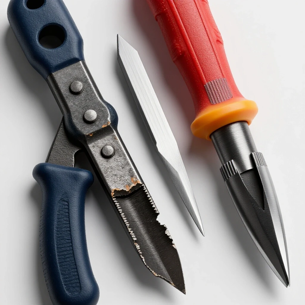
Micro-chipping involves small, irregular bits of the cutting edge breaking away, often due to excessive vibration or thermal shock. Unlike the smooth erosion of flank wear, chipping creates a serrated edge that acts like a saw rather than a knife. This produces a rough surface finish and can introduce small notches into your metal, which act as stress concentration points.
In structural design, a “stress riser” is a location where stress is concentrated, making it the most likely place for a crack to start. If your cutting tool is chipping, it is essentially carving thousands of tiny stress risers into your part. If that part is later subjected to a heavy load, those micro-notches can lead to a brittle fracture. I always tell my team: if the edge looks like a mountain range under a magnifying glass, it is no longer a precision tool; it is a liability.
- Vibration Check: If you hear a high-pitched “chatter” or screaming sound, the tool is likely chipping.
- Surface Finish: Run a fingernail (with the machine off!) across the cut surface; if it feels like a file, your tool edge is notched.
- Material Factor: Harder materials like stainless steel are more prone to causing chipping due to their work-hardening nature.
Monitoring Built-Up Edge (BUE) and Material Adhesion
Built-up edge, or BUE, occurs when small particles of the workpiece material weld themselves to the cutting tip under high pressure and heat. It might look like the tool is simply “dirty,” but this adhesion actually changes the geometry of the tool. This leads to a larger “effective” cutting radius, which increases the forces required to make the cut.
Interestingly, BUE is often transient; it builds up and then breaks off, frequently taking a piece of the tool material with it. This cycle causes rapid deterioration of the tool’s surface. When you see “lumps” of aluminum or steel stuck to your drill bit or end mill, stop immediately. If you continue, the tool will tear the metal rather than shear it, leading to poor joint preparation. Poorly prepared joints are a primary cause of welding defect troubleshooting issues, such as lack of fusion or trapped inclusions.
- Check for “Galling”: Look for silver or grey smears on the tool tip that don’t wipe away easily.
- Inspect the Chip: If the metal chips are coming off blue or purple (in steel), you have too much heat, which encourages BUE.
- Dimensional Drift: If your holes are consistently coming out 0.005 inches too large, BUE is likely the culprit.
Indirect Performance Indicators: Noise and Heat
Sometimes you don’t need a microscope to tell that a tool is failing; you just need to use your senses. A healthy cutting tool should produce a consistent, rhythmic sound and chips that are uniform in shape. When a tool begins to fail, the physics of the cut change. The friction increases, and the energy that should be going into shearing the metal is instead converted into heat and sound.
I’ve learned to listen for the “growl.” A dull tool doesn’t “hiss” through the metal; it growls. This noise is the sound of the tool rubbing against the material. Simultaneously, watch the heat. If you see smoke from your cutting fluid or the metal starts changing color (straw to blue), you are likely exceeding the heat-affected zone weakness threshold. This excessive heat can ruin the temper of your workpiece, making a structural joint unpredictable under load.
- Acoustic Clues: Listen for “chatter” (vibration) or “screaming” (high friction).
- Thermal Clues: Use an infrared thermometer; if the tool tip exceeds 400°F for HSS, it is losing its hardness.
- Chip Inspection: Look for “birds’ nests” or long, stringy chips that indicate the tool is no longer breaking the material correctly.
The Impact of Tool Health on Structural Joint Integrity
Why am I so focused on tool wear in a guide for risk-averse fabricators? Because the quality of your cut determines the quality of your weld. If you use a worn-out hole saw to prep a tube for a chassis, the fit-up will be sloppy. In the world of structural metal, a gap of even 1/16 of an inch can significantly weaken a weld joint because the weld metal has to “bridge” a larger area, increasing the risk of internal weld defects like porosity or cold-lapping.
Furthermore, a dull tool creates a smeared surface layer on the metal. This layer can trap oils, oxides, and dirt that a wire brush won’t reach. When you weld over this “smeared” surface, those contaminants are vaporized and trapped in the weld pool, causing porosity. By ensuring your tools are sharp and within wear limits, you are performing the first step of a comprehensive welding defect troubleshooting protocol.
Workshop Safety Checklist for Tool Inspection
To maintain a high standard of garage fabrication safety, I recommend a formal inspection routine. Don’t wait for a tool to break to replace it. Instead, treat tool inspection as a mandatory step in your project workflow.
- Pre-Project Inspection: Before starting a critical cut, inspect the tool under a 10x magnification loupe.
- Light Source Setup: Use a dedicated LED work light to spot the “glint” of a worn flank or a chipped edge.
- Tactile Test: Use a brass rod to gently feel the edge; a sharp tool will “grab” the brass, while a dull one will slide.
- Compare to New: Keep a “master” new tool in your drawer to visually compare against the one currently in your machine.
- Record Keeping: Note how many inches or holes a tool has cut. Most manufacturers provide an “expected life” metric based on material type.
Using Non-Destructive Testing (NDT) Logic in the Shop
In the industrial world, we use NDT to find hidden flaws. You can apply a simplified version of this logic to your cutting tools. For example, a “dye penetrant” test isn’t just for welds; it can be used on large, expensive milling cutters to find micro-cracks before they lead to a catastrophic failure. If you are working on a project with a high structural safety margin (like a 4:1 factor for a lifting hoist), the integrity of your tools is non-negotiable.
Modern smart tools and sensors are also becoming available for the home shop. While we don’t all have spindle load monitors, you can use a simple ammeter on your drill press. If the amperage draw increases by 15–20% for the same cut, the tool is dull. This data-driven approach removes the guesswork and helps you avoid the “just one more hole” mentality that leads to accidents.
Frequently Asked Questions
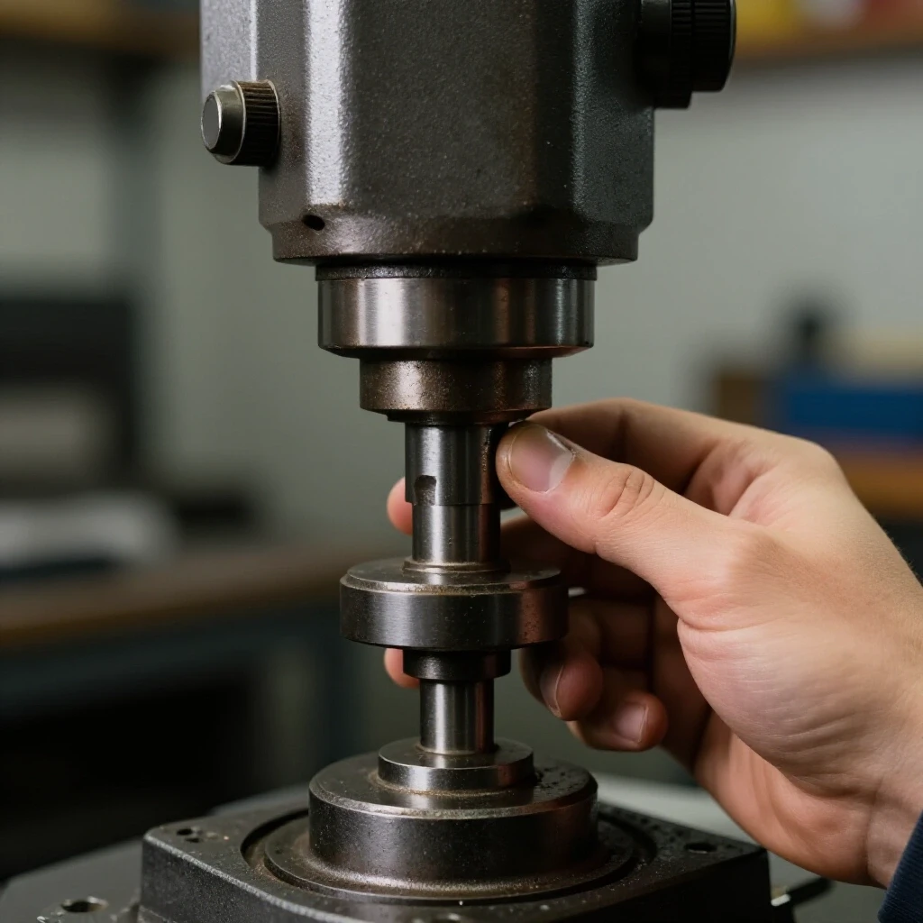
How can I tell if my drill bit is dull without a microscope? You can perform a “thumb test” (with the machine off and unplugged). Gently press your thumb against the cutting edge at a 90-degree angle. A sharp bit will feel like it wants to “catch” your skin’s ridges. A dull bit will feel smooth, like a butter knife. Additionally, if the bit produces fine dust instead of distinct metal chips, it is definitely worn out.
Does tool wear affect the Heat Affected Zone (HAZ) of my weld? Yes. A dull tool generates significantly more friction heat than a sharp one. This heat can “pre-heat” the metal in a localized area, potentially altering its grain structure or causing work-hardening. When you later weld that area, the existing thermal stress combined with the welding heat can make the HAZ more prone to cracking.
What is the most dangerous sign of tool failure? Sudden chipping or “spalling” of the edge is the most dangerous. This usually happens when the tool is overloaded. The broken fragments can become high-velocity projectiles, and the remaining tool edge will instantly “seize” in the work, which can cause the machine to kick back or the workpiece to be thrown from the vise.
Can I use cooling gas to reduce tool wear? While shielding gases like Argon or CO2 are for welding, using a steady flow of compressed air or a mist coolant system is vital for cutting tools. It flushes away chips that would otherwise be “re-cut,” which is a major cause of flank wear and chipping. For most home shops, a 15–20 CFH air blast is enough to keep the cut clear.
How does a built-up edge (BUE) affect my project’s safety? BUE causes the tool to “tear” the metal rather than cut it cleanly. This creates a very rough surface with deep microscopic grooves. These grooves act as “stress risers” where structural cracks can begin. If you are building something that vibrates, like a trailer or a machine frame, these tears can lead to fatigue failure over time.
How often should I check my tools during a large project? I recommend a visual check every 10 to 15 minutes of actual “tool-in-metal” time. If you are working with abrasive materials like stainless steel or high-carbon plate, check every 5 minutes. Consistency is the key to preventing structural metal load capacity issues caused by poor machining.
What should I do if I see a “blue” chip while drilling? Blue chips in steel mean the temperature at the cut has reached approximately 550°F to 600°F. This is too hot for most standard HSS tools and indicates that either your feed rate is too high, your speed is too fast, or the tool is dull. Stop, let everything cool, and inspect the cutting edge for flank wear.
Can a worn tool cause welding porosity? Indirectly, yes. A dull tool “smears” the surface of the metal, often trapping cutting oils or surface oxides underneath a thin layer of distorted metal. When you weld, these trapped impurities gassify and create bubbles in the weld pool, leading to porosity and a weakened joint.
Is it safe to use a tool that has a small chip in the corner? No, especially not for structural work. That chip creates an uneven load on the rest of the tool, which will lead to more chips and eventually a total fracture. It also leaves a jagged finish on your workpiece that can compromise the fit-up of your structural joints.
What PPE should I wear when inspecting tools? Always wear safety glasses, even when the machine is off. Small metal splinters (slivers) can easily be flicked into your eye while you are examining a tool. If you are using a magnifying loupe, ensure your work area is well-lit to avoid eye strain.
How do I know if the heat from a dull tool has ruined my steel? Look for “heat tint” or discoloration. If the steel around your hole or cut has turned dark blue or purple, the localized properties have changed. For critical structural components, you may need to grind away this discolored layer (the “bark”) to reach unaffected metal before welding.
What is the “spindle load” and why does it matter? Spindle load is the amount of torque the motor must produce to keep the tool turning. As a tool wears, the spindle load increases. In a home shop, you can feel this through the handles of your drill press or mill. If the machine feels like it’s “struggling” more than usual, the tool is likely past its useful life.
(This article was written by one of our staff writers, James Harlan. Visit our Meet the Team page to learn more about the author and their expertise.)