How to Restore Old Cast Iron Workshop Machinery (DIY Guide)
Standing in a cold garage before a 1920s drill press, you see more than just a pile of orange scale and seized pulleys. You see a masterpiece of industrial history that was built to last several lifetimes. I have spent the last 18 years in spaces just like that, looking at machines that others labeled as scrap. My journey into vintage machinery restoration began with a rusted-solid South Bend lathe that had sat in a damp barn for three decades. It took me six months to hear its spindle hum again, but that project taught me that patience is the most important tool in any restorer’s chest.
Restoring classic cast iron is a slow, methodical dance between physics and history. These machines were often built with a level of mass and rigidity that modern, lightweight tools simply cannot match. However, bringing them back to factory tolerances requires a disciplined approach to disassembly, cleaning, and alignment. You cannot rush a machine that has been sitting for fifty years. If you force a seized bolt or use the wrong chemical, you risk damaging a component that hasn’t been manufactured since the Great Depression. My goal is to share the systematic framework I use to evaluate, strip, and recalibrate these heavy-duty relics so they can return to work.
Evaluating the Viability of Vintage Machine Rescues
Evaluation is the critical first step where you determine if a piece of equipment is a candidate for a full rebuild or merely a source of parts. It involves a thorough physical inspection of the castings, a check for missing major components, and an assessment of the wear on critical mating surfaces.
When I pull up to a scrap yard or a seller’s driveway, I look for “deal-breakers” first. A cracked main casting is often a sign to walk away, as these structural failures are difficult to address while maintaining precision. I bring a small kit: a flashlight, a stiff wire brush, a shop rag, and a bottle of penetrating oil. I wipe down the “ways”—the flat or V-shaped tracks the machine parts slide on—to look for deep scoring or “ridging.” If the ways are worn down by more than a few thousandths of an inch, the machine will require extensive hand scraping to ever be accurate again.
I also check for “cannibalization.” It is common for previous owners to strip handles, gears, or specialized bolts to fix other machines. While I can fabricate a new shaft or source a common bearing, finding a specific 1930s cast-iron gear guard can be a multi-year hunt. I always ask myself: is the time required to find or make these parts worth the final value of the tool?
Assessing Structural Integrity and Cast Iron Health
Structural health refers to the physical condition of the iron castings, ensuring they are free from deep fractures or “casting rot” caused by extreme environmental exposure. This stage confirms the machine can safely support its own weight and the forces of operation.
Cast iron is remarkably stable, but it is brittle. I use the “ring test” on large castings. If you lightly tap a clean, solid casting with a small brass hammer, it should produce a clear, bell-like ring. A dull “thud” often suggests a hidden crack or a pocket of internal degradation. I pay close attention to the mounting “feet” and the areas around bearing supports, as these are high-stress zones where old machines often failed if they were dropped or over-tightened during a move.
Determining Wear Limits on Sliding Surfaces
Wear limits are the measurable gaps between mating parts that indicate how much of the original metal has been lost to friction over decades of use. Measuring this helps you decide if the machine needs a simple cleaning or a full surface regrind.
I use a dial indicator to check for “slop” or backlash in the lead screws and slides. For a vintage lathe or mill, a backlash of 0.005 to 0.010 inches is often acceptable for hobby work, but anything over 0.020 inches suggests the brass nuts or the screws themselves are nearing the end of their lives. I also look for the original “flaking” or “frosting” marks on the ways. If you can still see these decorative crescent patterns, it means the machine saw very little use, making it a “prime” restoration candidate.
Systematic Disassembly and Documenting Complex Assemblies
Disassembly is the process of taking the machine down to its individual components while recording the exact location and orientation of every part. This stage prevents the “bucket of bolts” syndrome where a restorer forgets how a complex internal gear train fits back together.
I never start a teardown without my camera and a stack of heavy-duty freezer bags. I take a photo before I remove a single screw, then another after the part is off. I use a fine-tip permanent marker to label every bag with the sub-assembly name (e.g., “Headstock Spindle Bolts”). For complex machines, I draw simple 2D sketches in a shop notebook, noting which side of a gear faced “out” or the number of shims found behind a bearing race.
One lesson I learned the hard way: never assume a part is symmetrical. Many vintage machines were hand-fitted at the factory. A pin might look the same on both ends, but it may have a subtle 1-degree taper that only fits one way. If you drive it out the wrong direction, you will wedge it tighter and potentially crack the surrounding casting.
Why Seized Cast Iron Screws Crack Under Force
Seized screws occur when iron oxide (rust) expands in the threads, creating a mechanical bond that is often stronger than the bolt itself. Understanding why they stick allows you to apply the right amount of force and heat without snapping the fastener.
When you encounter a stuck bolt, your first instinct is to grab a longer wrench. Resist this. Cast iron does not give; it snaps. I use a “Thermal Release Plan.” This starts with a 50/50 mix of Automatic Transmission Fluid (ATF) and Acetone, which is a highly effective DIY penetrating oil. I apply it and wait 24 hours. If it still won’t budge, I use a propane torch to heat the casting around the bolt, not the bolt itself. The goal is to expand the hole slightly, breaking the rust bond.
Creating a Parts Inventory and Mapping System
A parts inventory is a structured list or digital sheet that tracks every component, its condition, and what work it requires. This keeps the project organized over the weeks or months the machine is in pieces.
I use a simple spreadsheet for my restorations. It includes columns for the part name, quantity, thread pitch (if a fastener), and status (e.g., “Needs Rust Removal,” “Ready for Paint”).
- Digital Photos: Capture the assembly from three angles.
- Sub-assembly Boxing: Keep all parts for the “Tailstock” in one bin.
- Thread Identification: Measure the diameter and TPI (threads per inch) immediately.
- Condition Notes: Mark parts that need replacement so you can start sourcing them early.
Removing Machinery Rust Without Damaging Base Metal
Rust removal is the chemical or mechanical process of eliminating oxidation while preserving the “skin” of the original cast iron. Using the wrong method can etch the metal or destroy the precision-ground surfaces that the machine needs to function.
For heavy castings, I avoid aggressive grinding wheels. They leave gouges that are impossible to hide. Instead, I prefer “passive” methods. For parts that can fit in a tank, electrolysis is my go-to choice. It uses low-voltage electricity to pull the rust off the part and onto a “sacrificial” piece of scrap metal. For larger surfaces like a table or a bedway, I use chemical chelators or manual scraping with a razor blade and WD-40.
| Method | Best For | Pros | Cons |
|---|---|---|---|
| Electrolysis | Intricate parts, internal cavities | Reaches everywhere, no metal loss | Requires setup, messy “black soup” |
| Evapo-Rust | Precision surfaces, bearings | Non-toxic, very safe for metal | Expensive for large baths |
| White Vinegar | Non-critical heavy iron | Cheap, readily available | Can etch metal if left too long |
| Manual Scraping | Flat bedways, tables | High control, no chemicals | Labor intensive, slow |
Setting Up an Electrolysis Bath for Heavy Castings
Electrolysis is an electrochemical process that uses a DC power source, an electrolyte solution, and a sacrificial anode to convert rust back into a soft sludge. It is the most thorough way to clean complex iron shapes without removing any good metal.
To set this up, I use a plastic tub filled with water and about one tablespoon of “Washing Soda” (sodium carbonate) per gallon. I connect the negative lead of a 12V manual battery charger to the rusted part and the positive lead to a piece of scrap steel (the anode). When I turn it on, bubbles form, and the rust begins to migrate. A typical lathe carriage might take 12 to 24 hours. When it comes out, the part will be covered in a black film (magnetite) that wipes away with a scotch-brite pad, revealing the gray iron beneath.
Manual Rust Removal on Precision Surfaces
Manual removal involves using hand tools and light lubricants to lift surface scale from ground surfaces like ways or tables. This method ensures you do not alter the flatness of the machine while cleaning it.
I never use sandpaper on a machine’s ways. Sandpaper particles can embed themselves in the soft cast iron and act as an abrasive forever. Instead, I use a new, sharp 1-inch razor blade held at a 45-degree angle. I “shave” the rust off the surface, using plenty of light oil as a floating agent. Once the heavy scale is gone, I finish with a fine-grade (gray or white) non-woven abrasive pad. This leaves the original metal intact and ready for a protective coat of paste wax or way oil.
Servicing Babbitt and Sleeve Bearings for Smooth Operation
Bearings are the components that support rotating shafts, such as the main spindle of a lathe or drill press. Many vintage machines use “plain” bearings made of bronze or Babbitt rather than modern ball bearings.
Babbitt is a soft, white-metal alloy (usually tin, antimony, and copper) that was poured directly into the machine’s casting. If the spindle feels loose, you may not need to replace the bearing. Often, you can “take up the slack” by removing thin metal shims from the bearing cap. I aim for a clearance of 0.001 to 0.0015 inches for every inch of spindle diameter. This allows enough room for a thin film of oil to support the shaft without letting it vibrate.
Measuring and Adjusting Bearing Clearances
Bearing clearance is the tiny gap between the shaft and the bearing wall that allows for lubrication. Proper adjustment prevents the bearing from overheating while ensuring the machine cuts accurately.
I use “Plastigage” to check these tolerances. It is a tiny plastic thread that you place on the shaft before tightening the bearing cap. When you remove the cap, you measure how much the thread flattened. If the gap is too wide, I peel off one layer of the brass shim stack. If it’s too tight, the bearing will “seize” as it heats up. I always test the spindle by hand; it should spin freely but have no detectable “clunk” when you push and pull on it.
Lubrication Requirements for Vintage Spindles
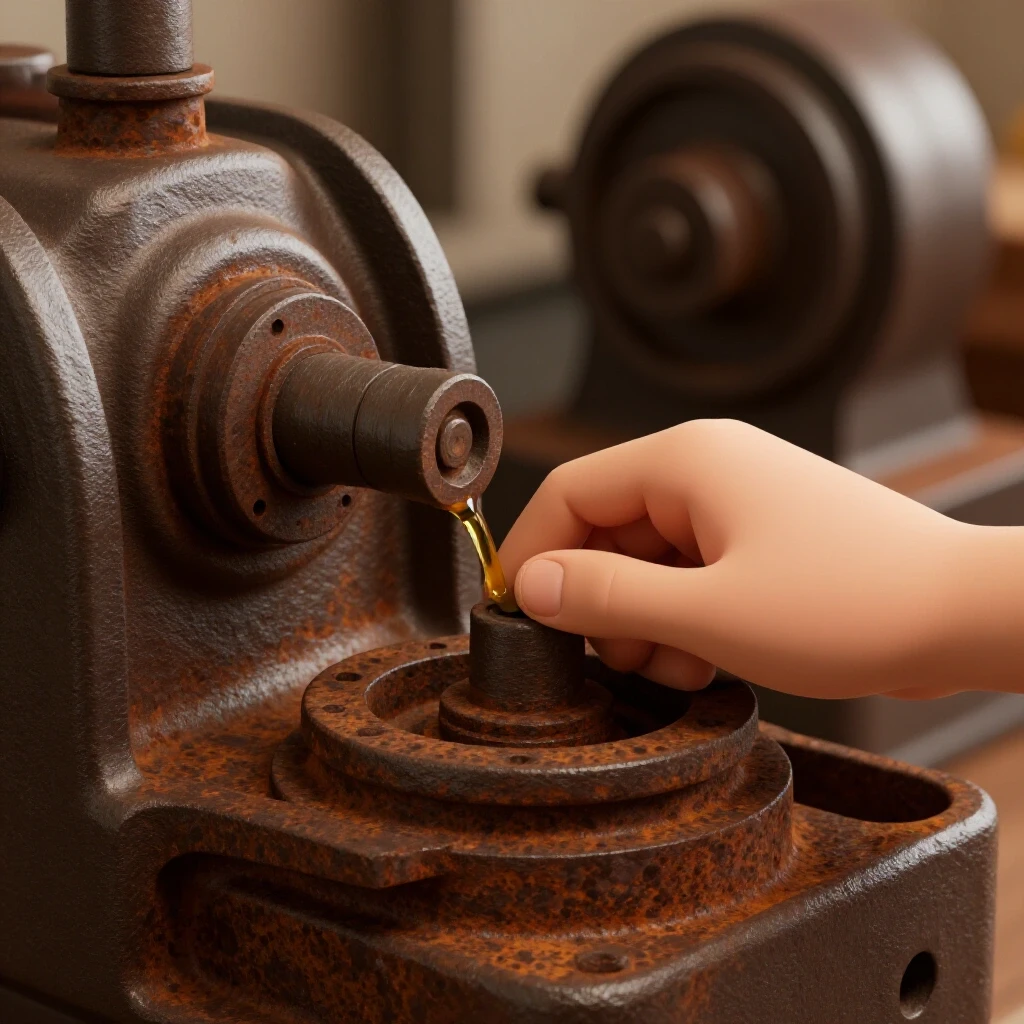
Lubrication in old machines is not a “set and forget” system. These tools often use “total loss” lubrication, meaning the oil slowly drips out and must be constantly replenished through oil cups or felt wicks.
You cannot use modern automotive oil in these machines. Car oil contains detergents designed to keep particles in suspension, which is bad for an old machine without a filter. I use “Non-Detergent” (ND) oils or specific “ISO” rated oils. For most spindles, an ISO 32 or ISO 46 hydraulic oil works well. For the sliding ways, I use “Way Oil” (ISO 68), which contains “tackifiers” that help the oil stick to vertical surfaces rather than just running off.
Managing Obsolete Fasteners and Legacy Thread Patterns
Fasteners in vintage machinery often follow standards that predated the modern Unified Thread Standard (UTS). Identifying these obsolete patterns is essential for replacing missing bolts or repairing stripped holes.
If you are working on a pre-war machine, you might encounter Whitworth threads or “bastard” pitches that don’t match anything at the local hardware store. I keep a thread pitch gauge and a micrometer handy. If I find a bolt with a 1/2-inch diameter but 12 threads per inch (modern is 13), I know I’m dealing with an older standard. In these cases, I don’t try to force a modern bolt in. I either source a vintage replacement from a machinery forum or I turn a new bolt on my other lathe.
Identifying Whitworth and Non-Standard Pitches
Non-standard pitches are thread counts that were common in the 19th and early 20th centuries but have since been phased out. Correct identification prevents you from “cross-threading” and ruining a historic casting.
- Measure Diameter: Use a micrometer to get the major diameter.
- Count Threads: Use a pitch gauge; check both Metric and Imperial sets.
- Check the Angle: Older British threads (Whitworth) have a 55-degree angle, while modern ones have 60 degrees.
- Reference Tables: Use a copy of the “Machinery’s Handbook” (older editions are better) to look up obsolete standards like the “Sellers” thread.
Restoring Precision Through Hand Scraping and Alignment
Hand scraping is the process of using a sharpened tungsten-carbide tool to manually remove high spots from a metal surface. This is how machines were originally made “flat” at the factory, and it is how we restore them to high precision today.
When a machine’s ways are worn, they become “swaybacked” or low in the middle. To fix this, I use a “Master Straightedge” and “Prussian Blue” (a non-drying dye). I coat the straightedge with a very thin layer of blue dye and rub it against the machine’s surface. The dye transfers only to the “high spots.” I then use a hand scraper to shave those blue spots away. I repeat this hundreds of times until I get a consistent pattern of “contact points.”
The Goal of Points Per Inch (PPI)
Points Per Inch (PPI) is a measurement of how many tiny contact spots exist in a square inch of the surface. A higher PPI means the load is distributed over more area, resulting in less wear and better oil retention.
For a general-purpose workshop machine, I aim for 10 to 15 PPI. For a high-precision toolroom lathe, I might go up to 20 or 25 PPI. You don’t want a perfectly smooth, mirror-like surface. The tiny “valleys” between the scraped points act as reservoirs for oil. Without these valleys, the sliding parts would squeeze all the oil out, creating a vacuum that causes “stiction” and rapid wear.
Aligning the Machine to Level
Alignment is the final step where you ensure the machine’s various axes are parallel or perpendicular to each other. A “level” machine is the foundation for all accurate work.
I use a “Master Precision Level” (accurate to 0.0005 inches per foot) to set up the machine. I don’t care if the machine is level relative to the earth’s center; I care that the bed is not “twisted.” I place the level across the ways at the headstock end, then move it to the tailstock end. If the bubble moves, the bed is twisted. I use steel shims under the machine’s feet to “untwist” the casting until the level stays centered at every point along the bed.
Practical Tracking and Testing Framework
A successful restoration ends with a “run-in” period where the machine is tested under light load to ensure everything is seating correctly. I use a specific checklist to track this final phase.
- Initial Spindle Run: Run the spindle at its lowest speed for 30 minutes. Check the bearing temperature with an infrared thermometer. It should be warm (around 100-110°F) but never hot to the touch.
- Oil Flow Verification: Ensure oil is reaching all designated ports. Look for the “weeping” of clean oil at the ends of the bearings.
- Accuracy Test: Mount a ground test bar in the spindle and use a dial indicator to check for “runout” (wobble). A good restoration should show less than 0.001 inches of runout.
- Nut and Bolt Re-torque: After the first few hours of use, go back and check every fastener. Vibration can cause newly cleaned threads to settle.
Frequently Asked Questions
Can I use a pressure washer to clean an old cast iron machine? I strongly advise against this. Pressure washers force water into bearing races, internal gearboxes, and porous iron surfaces. This can cause “flash rust” in areas you cannot reach to dry. Use a degreaser and shop rags instead.
How do I know if a machine is too worn to restore? Check the “ways” near the headstock. If there is a visible “step” or a ridge that you can catch with your fingernail, the machine has significant wear. If the ridge is deeper than 0.010 inches, the machine will require professional grinding or weeks of hand scraping to be accurate.
Is it safe to use vinegar for rust removal on precision parts? Vinegar is an acid. While it removes rust, it also eats “good” metal if left too long. For precision surfaces like a lathe bed or a micrometer dial, use a pH-neutral chelator like Evapo-Rust to avoid etching the surface.
What is the best way to paint a restored machine? After stripping to bare metal, use a high-quality “High Solids” primer. For the topcoat, an oil-resistant machinery enamel is best. I prefer brush-painting with a high-quality natural bristle brush; it leaves a thick, durable coat that mimics the original factory finish better than a thin spray-can layer.
Where can I find manuals for machines that are 80 years old? Websites like “VintageMachinery.org” and “Lathes.co.uk” host massive digital archives of original manufacturer manuals and catalogs. These are invaluable for identifying missing parts or understanding complex internal assemblies.
Can I replace Babbitt bearings with modern ball bearings? Usually, no. The castings were designed for the specific dimensions and load-bearing characteristics of Babbitt. Converting to ball bearings often requires extensive machining of the main headstock, which can weaken the tool. It is better to “re-pour” or adjust the original plain bearings.
How do I remove a pulley that is rusted to a shaft? Apply penetrating oil for several days. Use a “puller” tool, but place a thick piece of scrap metal between the puller’s bolt and the shaft to avoid “mushrooming” the shaft end. If it still won’t move, use localized heat on the pulley hub.
What should I do if I find a crack in a cast iron handle? For non-structural parts like handles or handwheels, you can sometimes find a replacement on eBay or at a machinery swap meet. If the part is unique, some restorers use “cold-fixing” methods like pins, but for a hobbyist, sourcing a donor part is usually the safest path.
How often should I oil my restored machine? Every time you use it. Vintage machines were designed to be oiled daily. I make it a habit to “oil around” the entire machine before I ever flip the power switch.
What is “stiction” and how do I prevent it? Stiction is “static friction.” It happens when two flat metal surfaces squeeze out all the oil and “lock” together. You prevent it by ensuring your surfaces have a proper scraped finish (PPI) and by using a dedicated Way Oil with “tackifiers.”
Is it worth restoring a machine with a missing motor? Yes. Motors are “consumable” parts. Most old machines used standard NEMA frame motors that are easily replaced with modern equivalents. The value is in the heavy iron castings and the precision of the mechanical parts, not the motor.
How can I identify the age of my machine? Look for a serial number, usually stamped into the bedways at the far end or on a brass nameplate. You can then cross-reference this number with online databases or manufacturer records to find the exact year of production.
(This article was written by one of our staff writers, Richard Beaumont. Visit our Meet the Team page to learn more about the author and their expertise.)