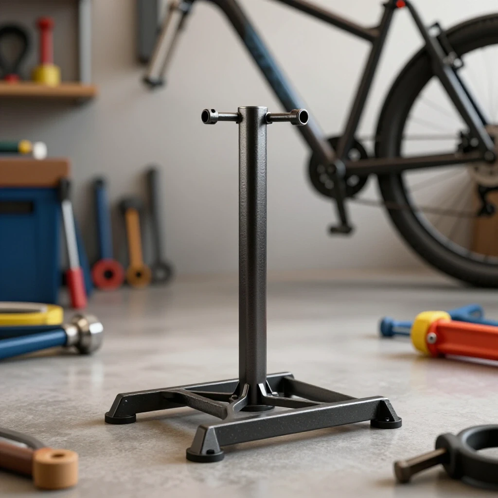
How to Safely Weld a Trailer Hitch Receiver Plate (Guide)
I remember the first time I tried to join a heavy-duty receiver tube to a mounting plate. I had spent two hours measuring, scribing lines with a carbide tip, and ensuring every cut was dead square. I clamped it down to my bench, ran a beautiful, hot bead along one side, and felt like a pro. Then, I unclamped it. The heat had pulled the tube nearly an eighth of an inch out of alignment. That “perfect” assembly was now a lopsided piece of scrap. It was a humbling lesson in the physics of thermal expansion and the raw power of weld shrinkage.
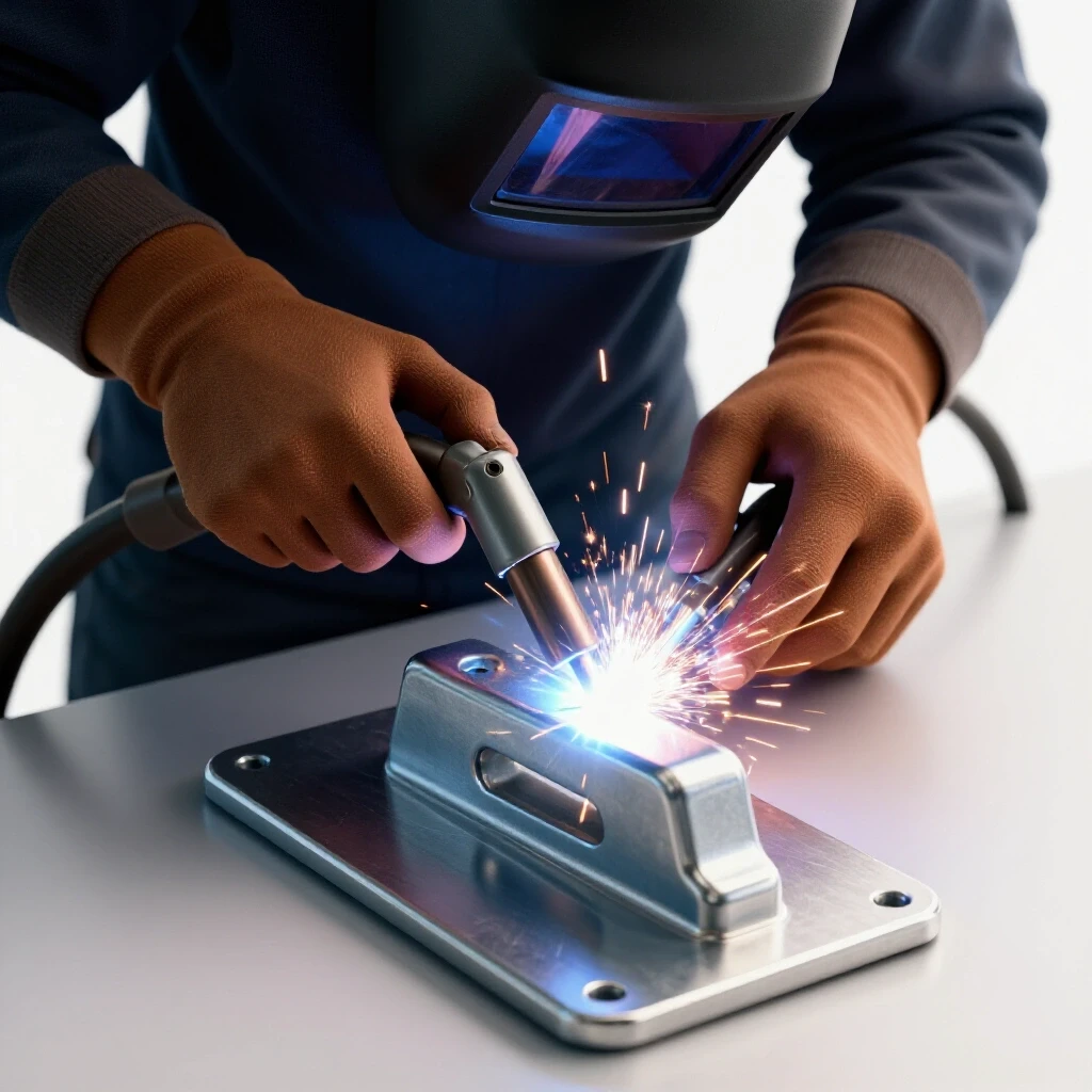
In my thirteen years as a prototype technician and fabricator, I’ve learned that successful custom fabrication projects aren’t just about how steady your hand is. They are about how well you anticipate the metal’s movement. When you are joining thick-walled square tubing to a flat steel plate, you are dealing with significant masses of metal that want to warp as they cool. My goal is to walk you through the structural logic and physical techniques required to keep your assemblies straight, strong, and true to your original blueprints.
Designing Your Component Layout and Material Selection
Material selection and layout planning involve choosing the correct steel grades and thicknesses while mapping out the exact placement of every joint. For structural utility components, this means using ASTM A36 mild steel or similar structural grades that offer predictable welding characteristics. A proper layout ensures that the receiver tube sits centered and square on the plate.
When I start a new build, I always begin with a clean workspace and a fresh scribe. For a standard receiver setup, you are typically looking at a 2-inch ID (inside diameter) cold-drawn seamless tube with a 1/4-inch or 5/16-inch wall thickness. The mounting plate should match or exceed this thickness to ensure the weld doesn’t blow through or cause excessive warping in the thinner material.
Before the first spark flies, I check the “fit-up.” In the world of custom fabrication, fit-up refers to how tightly the two pieces of metal meet. A gap larger than 1/16th of an inch can lead to excessive weld volume, which increases heat input and, consequently, distortion. I use a machinist’s square to verify that the end of the tube is cut at exactly 90 degrees. If the cut is off by even a degree, the “lever arm” of the tube will magnify that error over its length.
| Material Component | Recommended Specification | Purpose |
|---|---|---|
| Receiver Tube | 2″ ID, 1/4″ or 5/16″ Wall | Provides structural housing |
| Mounting Plate | 1/2″ or 5/8″ A36 Steel | Acts as the structural base |
| Welding Wire/Rod | ER70S-6 (MIG) or E7018 (Stick) | Matches base metal tensile strength |
| Cleaning Method | Flap Disc (60 Grit) | Removes mill scale for better penetration |
Precision Cutting and Kerf Management for Square Assemblies
Precision cutting is the act of removing material to specific dimensions while accounting for the “kerf,” which is the width of the material removed by the cutting tool. Managing this allowance ensures that the final dimensions of your assembly match your blueprints. Inaccurate cuts are the primary cause of poor fit-up and structural weakness in DIY projects.
I’ve seen many builders forget to account for the thickness of their saw blade. If you’re using a dry-cut chop saw, your kerf might be 3/32 of an inch. If you’re using a plasma cutter, it could be 1/16 of an inch depending on your tip and speed. If you don’t account for this, your receiver tube ends up shorter than intended, or your mounting plate ends up undersized.
When cutting the receiver tube, I always mark my line and then cut on the “waste side” of that line. This leaves the full dimension of the part intact. After the cut, I use a belt sander or a flap disc to “true up” the face. A perfectly flat face on the end of the tube is non-negotiable. If the face is wavy, the tube will lean toward the high spots as the weld cools, ruining your alignment.
- Dry-Cut Saw Kerf: 0.090″ to 0.125″
- Abrasive Saw Kerf: 0.125″ to 0.187″
- Bandsaw Kerf: 0.035″ to 0.050″
- Plasma Cutter Kerf: 0.040″ to 0.060″
Managing Thermal Distortion in Heavy Plate
Thermal distortion is the physical warping of metal caused by the uneven heating and cooling cycles of the welding process. As the weld puddle cools, it contracts, pulling the surrounding metal toward the center of the bead. Understanding this “weld pull” is essential for maintaining the dimensional tolerances of your custom fabrication projects.
Think of a weld like a cooling rubber band. When the molten steel solidifies, it shrinks by about 1% to 3% in volume. This doesn’t sound like much, but when that shrinkage happens across a 2-inch tube, it exerts thousands of pounds of force. This is known as angular distortion. If you weld only one side of the tube, the top of the tube will tilt toward that weld.
To combat this, I use a “heat balance” approach. If I put a bead on the left side, I immediately follow it with a bead on the right side. This creates opposing forces that help keep the tube centered. However, you can’t just wing it; you need a strategy. I often use a “skip welding” technique where I move around the joint to prevent any single area from becoming excessively heat-soaked.
The Role of Fixturing Jigs and Workshop Fixtures
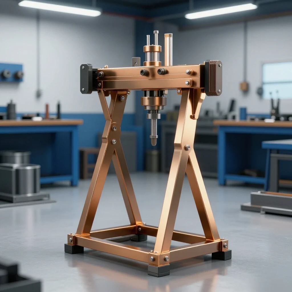
A fixturing jig is a temporary structure or tool used to hold workpieces in a fixed position during the welding process. These workshop jigs and fixtures act as a mechanical restraint, preventing the metal from moving as it undergoes thermal expansion and contraction. Proper fixturing is the most effective way to ensure a project stays square.
I never weld a receiver plate “freehand.” I use a thick steel welding table as my primary fixture. If you don’t have a dedicated fixture table, you can build a temporary one using heavy C-channels or I-beams. The goal is to clamp the mounting plate down so firmly that it cannot bow. I use heavy-duty F-clamps or Bessey clamps, placing them every 3 to 4 inches around the perimeter of the plate.
For the receiver tube itself, I often build a “V-block” jig. This is simply two pieces of angle iron welded to a base plate that cradles the square tube and keeps it perfectly perpendicular to the mounting plate. By locking the tube into a V-block, I eliminate the side-to-side wobble that often happens when you’re trying to tack the piece into place.
- Clean the fixture surface: Any slag or debris will throw off your squareness.
- Position the plate: Center the mounting plate on the fixture and clamp it at all four corners.
- Center the tube: Use a centering head or a combination square to find the exact midpoint.
- Secure the tube: Use a magnetic square or a specialized jig to hold the tube upright.
- Double-check: Measure from the edge of the plate to the tube on all four sides to ensure +/- 1/16th inch tolerance.
Structural Tacking and Alignment Checks
Tack welding involves placing small, temporary beads at key points to hold the assembly together before the final welding passes. These tacks must be strong enough to resist the initial pull of the cooling metal but small enough to be incorporated into the final bead. Accurate tacking is the foundation of a straight build.
I see a lot of beginners use tiny “bird poop” tacks that pop the moment the metal starts to move. For 1/4-inch material, your tacks should be about 1/4-inch to 3/8-inch long and have good penetration. I prefer to place four tacks: one in the center of each of the four sides of the square tube.
After the first two tacks (on opposite sides), I stop and check for square. If the tube has pulled slightly, I can usually “tap” it back into place with a dead-blow hammer before placing the final two tacks. This is the last chance to fix your alignment. Once all four sides are tacked, I re-verify the vertical alignment with a machinist’s square on all four faces. If it’s out by more than 1/16th of an inch, I cut the tacks and start over.
Executing the Weld Sequence for Maximum Strength
A weld sequence is the specific order in which beads are applied to a joint to distribute heat evenly and minimize distortion. By following a strategic weld sequencing layout, you can cancel out the pulling forces of individual beads. This is critical for maintaining the structural integrity of the receiver-to-plate interface.
When I’m ready for the final passes, I don’t just start at one corner and go all the way around. That’s a recipe for a warped plate. Instead, I use a “cross-pattern” or “star-pattern” sequence. I start by welding a 1-inch segment on the top side, then move to the bottom side and weld a 1-inch segment there. Then I move to the left, then the right.
For a heavy receiver plate, I typically use a multi-pass fillet weld. The first pass (the root pass) ensures deep penetration into the corner where the tube meets the plate. The subsequent passes (the cover passes) build up the “throat” of the weld to the required thickness. In my shop, I aim for a weld leg length that matches the thickness of the thinner material—usually 1/4 inch.
| Sequence Step | Action | Logic |
|---|---|---|
| Step 1 | 1-inch bead, Side A | Initiates the joint without overheating |
| Step 2 | 1-inch bead, Side C (Opposite) | Counteracts the pull from Side A |
| Step 3 | 1-inch bead, Side B (Adjacent) | Stabilizes the lateral axis |
| Step 4 | 1-inch bead, Side D (Opposite) | Completes the initial structural ring |
| Step 5 | Fill remaining gaps in reverse order | Distributes final heat load evenly |
Heat Management and Interpass Temperature Control
Interpass temperature control is the practice of monitoring the temperature of the metal between welding passes. If the steel becomes too hot, the heat-affected zone (HAZ) expands, which can weaken the material and increase the severity of the warping. Managing heat is a balance between penetration and preservation.
During these custom fabrication projects, I keep a temp-stick or an infrared thermometer nearby. For mild steel, I try to keep the interpass temperature below 500 degrees Fahrenheit. If the plate starts to glow dull red, I stop. I walk away, grab a coffee, and let the assembly air-cool. Never quench a structural weld with water; this can cause the steel to become brittle and crack.
Using a copper or aluminum heat sink can also help. I sometimes clamp a thick block of copper next to the weld zone. Copper absorbs heat much faster than steel, acting like a thermal sponge. This keeps the heat localized to the joint and prevents it from migrating across the entire mounting plate, which helps keep the plate flat.
Quality Assurance and Post-Weld Inspection
Post-weld inspection is the process of verifying that the completed weld meets structural standards and dimensional requirements. This includes visual checks for defects like undercut, porosity, or cold lap, as well as checking that the assembly remained square throughout the process. It is the final step in ensuring a safe, durable build.
Once the metal has cooled naturally to room temperature, I perform a visual inspection. I look for “undercut,” which is a groove melted into the base metal next to the toe of the weld. This acts as a stress riser and can lead to failure. I also look for “cold lap,” where the weld metal simply sits on top of the plate without actually fusing to it.
If the project is critical, I’ll use a dye-penetrant test. I spray a red dye on the weld, wipe it off, and then apply a white developer. If there are any microscopic cracks, the red dye will “bleed out,” showing me exactly where the problem is. Finally, I put the square back on the tube. If I’ve followed my sequencing and fixturing correctly, the tube should still be within my 1/16th-inch tolerance.
- Visual Inspection: Check for consistent ripple pattern and lack of holes (porosity).
- Dimensional Check: Verify the tube is still square to the plate in both X and Y axes.
- Weld Profile: Ensure the fillet weld is slightly convex, not concave.
- Penetration Check: Ensure the weld has “consumed” the corners of both the tube and the plate.
Common Pitfalls in Utility Fabrication
Even experienced builders run into trouble. One of the most common mistakes is “over-welding.” It’s tempting to think that more weld is always better, but excessive weld metal just adds more heat and more distortion without necessarily adding more strength. If your weld throat is thicker than the base metal, you’ve reached the point of diminishing returns.
Another issue is “arc blow,” which often happens when welding into deep corners or near heavy magnets. The magnetic field deflects the arc, causing splatter and poor penetration. If this happens, I move my ground clamp closer to the weld or switch to an AC (alternating current) setting if I’m stick welding.
Lastly, never underestimate the importance of cleaning. I’ve seen beautiful welds fail because the builder didn’t grind off the mill scale (the dark grey coating on new steel). Mill scale is an insulator and contains impurities that can cause “porosity”—tiny gas bubbles trapped in the weld that act like Swiss cheese in your structural joint.
Tracking Your Build Progress
To stay organized during these builds, I recommend keeping a simple log. This helps you track your costs and learn from each project. For a receiver plate assembly, your log might look like this:
- Material Cost: $45 (Tube and Plate)
- Prep Time: 45 minutes (Cutting and Grinding)
- Layout Time: 20 minutes (Scribing and Squaring)
- Welding Time: 30 minutes (Tacking and Sequencing)
- Consumables: 1/4 roll of .035 wire, 1/8 tank of C25 gas.
- Final Tolerance: +1/32″ (Success)
By documenting these metrics, you begin to see patterns in how different materials behave. You’ll learn that a certain sequence works better for 1/2-inch plate than it does for 1/4-inch plate. This data-driven approach is what separates a “backyard welder” from a true fabricator.
Moving Forward with Your Fabrication
Building a straight, strong receiver assembly is a milestone in any DIYer’s journey. It requires a blend of geometry, physics, and manual skill. By focusing on accurate square cuts, robust workshop jigs and fixtures, and disciplined weld sequencing, you can overcome the natural tendency of metal to warp and distort.
The next time you stand at your welding bench, remember that the heat is your tool, not your enemy. Control it with clamps, manage it with sequences, and respect it with patience. Your projects will be stronger, straighter, and more professional as a result.
Frequently Asked Questions
What is the best welding process for a receiver plate? For most DIY builders, MIG (GMAW) with a solid wire and 75/25 shielding gas is the most efficient. It provides clean, deep penetration and is easier to control for heat input. However, Stick (SMAW) welding with a 7018 rod is also an excellent choice for structural projects, especially if you are working outdoors or on thicker material where deep penetration is paramount.
How do I prevent the mounting plate from bowing? The best way is to clamp the plate to a much thicker “sacrificial” piece of steel or a dedicated fixture table. You can also “pre-bend” the plate slightly in the opposite direction of the weld pull, though this requires significant experience to judge the correct amount of offset.
What should I do if the tube pulls out of square after tacking? If the tube is out of square after tacking, do not proceed with the final weld. Use a thin cutoff wheel to carefully cut the tacks on the side the tube is leaning toward. Re-align the tube, using a hammer if necessary, and re-tack. It is much easier to fix a tack than a full bead.
Why is mill scale such a problem for welding? Mill scale is a layer of iron oxide that forms during the hot-rolling process. It has a higher melting point than the underlying steel and can trap oxygen and moisture. This leads to “lack of fusion” and porosity, which significantly weakens the structural integrity of the joint. Always grind the weld area to shiny metal.
How large should the fillet weld be? A general rule of thumb in structural welding is that the “leg” of the fillet weld should be equal to the thickness of the thinnest material being joined. If you are welding a 1/4-inch wall tube to a 1/2-inch plate, your weld leg should be 1/4 inch.
Can I weld this in one single pass? While a high-amperage MIG machine can lay down a 1/4-inch bead in one pass, it is often better to use two or three passes. This allows you to manage the heat better and ensures that the root of the joint is fully fused before you add the bulk of the filler metal.
What is “undercut” and how do I fix it? Undercut is a groove or valley at the edge of the weld bead where the base metal has been melted away but not replaced by filler metal. It is usually caused by too much heat or an incorrect torch angle. To fix it, you must clean the area and run a small “stringer” bead to fill the groove.
How long should I wait between weld passes? You should wait until the metal is cool enough to touch (briefly) with a gloved hand, or check it with a thermometer to ensure it is below 500°F. If you can see the metal glowing, it is too hot for the next pass.
Do I need to weld the inside of the receiver tube? Generally, no. Most receiver tubes are welded only on the outside where they meet the plate. Welding the inside can interfere with the fitment of the hitch accessory and is difficult to do properly without specialized equipment. A full-penetration exterior fillet weld is typically sufficient.
What is the “Heat Affected Zone” (HAZ)? The HAZ is the area of base metal that did not melt but had its microstructure and properties altered by the heat of welding. This area is often slightly weaker than the base metal or the weld itself. Minimizing the HAZ by controlling heat input is key to a strong build.
(This article was written by one of our staff writers, Robert Kline. Visit our Meet the Team page to learn more about the author and their expertise.)