How to Stiffen Flexible Sheet Metal Motor Mounts (DIY Fix)
I have spent the last 18 years in fabrication shops, and if there is one thing I have learned, it is that a machine is only as good as its foundation. I remember a specific job involving a custom-built ventilation system where the motor kept throwing belts. On paper, everything was aligned. The pulleys were co-planar within 0.010 inches, and the tension seemed correct. However, every time the motor reached its operating RPM, the whole assembly began to howl. It was a classic case of a structural support that lacked the necessary stiffness to handle operational torque.
When a motor support flexes, it creates a cascade of failures. You see tool chatter in machining centers, premature bearing wear, and belt misalignment. Most people try to fix this by over-tensioning belts or adding more bolts, but those are just Band-Aids. To solve the problem, you have to look at the geometry of the metal itself. Thin sheet metal is excellent for weight reduction, but it is notoriously poor at resisting torsional or twisting forces.
In this guide, I will walk you through the systematic process of diagnosing structural flex and the practical workshop methods I use to reinforce these supports. We will focus on manual techniques—cutting, folding, and welding—that turn a flimsy bracket into a rigid component. This is about using logic and physics to stop the vibration before it starts.
Pinpointing Structural Weakness in Fabricated Brackets
Structural diagnosis is the process of identifying exactly where a material deforms under load by applying controlled force and measuring the resulting displacement. It requires isolating the mount from the rest of the machine to ensure you are not chasing a ghost in the bearings or the frame.
Before you reach for the welder, you need data. I start by mounting a magnetic base dial indicator to a fixed, non-moving part of the machine frame. Place the tip of the indicator on the motor housing itself. With the power off, apply a manual load to the motor in the direction of the belt pull or the rotational torque. If you see the needle jump more than 0.005 inches under moderate hand pressure, your mount is the primary culprit.
A common issue I encounter is “oil-canning.” This happens when a flat area of sheet metal pops back and forth like the bottom of an old oil can. It occurs because the flat surface has no structural “memory” or shape to resist bending. You can find these spots by pressing your thumb into the center of the flat panels while the motor is running (carefully, of course). If the vibration changes pitch or the noise drops, you have found your weak point.
- Observation: Look for blurred edges on the mount while it runs, which indicates high-frequency vibration.
- Isolation: Remove the belts or drive links to see if the flex is caused by the motor’s internal balance or the external load.
- Measurement: Use a feeler gauge between the mount and the base to check for “soft foot,” where one corner isn’t sitting flush.
The Geometry of Rigidity: Why Flat Plates Fail
Understanding the relationship between material shape and its resistance to bending is fundamental to solving fabrication errors. A flat piece of 11-gauge steel is easy to bend by hand, but that same piece of steel becomes incredibly stiff once you introduce a 90-degree fold.
The reason a flat plate fails in a motor application is its low moment of inertia. In simple shop terms, there is no material “depth” to resist the force. When I am troubleshooting a vibrating motor, I often find that the builder used a thick plate but left it entirely flat. You can often achieve more rigidity with a thinner gauge of metal that has been formed into a C-channel or a box section than you can with a heavy, flat slab.
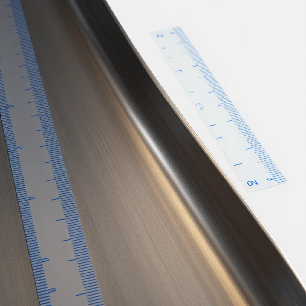
Building on this, the goal of any reinforcement is to move material away from the neutral axis of the bend. This is why I prefer adding flanges or lips to the edges of a support. If you have a flat motor plate, even a small 1/2-inch lip bent at a right angle along the edges will increase the stiffness significantly.
| Reinforcement Method | Primary Benefit | Difficulty Level |
|---|---|---|
| Edge Flanging | Increases longitudinal stiffness | Moderate (Requires brake) |
| Triangular Gusseting | Prevents corner “folding” | Low (Basic cutting/welding) |
| Doubler Plates | Reduces localized “oil-canning” | Low (Plug welding) |
| Box Sectioning | Maximum torsional resistance | High (Requires fit-up) |
| Dimple Die Flaring | Adds strength via cold-working | Moderate (Requires press) |
Implementing Edge Flanges and Folds
Edge flanging is the process of bending the perimeter of a sheet metal part to create a structural “rib” that resists bending along the length of the fold. It is one of the most effective ways to stabilize a vibrating motor platform without adding excessive weight.
If you are working with an existing mount that is already welded in place, you cannot easily put it in a sheet metal brake. In these cases, I fabricate “bolt-on” or “weld-on” flanges. I take a strip of 1/8-inch flat bar and weld it vertically to the edge of the horizontal motor plate. This creates an L-shape profile.
Interestingly, the height of this flange is more important than its thickness. A 1-inch tall flange made of 14-gauge steel will often provide more rigidity than a 1/4-inch thick flat bar welded flat against the surface. When welding these flanges, I use a staggered stitch pattern. A continuous bead on thin sheet metal often leads to warping, which pulls the motor out of alignment. I typically weld 1 inch, skip 3 inches, and repeat, allowing the metal to cool between passes.
- Step 1: Measure the length of the unsupported edge.
- Step 2: Cut a strip of matching material at least three times the thickness of the base plate in height.
- Step 3: Tack weld the strip at a 90-degree angle to the edge.
- Step 4: Check for alignment and then complete the stitch welds.
Using Triangular Gussets to Stop Parallelogramming
Gusseting involves placing triangular braces in the corners where two planes meet to prevent the angle from changing under load. This is essential for motor mounts that are cantilevered or “hung” off the side of a machine frame.
I once worked on a large belt-driven sander where the motor was mounted on a simple L-bracket. Every time the sander hit a heavy knot in the wood, the motor would dip, causing the belt to slip. The bracket was literally opening up like a hinge. The fix was a pair of simple triangular gussets welded into the “V” of the bracket.
When you layout a gusset, ensure the grain of the metal (if using cold-rolled) runs parallel to the longest side for maximum strength. I prefer to “cope” or notch the point of the triangle where it meets the corner of the bracket. This prevents the weld from bunching up in the corner and allows for better penetration on the flat surfaces.
Troubleshooting Weld Porosity in Reinforcement Joints
Weld porosity is a defect characterized by small holes or pits in the weld bead, caused by trapped gas. When reinforcing a motor mount, porosity is a disaster because it creates stress risers that will eventually lead to fatigue cracking under the motor’s vibration.
If you are seeing “Swiss cheese” in your welds while adding braces, you need to stop and isolate the cause. In my experience, the most common culprit in a repair scenario is surface contamination. Motor mounts are often coated in oil, belt dust, or old paint. Even a tiny amount of grease trapped between a doubler plate and the main mount will vaporize and blow holes in your weld.
Another factor is shielding gas coverage. If you are welding in a drafty shop, the wind can blow away your argon/CO2 mix. I keep my flow rate between 15 and 20 CFH (cubic feet per hour) for most shop work. If I still see porosity, I check the nozzle for “spatter” buildup, which can cause turbulence in the gas flow.
- Cleanliness: Use a flap disc to grind back to shiny metal at least 1 inch away from the weld zone.
- Gas Flow: Check for leaks in the regulator or the lead.
- Technique: Maintain a tight arc length; a long arc is more susceptible to atmospheric contamination.
Box Section Construction for Maximum Torsion Resistance
Box sectioning is the process of transforming an open-shaped bracket into a closed, four-sided structure. This is the gold standard for stopping a motor from twisting or “walking” under high startup torque.
Think of a piece of C-channel. You can twist it with a large pipe wrench relatively easily. Now, weld a flat plate across the open side of that C-channel. You have created a box. The resistance to twisting (torsional rigidity) increases exponentially. For heavy motors or those with high-inertia starts, I almost always box in the support.
When boxing a mount, you must consider access to the mounting bolts. I often drill “access holes” in the box section so I can reach the nuts with a socket. These holes should be flared with a dimple die if possible, as the flare adds back the strength lost by removing the material.
Adding Doubler Plates to Dampen Resonant Harmonics
A doubler plate is a second layer of material added to a specific area to increase thickness and change the resonant frequency of the part. This is particularly useful for eliminating that annoying “hum” or “buzz” that happens at specific motor speeds.
Every structure has a natural frequency where it likes to vibrate. If your motor’s RPM matches that frequency, the vibration will amplify until something breaks. By laminating a doubler plate to the center of a flat span, you change the mass and stiffness, effectively “tuning” the vibration out of the operational range.
To install a doubler, I use plug welding. I drill 5/16-inch holes every 2 inches in the doubler plate. I then clamp the plate tightly to the mount and weld through the holes, fusing the two layers together. This is much more effective than just welding the edges, as it ensures the two plates act as a single, thick unit rather than two thin sheets rubbing against each other.
- Identify the “hot spot” of vibration using a smartphone vibration analyzer app.
- Cut a doubler plate that covers at least 60% of the vibrating surface.
- Drill a grid of plug weld holes.
- Clamp and weld from the center outward to minimize trapped air and warping.
Correcting Alignment Errors After Fabrication
Welding heat causes metal to expand and contract, which can easily pull a motor mount out of alignment. A mount that is 1/16 of an inch out of square can ruin a set of belts in a week.
After I finish stiffening a mount, I always perform a “post-weld alignment check.” I use a straightedge across the faces of the pulleys. If the mount has warped, I don’t try to “cold-bend” it back into place with a sledgehammer. That just introduces internal stress that will crack later. Instead, I use shims.
Hardened steel shims are your best friend here. If the motor is tilted, I place shims under the low feet until the pulley faces are perfectly parallel. I aim for a tolerance of 0.002 inches per inch of pulley diameter. If the misalignment is severe, I might use “heat shrinking”—applying localized heat with a torch to the opposite side of the warp—to pull the metal back into position.
Managing Tool Chatter and Spindle Backlash via Rigidity
In a machining context, a flexible motor mount is often the hidden cause of tool chatter. Chatter is a resonant vibration that occurs when the cutting tool and the workpiece bounce off each other at high speeds, leaving a wavy finish.
If your lathe or mill is producing a poor surface finish, check the motor mounts first. If the motor can move, the belt tension fluctuates. This fluctuation causes the spindle speed to micro-vary, which triggers chatter. By stiffening the motor platform, you stabilize the spindle torque.
I also look for backlash in the adjustment screws. Many motor mounts use a threaded rod to set belt tension. If that rod is thin or the threads are worn, the motor can “bounce” on the screw. I replace thin tensioning rods with larger diameter Grade 8 all-thread and use jam nuts to lock everything down once the tension is set.
- Check: Use a dial indicator on the spindle while the motor is running under load.
- Fix: Ensure the tensioning mechanism is as rigid as the mount itself.
- Result: A stable spindle leads to a consistent “feed-per-tooth” and a cleaner finish.
Electrical Diagnostic Readings for Motor Health
Sometimes, what looks like a mechanical vibration is actually an electrical fault. A motor with a “shorted turn” or a failing capacitor will run unevenly, creating a rhythmic pulse that looks like a structural flex.
I use a multimeter to check the resistance (Ohms) across the motor windings. They should be balanced. If one leg of a three-phase motor is drawing significantly more current than the others (phase unbalance), the motor will vibrate violently regardless of how stiff the mount is. I also check for voltage drops at the motor terminals. If the wire is too thin for the run, the motor will “starve” for power under load, causing it to lug and shake.
- Resistance: Check that windings are within 5% of each other.
- Voltage: Ensure the drop is less than 3% from the breaker to the motor.
- Heat: Use an infrared thermometer. A “hot spot” on the motor housing often indicates an internal electrical failure rather than a mounting issue.
Systematic Maintenance and Calibration Checklist
A rigid mount is not a “set it and forget it” component. Vibration, even in a well-built system, will eventually find the weakest link. I keep a log for every major machine in the shop to track these issues.
- Monthly Visual Inspection: Check for “fretting” (reddish-brown dust) around bolts, which indicates microscopic movement.
- Quarterly Torque Check: Use a torque wrench to ensure mounting bolts haven’t vibrated loose.
- Annual Alignment Verification: Use a dial indicator to check for mount sag or deformation.
- Weld Inspection: Use a magnifying glass to look for hairline cracks at the ends of gussets or flanges.
- Belt Wear Analysis: Look for uneven wear on one side of the belt, which signals a mount that is flexing under load.
Conclusion
Mastering the art of structural rigidity is about moving from “guessing” to “knowing.” When you encounter a machine that isn’t performing—whether it’s throwing belts, ruining finishes, or making a racket—don’t just look at the moving parts. Look at the bones.
By applying systematic diagnostic steps, you can isolate the flex. By using the geometry of flanges, gussets, and box sections, you can eliminate it. Fabrication isn’t just about sticking two pieces of metal together; it’s about understanding how those pieces will react to the forces of the real world.
Take it one step at a time. Measure your deflection, plan your reinforcements, and weld with precision. The result will be a machine that runs smoother, lasts longer, and performs exactly the way it was designed to.
Frequently Asked Questions
How do I tell the difference between a bad bearing and a flexible mount? A bad bearing usually produces a high-pitched “whine” or “grind” that changes with speed but not necessarily with load. A flexible mount usually produces a lower-frequency “thrum” or “vibration” that gets significantly worse when the motor is actually doing work (under load). Use a stethoscope or a long screwdriver held to your ear to listen to the bearing housings; if they sound smooth, the issue is likely structural.
Can I use aluminum to stiffen a steel motor mount? I don’t recommend it for a DIY fix. While aluminum is light, it has a much lower modulus of elasticity than steel, meaning it flexes more under the same load. Furthermore, you cannot weld aluminum to steel. Bolting them together can lead to galvanic corrosion unless you use specialized coatings. Stick to the same material as the original mount for the best results.
Why did my mount crack right next to the new weld? This is usually caused by a “Heat Affected Zone” (HAZ) failure. When you weld, the area immediately next to the bead becomes brittle. If the mount is still flexing slightly, the stress concentrates right at that brittle edge. To prevent this, ensure your gussets or doublers extend well past the area of highest flex, and avoid “terminating” a weld in a high-stress corner.
Is it better to use many small gussets or one large one? In my experience, two medium-sized gussets placed at the outer edges of a mount are more effective than one large one in the center. This is because “edge-loading” is more common in motor applications. Spreading the reinforcement to the perimeters better resists the twisting forces.
Does paint affect the rigidity of the mount? No, paint is purely for corrosion protection. However, thick paint can hide hairline cracks. When you are troubleshooting an old mount, I always recommend stripping the paint off the corners and weld joints to see if the metal underneath has already started to fail.
How thick should my doubler plate be? A good rule of thumb is to use a doubler that is the same thickness as the original material. This effectively doubles the thickness without creating a massive “step” in the material that makes welding difficult. If you’re working with 14-gauge, use a 14-gauge doubler.
Will adding weight to the mount stop the vibration? Adding mass can lower the resonant frequency, which might stop the vibration at a specific RPM, but it doesn’t solve the underlying problem of “flex.” It is always better to increase “stiffness” (rigidity) than to just add “mass” (weight).
Can I use rivets instead of welding for reinforcements? Yes, but you must use structural steel rivets or “Aviation-style” solid rivets. Standard aluminum pop-rivets will quickly shear off under the constant vibration of a motor. Bolting is also an option, provided you use Grade 8 hardware and locking nuts.
What is the best way to cut gussets accurately? I use a paper template first. Fold a piece of stiff paper into the corner of the mount, mark it, and cut it out. Use that as your trace for the steel. This ensures a tight “gap-free” fit, which is essential for a strong weld.
Why does my motor mount seem to flex more in the summer? While metal does expand with heat, the change in rigidity is negligible at shop temperatures. What is more likely is that your belts are becoming more “supple” or “stretchy” in the heat, which changes the harmonics of the system, or the motor is running hotter and causing localized thermal expansion in a thin mount.
(This article was written by one of our staff writers, Paul Whitaker. Visit our Meet the Team page to learn more about the author and their expertise.)