How to Choose the Right Cable Gauge for MIG Welders (Guide)
I have spent 17 years in industrial maintenance and fabrication, and I have seen many high-end MIG welders fail to perform because of one simple oversight. People spend weeks reading machine tool reviews and comparing inverter technologies, but they often ignore the copper leads connecting the machine to the work. In my shop, I treat the selection of welding leads with the same scrutiny I use for spindle runout explanation or checking cast iron dampening specs on a new milling machine. If the “veins” of your welding setup are too thin, the most expensive power source in the world will behave like a budget hobby unit.
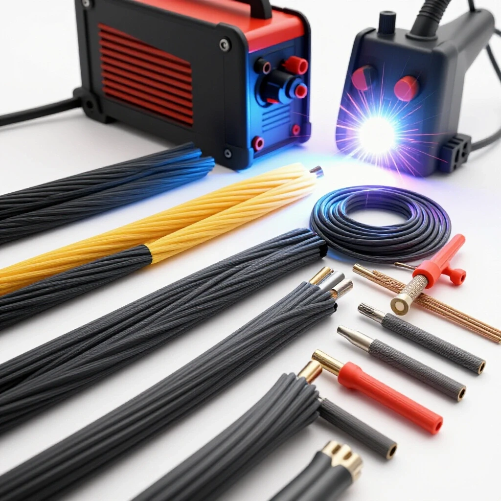
When you are choosing workshop machinery, it is easy to get distracted by digital displays and brand colors. However, the physical construction of your cables determines how much of that rated amperage actually reaches your arc. I remember a project where a friend bought a premium 250-amp MIG welder but complained about a stuttering arc and poor penetration. After a quick teardown of his setup, I found he was using a 50-foot extension lead made of 6-gauge wire. We swapped it for a 2/0 gauge cable, and the machine immediately transformed. Cutting through the marketing hype means looking at the raw materials, specifically the conductor cross-section and the quality of the insulation.
Why Conductor Mass Determines Real-World Welding Performance
Conductor mass refers to the physical volume of copper strands inside your welding lead. This mass determines the electrical resistance of the cable, which dictates how much current can flow without generating excessive heat or causing a significant drop in voltage over a specific distance.
When you look at metal lathe comparison guides, you focus on the rigidity of the bed to prevent vibration. In the world of MIG welding, cable gauge is your electrical rigidity. A thin cable lacks the “stiffness” to deliver a consistent flow of electrons. If the cable is too small for the amperage, it acts like a heater. You lose power to the air as heat instead of using it to melt your wire and base metal. This is why I always check the actual AWG (American Wire Gauge) rating rather than trusting the “heavy-duty” label on the packaging.
I have found that many budget-tier machines come with copper-clad aluminum (CCA) leads. These look like copper but have an aluminum core. Aluminum has higher resistance than pure copper. If you are serious about choosing workshop machinery that lasts, you need to ensure your leads are 100% oxygen-free copper. Copper leads can handle more current in a smaller diameter, which keeps the setup manageable while maintaining a stable arc.
Understanding AWG Ratings and Amperage Capacity
AWG, or American Wire Gauge, is the standard measurement system for the diameter of electrically conducting wires. In welding, the AWG number tells you the thickness of the copper core, where a smaller number represents a thicker wire with a higher capacity for carrying current over long distances.
Choosing the right size is about balancing your machine’s maximum output with the length of the cable. For a standard 140-amp welder used for light repairs, a #4 or #2 AWG cable is usually plenty for a 25-foot run. However, if you move up to a 250-amp machine for structural work, you should be looking at 1/0 or 2/0 leads. I use a simple rule in my shop: always round up. If the chart says a #2 gauge is “just enough” for your amperage, go with #1 or 1/0.
The following table shows the relationship between amperage, distance, and the required AWG size for a 4% voltage drop, which is a standard benchmark for maintaining arc quality.
| Amperage (Amps) | 0-50 Feet | 50-100 Feet | 100-150 Feet | 150-200 Feet |
|---|---|---|---|---|
| 100 | #4 | #2 | #1 | 1/0 |
| 150 | #2 | #1 | 2/0 | 3/0 |
| 200 | #1 | 2/0 | 3/0 | 4/0 |
| 250 | 1/0 | 3/0 | 4/0 | 250 MCM |
| 300 | 2/0 | 4/0 | 250 MCM | 300 MCM |
Evaluating Lead Flexibility and Strand Count
Strand count refers to the number of individual fine copper wires bundled together to form the main conductor. A higher strand count results in a more flexible cable that is easier to coil, maneuver around obstacles, and use for long periods without causing operator fatigue.
In my experience, flexibility is just as important as thickness. If you are working in a tight shop, dragging a stiff, low-strand cable is a nightmare. It feels like wrestling a frozen garden hose. When I evaluate cable quality, I look for “Class K” or “Class M” stranding. Class M has more strands than Class K and is incredibly supple. This flexibility prevents the cable from kinking, which can break internal strands over time and increase electrical resistance.
Think of it like the bearings in a motor. Just as you look for high-quality motor bearings lifetimes when buying a lathe, you want high strand counts for cable longevity. A stiff cable puts unnecessary stress on the welder’s internal connection lugs. Over time, this can lead to loose internal joints and even board failure due to vibration and heat.
- High strand count (Class M): Best for frequent movement and tight spaces.
- Medium strand count (Class K): Standard for most industrial applications.
- Low strand count: Often found in cheap jumper cables; avoid these for welding.
The Impact of Insulation Material on Shop Safety
Insulation is the protective jacket, usually made of EPDM rubber or Neoprene, that surrounds the copper conductor. It must be thick enough to prevent electrical leaks while remaining resistant to high temperatures, oil, grease, and the sharp metal shards common in fabrication environments.
I have seen many “budget” cables with thin plastic jackets that crack after one winter. When you are choosing workshop machinery, you want materials that handle the environment. EPDM (Ethylene Propylene Diene Monomer) is the gold standard for welding jackets. It stays flexible in the cold and doesn’t melt the moment a stray spark hits it. Neoprene is also excellent because it resists oil and chemicals better than standard rubber.
If you are working near a milling machine or a lathe, your cables will inevitably sit in a puddle of cutting fluid or oil. If the jacket isn’t rated for oil resistance, it will swell and eventually peel. This exposes the copper, creating a shock hazard and a fire risk. Always look for a jacket marked with “600V” and a temperature rating of at least 105°C (221°F).
Calculating Voltage Drop and Its Effect on the Arc
Voltage drop is the loss of electrical pressure that occurs as current travels through a conductor. In MIG welding, a significant voltage drop causes the arc to become unstable, leading to excessive spatter, poor bead profile, and a lack of fusion in the base metal.
You might have the best milling machine buying tips in the world, but if your welder’s voltage is dropping by 10% before it hits the gun, your welds will look like popcorn. I use a digital multimeter to test for this. I check the voltage at the machine terminals while welding and then check it at the arc. If there is a gap of more than 1 or 2 volts, the cable is either too thin or too long.
Longer leads are convenient, but they are the primary cause of voltage drop. If you need to weld 100 feet away from your power source, you cannot use the standard 2-gauge wire that came with the machine. You must increase the diameter to compensate for the distance. It is a simple trade-off: more distance requires more copper.
- Measure the total length of the circuit (lead plus ground).
- Determine the maximum amperage you plan to use.
- Consult a voltage drop chart to find the minimum AWG.
- Increase one size if you are at the upper limit of the range.
Assessing Connection Quality and Terminal Lugs
Terminal lugs and connectors are the mechanical points where the cable attaches to the welder and the work clamp. These connections must be tight, clean, and made of high-conductivity materials like brass or copper to ensure a low-resistance path for the current.
I have repaired many machines where the owner thought the transformer was dying, but the real issue was a loose Dinse connector. A loose connection creates a “hot spot.” Heat increases resistance, which creates more heat, eventually melting the connector or damaging the machine’s internal driver board. When choosing workshop machinery, I look at the size of the output studs. A machine with small, flimsy plastic connectors is a red flag.
I prefer heavy-duty brass Dinse-style connectors. They twist and lock into place, providing a large surface area for current transfer. For the work clamp, I throw away the thin steel stamped clamps that come with most hobby welders. I replace them with solid brass “C” style clamps or heavy-duty copper-jawed spring clamps. This ensures the ground is just as solid as the power lead.
Real-World Case Study: The 50-Foot Shop Extension
I recently helped a local shop optimize their setup. They were running a 200-amp MIG welder with 15-foot leads. They needed to reach a large trailer frame 40 feet away, so they bought a 50-foot set of #4 AWG cables. They immediately noticed the wire was “stuttering” and the weld puddle was cold, even with the machine turned all the way up.
We did a side-by-side comparison. First, we measured the voltage at the machine: 24 volts. Then, we measured it at the end of the 50-foot #4 cables: it had dropped to 19.5 volts. That is a 18% loss. We replaced those leads with 1/0 AWG copper cables. The voltage at the arc jumped back up to 23.2 volts. The stuttering stopped, and the penetration was deep and consistent. This proved that even a high-end machine cannot overcome the physics of a thin wire.
Practical Steps for Inspecting New Welding Leads
When you are ready to invest in new cables, do not just trust the label on the box. Use these steps to verify the quality of the leads before you hook them up to your machine.
- Check the Jacket Markings: Look for the AWG size, temperature rating (105°C), and voltage rating (600V) printed directly on the insulation.
- Verify the Material: Cut a small sliver off the end of the wire. If the center of the strands is silver or white, it is aluminum-clad. It should be bright orange-pink copper all the way through.
- Count the Strands: While you don’t have to count every single one, compare the strand thickness to a standard extension cord. Welding lead strands should be much finer, almost like hair.
- Test the Flexibility: Coil the cable in a 12-inch circle. It should lay flat without trying to spring back or kink.
- Inspect the Lugs: Ensure the lugs are crimped with a hydraulic press or soldered properly. A loose crimp will fail under high heat.
Summary of Cable Selection Benchmarks
To make a confident choice, you need objective benchmarks. Use these figures as a guide when you are comparing different cable options for your workshop.
- Maximum Allowable Voltage Drop: 4% of the total output voltage.
- Ideal Temperature Rating: 105°C (221°F) for industrial use.
- Copper Purity: 99.9% oxygen-free copper.
- Strand Class: Class K (standard) or Class M (high-flex).
- Connector Type: Dinse 35-70 or larger for machines over 200 amps.
Choosing the right cable gauge is about ensuring your machine can perform at its engineered limit. Just as you wouldn’t put thin tires on a heavy-duty truck, you shouldn’t put thin cables on a powerful MIG welder. By focusing on conductor mass, insulation quality, and connection integrity, you can cut through the marketing hype and build a setup that delivers consistent, high-quality welds every time you pull the trigger.
FAQ
Does cable gauge affect the duty cycle of my MIG welder? Yes, indirectly. If your cables are undersized, they will heat up. This heat can transfer back into the machine’s internal components, potentially causing the thermal overload protection to trip sooner than expected. Using the correct gauge ensures the machine operates within its designed temperature range.
Can I use a thicker cable than what is recommended? Absolutely. There is no electrical downside to using a thicker cable, other than the increased weight and cost. A thicker cable will have less resistance and less voltage drop, which generally improves arc stability. Many professionals “up-size” their cables by one gauge to ensure maximum performance.
What is the difference between #2 and 2/0 cable? In the AWG system, #2 is a smaller diameter wire, often used for 100-150 amp applications. 2/0 (pronounced “two-ought”) is much thicker and is designed for high-amperage industrial welding, typically 250-300 amps or long-distance runs.
Is copper-clad aluminum (CCA) okay for a home workshop? I generally advise against it. While it is cheaper and lighter, it has much higher resistance. If you use CCA, you must use a much larger gauge to get the same performance as a smaller copper wire. In the long run, pure copper is a better investment for arc consistency.
How do I know if my current cables are too thin? Feel the cables after a few minutes of continuous welding. If they are uncomfortably hot to the touch, they are undersized for the amperage you are using. You might also notice the arc sounding “weak” or the wire stubbing into the metal despite high settings.
Does the ground cable need to be the same gauge as the torch lead? Yes. The welding current travels in a complete loop. The ground cable carries the exact same amount of current as the electrode lead. If your ground is thinner, it creates a bottleneck for the entire system, leading to the same power losses as a thin power lead.
How does cable length affect my welder’s settings? As cables get longer, the voltage drop increases. This means you might have to turn your voltage dial higher on the machine to get the same results at the torch. Using the correct, thicker gauge for long runs minimizes this need for adjustment.
What is the best way to store heavy-gauge welding cables? Avoid tight coils or hanging them over sharp hooks. Large, loose loops are best. This prevents the internal copper strands from stretching or breaking and keeps the insulation from cracking over time.
Can I mix different gauges of cable in one setup? You can, but the thinnest cable in the circuit will be your bottleneck. The entire circuit’s capacity is limited by its weakest link. If you have a 50-foot run of 2/0 and a 5-foot “whip” of #2, the #2 section will still generate heat and resistance.
Why are some cables more expensive if the AWG is the same? The price difference usually comes down to the jacket material and the strand count. A cable with a high-flex Class M rating and a Neoprene jacket costs more than a stiff Class K cable with a basic rubber jacket. The extra cost pays for better usability and durability.
Should I solder or crimp my cable lugs? A high-pressure hydraulic crimp is the industrial standard. It creates a “cold weld” between the copper and the lug. Soldering is acceptable for home use, but if the cable gets extremely hot, the solder can soften. A good crimp is more reliable under heavy loads.
Is it worth upgrading the factory cables on a new welder? Often, yes. Manufacturers of budget and mid-tier machines frequently save money by providing the thinnest cables possible for the machine’s rating. Upgrading to a larger, more flexible copper cable is one of the most effective ways to improve the “feel” and performance of a new welder.
(This article was written by one of our staff writers, Steven Brooks. Visit our Meet the Team page to learn more about the author and their expertise.)