How to Test the Strength of Custom Structural Welds (Guide)
I remember standing over a custom-built motor mount for a 50-horsepower drive system about ten years ago. On paper, the welds looked clean, but every time the motor ramped up to full RPM, a violent vibration traveled through the entire frame. I spent two days checking the spindle alignment and the motor controller settings, thinking it was an electrical or mechanical balancing issue. It wasn’t until I took a closer look at the structural joints that I realized the problem. The welds had “cold lap,” meaning the metal looked like it was fused but was actually just sitting on the surface. That experience taught me that if you cannot verify the integrity of your connections, your entire machine is built on a foundation of sand.
In my 15 years as a diagnostic specialist, I’ve learned that troubleshooting a failed fabrication often starts long before the machine is powered on. Whether you are dealing with tool chatter on a lathe or a structural frame that keeps warping, the root cause is frequently found in the quality of the metal fusion. We often get caught up in the “black box” of electrical gremlins or complex software errors, but if the physical joints are weak, the machine will never reach its specified tolerances.
Building a Diagnostic Foundation for Metal Joint Reliability
Establishing a diagnostic framework means moving away from “it looks okay” to a systematic verification of how well your metal parts are actually bonded. This process involves isolating variables like heat input, travel speed, and material preparation to ensure that the final assembly can handle the stresses of a working shop environment.
Before we get into the physical tests, we have to talk about the baseline. When a machine vibrates or a bracket fails, I always look at the fabrication history. Was the steel cleaned of mill scale? Was the shielding gas flow set correctly? In a diagnostic setting, we treat the weld like a mechanical component. If a bolt has a torque spec, a weld has a penetration requirement. If you ignore these, you are just guessing.
Visual Assessment: Spotting Surface Defects Before They Fail
Visual inspection is the process of using your eyes and basic measuring tools to identify surface-level flaws that indicate deeper structural weaknesses. It is the fastest way to catch issues like porosity, undercut, or lack of fusion before they cause a catastrophic failure in your equipment.
I always start with a high-intensity flashlight and a magnifying glass. You are looking for specific indicators that the metal didn’t flow correctly. For example, porosity—which looks like tiny pinholes or a sponge-like texture—is a common diagnostic sign of contaminated shielding gas or wind blowing your gas away. If you see this on a structural joint, you don’t even need to test further; you already know the internal structure is compromised.
- Undercutting: This is a groove melted into the base metal right at the edge of the weld. If it’s deeper than 0.030 inches, it acts like a “perforation” on a piece of paper, giving the metal a perfect place to snap under stress.
- Overlap (Cold Lap): This happens when the weld metal rolls over the base metal without actually fusing. It looks like a “bead” sitting on top rather than being part of the plate.
- Crater Cracks: Small cracks at the end of a weld bead. These are notorious for “zippering” open when the machine undergoes thermal expansion or vibration.
Destructive Testing: Breaking Samples to Prove Fusion
Destructive testing involves intentionally breaking a replica of your joint to see how it failed internally. By examining the “fracture surface,” you can determine if your machine settings—like voltage and wire feed speed—are producing the deep penetration needed for structural stability.
In my shop, I never trust a new setup until I’ve performed a “fillet break test.” I’ll weld a T-joint on scrap material of the same thickness as my project. Then, I’ll put it in a heavy vise and hit it with a sledgehammer until it folds over. If the weld snaps and I see shiny, un-fused base metal at the root, I know my penetration is shallow. Ideally, the metal should tear through the center of the weld or the base metal itself, showing that the bond was stronger than the surrounding material.
Table 1: Shop-Floor Weld Defect Diagnosis
| Symptom | Probable Root Cause | Diagnostic Fix |
|---|---|---|
| Tiny pinholes (Porosity) | Gas flow too low or wind | Increase flow to 20-25 CFH; use a screen. |
| Weld snaps easily in vise | Lack of root penetration | Increase Amperage/Voltage; slow down travel. |
| Deep groove at weld edge | Excessive heat or wrong angle | Adjust torch angle; decrease voltage. |
| Brittle, glass-like beads | Wrong filler metal for alloy | Match filler to base metal (e.g., ER70S-6). |
The Shop-Floor Bend Test for Ductility
A bend test is a diagnostic procedure where a strip of welded metal is forced into a “U” shape to check for cracks. This tells you if the joint is brittle or if there are hidden inclusions, like slag or gas pockets, that will cause the joint to fail under a load.
I remember a project where we were building a custom hydraulic press frame. The welds looked beautiful, but the bend test revealed “lamellar tearing.” The heat was so high it was pulling the layers of the steel apart. To do this yourself, cut a 1-inch wide strip of your test weld, grind the “face” (top) and “root” (bottom) flush, and bend it 180 degrees over a mandrel. If it opens up more than 1/8th of an inch, your process is flawed.
- Cut a test specimen approximately 6 inches long.
- Grind the weld reinforcement flat so the strip is a uniform thickness.
- Use a hydraulic shop press or a heavy vise to bend the piece.
- Inspect the “radius” (the outside of the bend) for any tearing.
Using Shop Loads to Validate Structural Performance
Load testing is the application of controlled weight or pressure to a finished assembly to ensure it can handle its intended operational stress. This is a critical step for fabricators building engine hoists, shelving, or machine stands where a failure could result in damaged equipment.
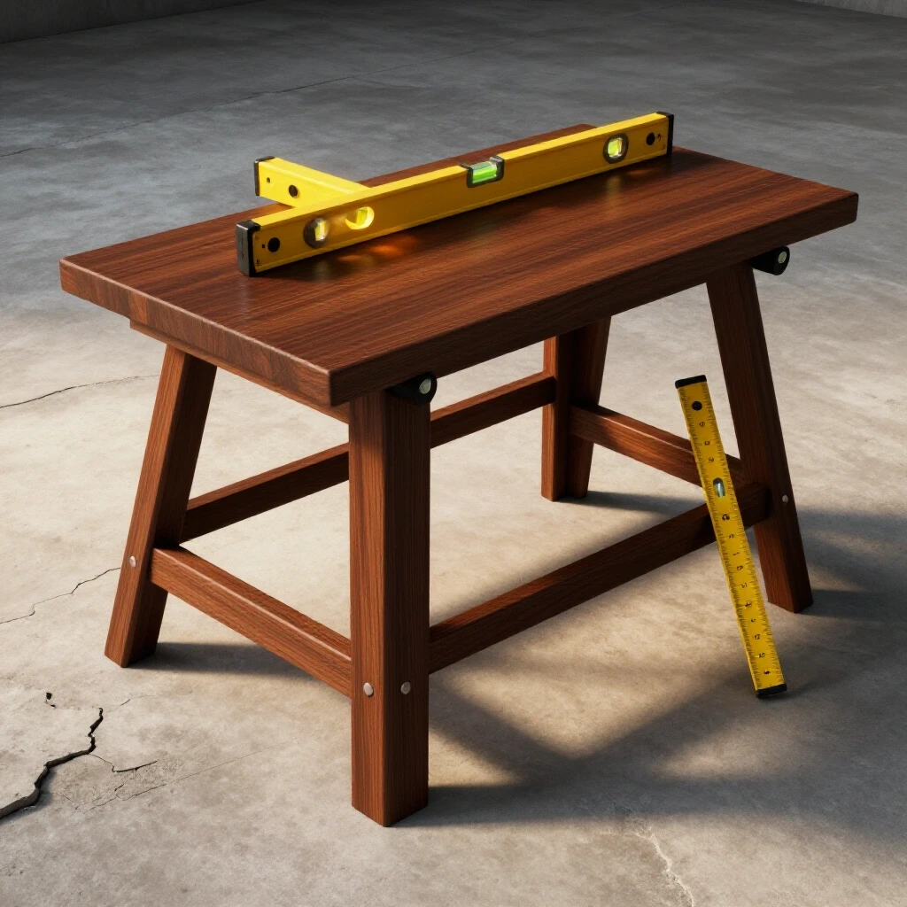
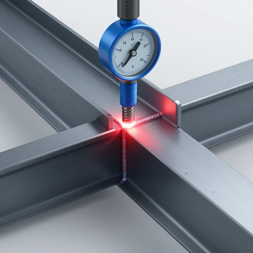
When I’m troubleshooting a machine stand that feels “spongy,” I’ll use a dial indicator to measure deflection. I’ll place the indicator under a structural beam and then apply a known load—like a heavy crate or a piece of machinery. If the beam deflects more than 0.005 to 0.010 inches over a short span, the joints might be flexing, or the material itself is undersized.
- Static Load: Hanging a weight that is 1.5 times the expected working load.
- Dynamic Load: Moving the load or vibrating the frame to see if any welds “ping” or show signs of stress.
- Deflection Tracking: Using a digital dial indicator to ensure the frame returns to “zero” after the load is removed.
Troubleshooting Mechanical and Metallurgical Defects
Identifying why a joint failed requires looking at the metallurgy and the mechanics of the welding process. Often, a “bad weld” is actually a symptom of a machine error, such as an inconsistent wire feeder or a fluctuating power supply that causes “arc hunting.”
I once worked on a CNC plasma table where the gantry kept losing steps. Everyone thought it was the stepper motors. It turned out the welded gantry frame had warped during fabrication. The internal stresses in the welds were so high that the frame was physically twisting as it warmed up. By diagnosing the “residual stress” in the joints, we were able to heat-treat the frame and stop the binding.
Table 2: Mechanical vs. Metallurgical Issues
| Issue | Observation | Diagnostic Tool |
|---|---|---|
| Tool Chatter | Vibration at specific RPMs | Smartphone Vibration Analyzer |
| Structural Warping | Frame pulls out of square | Precision Square / Feeler Gauges |
| Cold Cracking | Cracks appear 24 hours later | Dye Penetrant Kit |
| Spindle Backlash | Movement in the headstock | Dial Indicator (0.001″ res) |
Isolating Root Causes of Joint Failure
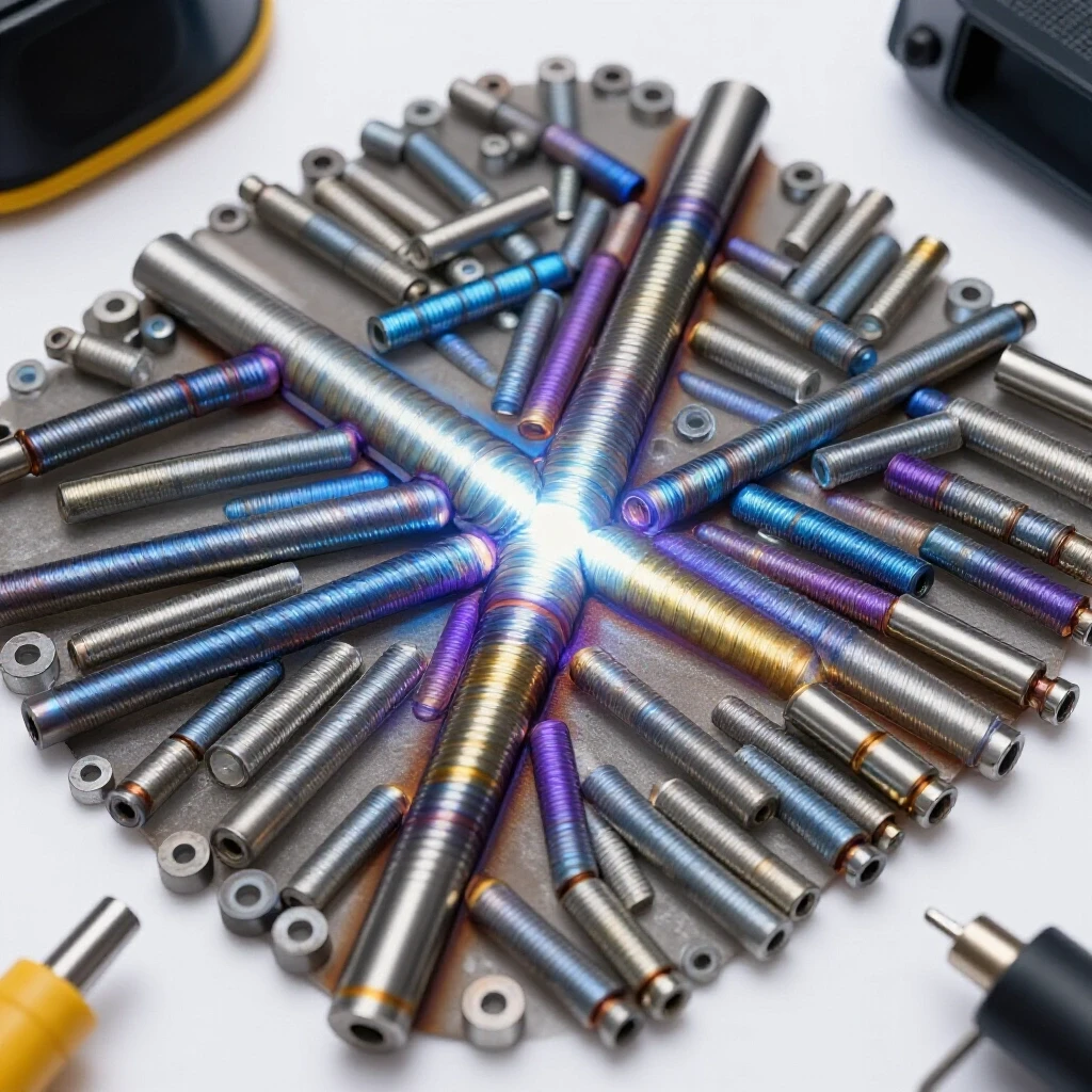
To truly master workshop diagnostics, you have to look at the “Heat Affected Zone” (HAZ). This is the area of base metal right next to the weld that didn’t melt but got hot enough to change its properties. If you see a blue or purple tint extending far away from the joint, you’ve put too much heat into the part, which often makes the steel soft or brittle.
In my experience, “tool chatter” is frequently caused by a lack of rigidity in these zones. If a lathe stand is made of thin-walled tubing with over-heated welds, the metal loses its “stiffness.” You can test this by tapping the structure with a dead-blow hammer. A solid, well-fused structure will have a high-pitched “ring,” while a failed or poorly fused one will have a dull “thud.” This is an old-school trick, but it works surprisingly well for isolating loose components in a complex assembly.
Actionable Tracking Framework for Fabricators
When you are deep in a diagnostic puzzle, it is easy to lose track of what you’ve tested. I recommend keeping a simple logbook for your structural projects. This isn’t about paperwork; it’s about not repeating your mistakes.
- Material Prep Log: Did you grind to shiny metal? (Yes/No)
- Machine Settings: What was the Voltage and Wire Speed?
- Gas Verification: Did you check for leaks in the regulator?
- Test Sample Results: Did the bend test pass?
- Post-Weld Inspection: Any signs of undercut or porosity?
By following this checklist, you remove the “magic” from the process. If a weld fails, you look at the log. If the voltage was too low for the plate thickness, you have your answer. No more guessing, no more frustration.
Key Takeaways for Shop Diagnostics
Mastering the reliability of your builds is about observation and iteration. Start with a visual check, move to a physical break test on a sample, and finally, validate the assembly with a load test. If you find a defect, don’t just “weld over it.” Grind it out, find the root cause (like a dirty ground clamp or a drafty shop), and fix the process. This systematic approach is what separates a hobbyist from a specialist who can trust their machines to perform day after day.
Frequently Asked Questions
How can I tell if a weld has deep penetration without cutting it? While you can’t see inside the metal, you can look for “heat tint” on the back side of the plate. If you are welding 1/4-inch steel and the back side doesn’t show a discolored “ghost” of the weld bead, you likely aren’t getting deep enough. For critical joints, always run a test piece of the same thickness and break it in a vise to verify your settings.
Why does my weld look like a sponge with tiny holes? This is porosity, usually caused by a loss of shielding gas. Check your regulator for freezing, look for holes in your gas hose, or see if a fan or open door is blowing the gas away from the arc. It can also be caused by welding over rust, oil, or mill scale.
What is the “hammer test” and is it actually useful? The hammer test is a basic way to check for “fusion.” By hitting a T-joint sample with a sledgehammer, you force the joint to flex. If the weld peels off the plate like a sticker, you have “cold lap” or lack of fusion. If the metal bends or the weld tears down the middle, the bond to the base metal is strong.
Can tool chatter be caused by a bad weld on a machine stand? Absolutely. If a joint in your machine stand isn’t rigid, it can create a “harmonic frequency” that vibrates when the motor hits a certain RPM. This vibration travels into the workpiece, causing chatter. Strengthening the joints or adding gussets can often dampen these vibrations.
How do I fix “undercut” in my structural joints? Undercut is usually caused by holding the arc too long at the edges or using too much voltage. To fix it, lower your voltage slightly or change your torch angle so you are “pushing” more metal into the edges of the joint. You can also try a slightly faster travel speed.
What should I do if I find a crack in a finished weld? Never just weld over a crack. The crack will likely continue to grow underneath the new bead. You must grind out the entire crack until you reach solid metal, then re-clean the area and weld it again using the correct heat settings.
How much deflection is normal for a custom metal workbench? For a heavy-duty workbench, you generally want to see less than 1/360th of the span. For example, on a 5-foot (60-inch) table, the center shouldn’t sag more than about 0.16 inches under a full load. If it sags more, your structural joints or the beams themselves are too weak.
Does the color of the weld tell me anything about its strength? On stainless steel, a straw or gold color is good, while a dark purple or grey color means you used too much heat, which can reduce corrosion resistance. On mild steel, color is less of an indicator than the shape of the bead and the lack of surface defects like porosity.
Why did my weld snap when the temperature dropped in my shop? This is often “hydrogen embrittlement” or “cold cracking.” If the metal is very cold, it acts as a heat sink, chilling the weld too fast and making it brittle. In cold shops, it is a good idea to pre-heat the steel to about 100-150 degrees Fahrenheit with a torch before welding.
What is the best tool for checking the squareness of a large frame? For large fabrications, a 3-4-5 triangle method using a tape measure is very accurate. For smaller frames, a precision machinist’s square or a digital protractor is best. Always check for “twist” by looking across the top of the frame with “winding sticks” or a laser level.
(This article was written by one of our staff writers, Paul Whitaker. Visit our Meet the Team page to learn more about the author and their expertise.)