How to Use Spaghetti Diagrams to Reduce Workshop Steps (Fix)
I remember the exact moment I realized my shop was working against me. I was finishing a custom gate project in my 480-square-foot garage, and by 3:00 PM, my lower back was screaming. I wasn’t tired from welding or grinding; I was exhausted from walking. I spent the next hour retracing my steps and realized I had crossed the floor from the welder to the chop saw nearly fifty times. In a space that small, that much movement is a sign of a broken system.
As we scale our operations from basic hobby setups to professional-grade fabrication hubs, we often focus on the “big” upgrades. We buy the CNC plasma table, the heavy-duty ironworker, or the 3-phase rotary converter. However, we often drop these powerful tools into the same old layout, creating a tangled mess of movement. This guide focuses on using manual path-mapping techniques to visualize those inefficiencies. By drawing out your actual footsteps on paper, you can identify where your layout is stealing your time and energy.

The Physics of Small-Shop Material Handling
Material handling is the silent killer of productivity in any shop under 500 square feet. It involves every moment you spend moving a raw steel tube from the rack to the saw, or shifting a heavy plate onto the CNC bed. In a compact space, every foot of travel counts toward your daily fatigue and your project’s bottom line.
When I first started, I put my steel rack in the far corner because it was “out of the way.” This meant every time I needed a piece of stock, I had to shimmy past my welding table and navigate around my air compressor. By the time I got the material to the saw, I had already wasted two minutes. In a professional workflow, we want “linear flow.” This means the material enters one side of the shop, moves through the processing stations in a logical order, and exits as a finished product without ever doubling back.
Identifying High-Traffic Zones in a 500-Square-Foot Space
High-traffic zones are the areas where you spend 80% of your time, usually centered around your primary workbench, the welder, and the tool chest. In a small fabrication shop, these zones often overlap, creating “choke points” where you find yourself constantly moving one tool to reach another.
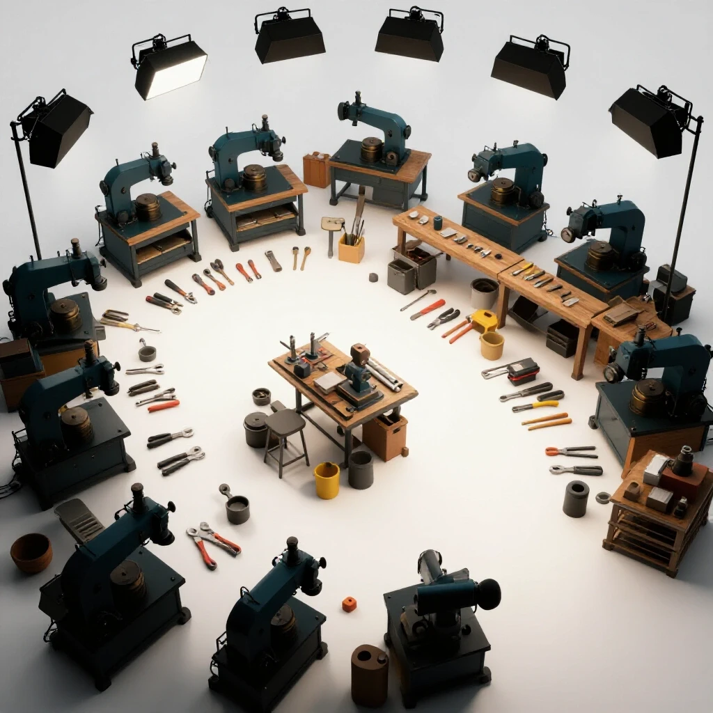
To identify these zones, you don’t need sensors or fancy tech. You need a piece of graph paper and a few colored markers. I call this “visualizing the tangle.” When you map out your movements, you’ll likely see a dense knot of lines around your main table. The goal is to spread those lines out or align them so that the “tangle” becomes a series of smooth, sweeping curves. If you find yourself spinning in circles in a three-foot radius, your most-used tools are likely too far apart.
Powering the Evolution: 3-Phase Solutions and Layout Constraints
As you integrate professional machinery like a CNC plasma or a heavy-duty mill, you’ll likely encounter the 3-phase power hurdle. Most residential shops only have single-phase 240V power, which won’t run industrial motors efficiently. Integrating a phase converter isn’t just an electrical task; it’s a layout challenge because these units can be noisy and require specific ventilation.
I learned this the hard way when I installed my first 10HP rotary phase converter. I tucked it under a bench to save space, but the heat it generated started tripping the thermal overload. I had to move it, which meant rerunning my conduit and changing my walking path. When planning your layout, the “power center” must be accessible for maintenance but placed where its footprint doesn’t interrupt the flow of material from the saw to the welding station.
Rotary Phase Converters vs. Static Converters for CNC Workflows
A rotary phase converter (RPC) uses a literal idler motor to create a third leg of power, providing a “true” 3-phase signal that is essential for the sensitive electronics in CNC systems. Static converters are cheaper but only “start” the motor, often resulting in a 30% loss of horsepower, which can lead to stalls during heavy cuts.
For a scaling shop, the RPC is usually the better investment, but it requires a dedicated “home” in your floor plan. You need to account for the physical space of the unit and the “swing room” for the heavy-gauge wire. If you place the RPC in a location that requires you to walk around it every time you go to the tool chest, you’ve traded electrical efficiency for physical inefficiency.
- Rotary Phase Converter: Best for CNC and high-torque motors; provides 100% power.
- Static Converter: Good for simple drill presses; significant power loss.
- Variable Frequency Drive (VFD): Excellent for single-tool speed control; requires individual wiring for each machine.
Designing High-Volume Air Management for Compact Spaces
Air quality management is often an afterthought until the shop is filled with plasma smoke or grinding dust. In a 500-square-foot space, a single CNC plasma cut can make the air unbreathable in minutes. Designing a high-volume filtration system requires understanding CFM (Cubic Feet per Minute) and how ducting affects the physical “lanes” you walk in.
I used to run a portable “smoke eater” that I dragged around the shop. It was a tripping hazard and always seemed to be in the way of my welding lead. When I switched to a fixed ducting system with a wall-mounted cyclone collector, I regained four square feet of floor space. That might not sound like much, but in a small shop, four square feet is the difference between a clear path and a bottleneck.
Calculating Duct Static Pressure and Optimal Vent Placement
Static pressure is the resistance your air collector faces as it tries to pull air through the pipes. Every 90-degree bend and every foot of hose increases this resistance, which lowers your actual CFM at the tool. To keep the air clean without cluttering your floor, you want to run your main trunk line along the ceiling or high on the walls.
When you map your workflow, look for where the “dirty” work happens—usually the grinding station and the plasma table. Place your intake vents as close to these sources as possible. If you have to pull a 10-foot flexible hose across the floor to reach your grinder, you’re creating a physical barrier that will show up as a “detour” on your path-mapping diagram.
- Minimum Airflow for Grinding: 500–800 CFM.
- Minimum Airflow for CNC Plasma: 1,000–1,500 CFM (depending on table size).
- Ducting Rule: Use smooth-walled pipe and keep bends to a minimum to reduce static pressure loss.
| Tool Type | Recommended CFM | Duct Diameter | Max Hose Length |
|---|---|---|---|
| Bench Grinder | 350 | 3″ | 6 ft |
| CNC Plasma (Small) | 1,200 | 6″ | 10 ft |
| Vertical Band Saw | 400 | 4″ | 8 ft |
| Welding Station | 600 | 5″ | 12 ft |
Executing the Path-Mapping Exercise with Paper and Tape
Visualizing your movement is the most effective way to “fix” a broken shop layout. By drawing a line for every trip you take during a standard task, you create a “spaghetti-like” image that reveals redundant steps. This isn’t about fancy software; it’s about seeing the physical reality of your workday on a piece of paper.
I recommend doing this for a “representative” project—something you build often. For me, it was a simple bracket set. I took a clipboard, a floor plan of my shop, and a red pen. Every time I moved from the welder to the drill press, I drew a line. By the end of the hour, the paper was a mess of red ink. The densest areas of ink showed me exactly where I was wasting my life.
Step-by-Step Guide to Visualizing Your Daily Footsteps
To start, you need an accurate bird’s-eye view of your shop. Measure your walls and your large machinery, then sketch them on graph paper at a scale of 1/4 inch per foot. Don’t forget to include fixed obstacles like support columns, water heaters, or electrical panels.
- Prepare the Map: Make ten copies of your blank shop layout. You’ll want a fresh sheet for different tasks (e.g., one for “cutting day,” one for “assembly day”).
- The Tracking Phase: As you work, keep the clipboard nearby. Every time you walk from Point A to Point B, draw a line. Don’t worry about being neat; the goal is to see the volume of movement.
- Analyze the “Tangles”: Look for lines that cross the same area repeatedly. If you see twenty lines between your workbench and your welder, but they are ten feet apart, you are walking 200 feet for no reason.
- The Tape Method: Once you have a new layout idea based on the drawing, use painter’s tape on the actual shop floor to mark the “new” positions of your tools. Walk the paths before you actually bolt anything down.
Integrating CNC Machinery into an Optimized Workflow
Adding a CNC plasma table or a milling machine is a turning point for any fabrication shop. It moves you from “manual labor” to “process management.” However, these machines have a “gravity” that pulls everything else toward them. They require a computer station, a water table or downdraft system, and space to load heavy sheets of metal.
When I integrated my 4×4 plasma table, I initially put it in the center of the shop because I wanted access to all four sides. I quickly realized that this created a permanent “island” that I had to navigate around for every other task. I eventually moved it against a wall with a “loading zone” cleared out in front of it. This opened up a long, straight path through the center of the shop, reducing my daily steps by nearly 15%.
Software and Tooling Files: The Digital Path to Physical Efficiency
Efficiency isn’t just about moving your feet; it’s about moving your mind. If your computer station is in the house but your CNC is in the garage, you’re going to walk a mile just troubleshooting a single cut file. Your CAD/CAM station should be integrated into the shop environment, protected by a “clean zone” or a dust-proof cabinet.
I set up a small, wall-mounted desk right next to the CNC controller. This allowed me to tweak my G-code or adjust a lead-in without leaving the machine. By keeping the “digital work” and the “physical work” in the same zone, I eliminated the back-and-forth travel that usually happens when a cut goes wrong. This “localized” workflow is a key part of reducing the lines on your path-mapping diagram.
- CAD (Computer-Aided Design): Where you draw the part.
- CAM (Computer-Aided Manufacturing): Where you turn the drawing into toolpaths (G-code).
- Controller: The hardware that tells the motors where to move.
- Pro Tip: Use a wireless keyboard and mouse with a protective silicone cover to prevent metal dust from ruining the electronics.
Managing Floor Load and Machinery Leveling
As your shop matures, your equipment gets heavier. A cast-iron welding table or a CNC table with a full water tray can weigh upwards of 1,500 pounds. Most residential garage floors are 4 inches thick, which is generally sufficient for 3,000–4,000 PSI, but concentrated loads can cause cracking over time.
When I moved my heavy equipment, I made sure to use leveling feet that distribute the weight over a larger surface area. A machine that isn’t level won’t just cut poorly; it will be harder to move if you need to adjust your layout later. I keep a high-quality machinist’s level in my toolbox specifically for this. If a machine is “rocking” even slightly, it will vibrate during operation, leading to premature wear on your 3-phase motors and CNC lead screws.
- Floor Load Tip: If you’re installing a very heavy machine, consider a “spreader plate” of 1/2-inch steel under the feet to distribute the weight.
- Leveling: Check your CNC table for level every six months; concrete floors can settle, especially in newer builds.
Workflow Optimization Checklist
Before you start moving heavy machinery, go through this checklist. It’s much easier to move a drawing on paper than a 600-pound ironworker on the floor.
- Material Entry: Is there a clear path from the door to the material rack?
- The “Golden Triangle”: Are your primary workbench, welder, and main tool chest within three steps of each other?
- Obstacle Removal: Are there any “permanent” items (trash cans, scrap bins) blocking your most common walking paths?
- Power Access: Can you reach your 3-phase converter or main breaker without moving a project out of the way?
- Air Quality: Is the dust collector intake within 6 feet of your primary grinding area?
- Lighting: Do you have at least 50 foot-candles of light at every “stop” on your path-mapping diagram?
Measuring Success: Before and After Metrics
The only way to know if your layout changes worked is to measure the difference. After I reorganized my shop based on my path-mapping exercise, I tracked the time it took to build my standard bracket set. I went from 45 minutes down to 32 minutes. That 13-minute saving, multiplied over a month, gave me back nearly ten hours of “free” time.
You can also measure “foot-feet.” If your diagram showed you walking 500 feet for a project and the new layout shows 200 feet, you’ve reduced your physical wear and tear by 60%. In a solo shop, you are the most valuable piece of equipment. Reducing your “mileage” is the best way to ensure you can keep fabricating for the next twenty years.
Conclusion
Transitioning a shop from a hobby space to a professional-grade facility isn’t about how much money you spend on tools. It’s about how those tools interact with each other and with you. By using the path-mapping method, you can see the invisible “waste” in your day. You can identify the redundant steps, the dangerous “detours,” and the bottlenecks that keep you from finishing projects on time.
Start small. Grab a piece of graph paper and track your movements tomorrow. Don’t judge what you see—just record it. Once you see the “spaghetti” of lines on the paper, you’ll have the data you need to make smart, strategic changes to your layout. A more efficient shop isn’t just more productive; it’s a more enjoyable place to work.
FAQ
What is the best way to track my movement if I work alone? The simplest way is the “clipboard and pen” method. Every time you move between two stations, draw a line on a printed floor plan. You don’t need to be precise; the density of the lines will naturally show you where the bottlenecks are.
How much space do I really need around a CNC plasma table? Ideally, you want at least 3 feet of clearance on at least three sides. This allows you to load material, clean the water tray, and maintain the gantry without feeling cramped. If space is tight, prioritize access to the side where you load the most material.
Can I run a CNC machine on a static phase converter? It is not recommended. CNC electronics and motors require stable, balanced voltage. A static converter often results in “unbalanced” legs of power, which can cause the CNC controller to crash or the motors to overheat. A rotary phase converter or a dedicated VFD is a much safer bet.
What is “static pressure” in a dust collection system? Think of it like trying to breathe through a straw. The longer and more “bendy” the straw, the harder it is to pull air. In your shop, every elbow, reducer, and foot of corrugated hose increases static pressure, which reduces the effective suction at your tool.
How do I know if my garage floor can handle a heavy machine? Most standard 4-inch garage slabs can handle up to 40 PSI of “dead load.” If you have a machine that weighs 2,000 pounds and has four 2-inch feet, that’s a lot of pressure on a small area. Using steel spreader plates or larger leveling feet can help distribute that weight.
Why shouldn’t I just put all my tools against the walls? While it seems like it opens up the floor, it often forces you to walk long distances between tools. A “center island” workbench can actually be more efficient because it allows you to rotate between tools with just a step or two, provided it doesn’t block your main material flow.
What is the “Golden Triangle” in a workshop? Adapted from kitchen design, it’s the idea that your three most used stations (e.g., workbench, welder, and tool chest) should form a triangle with sides between 4 and 8 feet long. This minimizes walking while still giving you enough room to work safely.
How often should I redo my path-mapping diagram? Do it every time you add a major piece of equipment or if you notice you’re feeling more tired than usual at the end of the day. Your shop is a living organism; as your projects change, your layout should too.
Is 3-phase power really worth the cost for a home shop? If you plan on running industrial-grade equipment, yes. 3-phase motors are more efficient, last longer, and provide more consistent torque than single-phase motors. The cost of a rotary converter is usually offset by the lower price of used 3-phase industrial machinery.
How can I reduce the noise of a rotary phase converter? Mounting the unit on vibration-damping rubber pads and placing it in a ventilated, sound-insulated cabinet can significantly reduce the “hum.” Just ensure there is plenty of airflow to prevent the motor from overheating.
(This article was written by one of our staff writers, Edward Sinclair. Visit our Meet the Team page to learn more about the author and their expertise.)