Preventing Condensation Inside Compressor Tanks (DIY Guide)
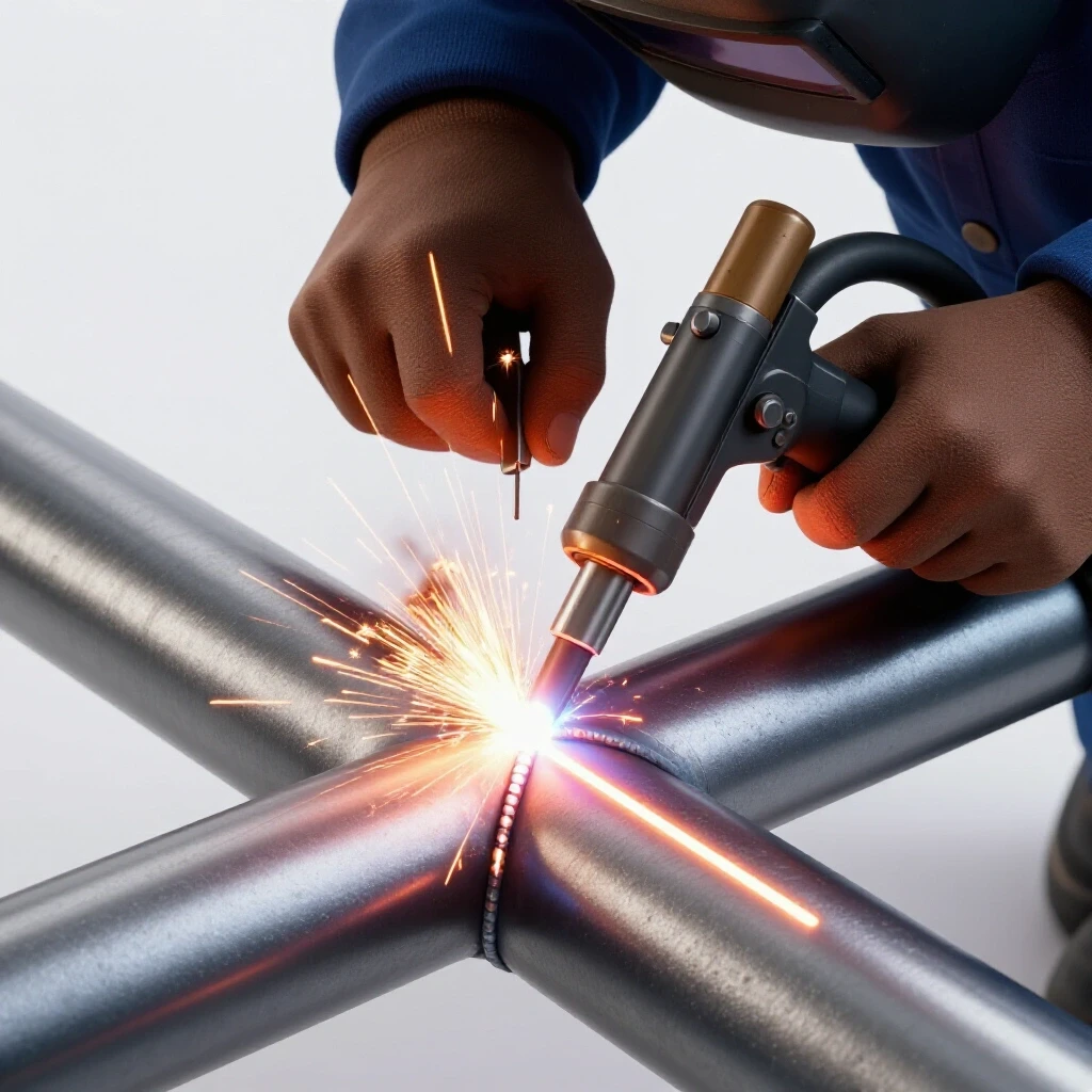
I remember a Tuesday morning three years ago when a simple production run of aluminum TIG welds turned into a nightmare. Every bead I laid looked like a sponge, riddled with the kind of pinhole porosity that makes a fabricator want to throw their torch across the shop. I checked my gas flow, swapped the tungsten, and even opened a fresh pack of filler rod, but the issue remained. It wasn’t until I purged the air line leading to my pneumatic clamps that I saw the culprit: a literal stream of rusty water spraying onto the workbench.
That water didn’t just appear out of nowhere; it was the result of a thermal process happening inside my air storage system. When we compress ambient air, we are also compressing the humidity trapped within it. As that hot, pressurized air cools against the steel walls of a tank, it reaches its dew point and transforms into liquid. For those of us working with precision tools and high-quality welds, this liquid is more than a nuisance. It is a source of tool chatter, internal corrosion, and catastrophic weld defects.
Over my 15 years as a diagnostic specialist, I have learned that “wet air” is often the hidden variable behind erratic machine behavior. If your plasma cutter is consuming nozzles at an alarming rate or your air-powered grinders are vibrating with a strange, heavy resonance, you likely have a moisture problem. Mastering the environment inside your air reservoir is a fundamental skill for any fabricator who values precision and equipment longevity.
Understanding the Physics of Liquid Accumulation in Pressure Vessels
Liquid accumulation in air systems occurs when the temperature of compressed air drops below the point where it can no longer hold water vapor. This transition, known as the dew point, causes water to bead up on the interior surfaces of the tank and eventually pool at the bottom.
When you pull air into a compressor, you are taking a large volume of “wet” atmospheric air and squeezing it into a small space. This process generates significant heat, which allows the air to hold onto that moisture temporarily. However, as soon as that air enters the storage tank, it begins to lose heat to the surrounding environment. As the tank walls cool the air, the water vapor turns back into liquid. If this liquid isn’t managed, it mixes with compressor oil and scale to create an acidic sludge that eats away at your tank from the inside out.
The Relationship Between Pressure, Temperature, and Humidity
The amount of water your system produces is directly tied to the ambient temperature and the relative humidity of your workspace. On a humid 85-degree day, a standard 5-horsepower compressor running at a high duty cycle can produce several gallons of water in a single shift. This isn’t a sign of a broken machine; it is simple thermodynamics at work.
In a fabrication setting, this moisture travels down the line and interferes with the laminar flow of shielding gases or the consistent RPM of air-driven spindles. When water hits a high-speed turbine in a hand tool, it creates a “slug” of mass that causes momentary deceleration. This leads to tool chatter, which ruins surface finishes and accelerates bearing wear. Understanding this cycle is the first step toward isolating the root cause of your equipment’s performance issues.
Diagnostic Pathways for Moisture-Related Fabrication Failures
Identifying moisture as the root cause of a fabrication error requires a systematic approach to eliminate other variables like mechanical wear or electrical interference. We often mistake moisture-induced tool chatter for a loose spindle or a dull end mill, but the fix is entirely different.
If you are experiencing inconsistent arc stability while welding or “spitting” from your pneumatic tools, you need to map out the symptoms. Moisture-related issues are usually intermittent and tend to worsen as the shop warms up or as the compressor runs longer. By tracking these failures against your compressor’s run time, you can confirm if the air quality is the primary driver of the defect.
Comparison of Air Quality to Common Workpiece Defects
| Symptom | Potential Mechanical Cause | Moisture-Related Root Cause |
|---|---|---|
| Weld Porosity | Shielding gas leak or wind | Water vapor in the lines contaminating the weld puddle. |
| Tool Chatter | Worn bearings or loose collet | Liquid “slugs” causing erratic RPM in air motors. |
| Jagged Plasma Cuts | Incorrect travel speed | Water droplets disrupting the ionized plasma arc. |
| Internal Tool Rust | Lack of lubrication | Acidic condensation stripping oil and oxidizing steel. |
| Pressure Drops | Clogged filters or undersized lines | Liquid pooling in “low spots” of the hard piping. |
Building on this, I always recommend a “white cloth test.” Hold a clean white rag a few inches away from an air nozzle and blow air through it for 30 seconds. If the cloth shows dampness or brown spots, your diagnostic path is clear. You aren’t dealing with a mechanical alignment fault; you are dealing with a saturated reservoir.
Manual and Automated Drainage Solutions for Steel Reservoirs
The most effective way to protect a pressure vessel from internal corrosion is to ensure that liquid is removed as quickly as it forms. This requires a reliable drainage strategy that accounts for the volume of air you use and the environment of your shop.
Manual drain valves are the standard on most entry-level tanks, but they rely entirely on human memory. In a busy shop, it is easy to forget to “crack the tank” at the end of the day. This leads to inches of standing water that reduce the effective volume of your tank and increase the humidity of the air being sent to your tools. Upgrading to an automated system ensures the tank stays dry without constant intervention.
Choosing Between Manual and Electronic Drain Valves
- Manual Petcocks: These are simple and rarely fail, but they are often located in hard-to-reach places. If you use a manual valve, I recommend extending it with a high-pressure hose to a more accessible location.
- Timed Electronic Drains: These use a solenoid and a timer to open the valve for a few seconds every hour. They are effective but can be noisy and may waste compressed air if the “open” duration is set too long.
- Zero-Loss Float Drains: These are the gold standard. They use a mechanical float to detect liquid levels and only open when water is present, meaning they never waste pressurized air.
Interestingly, many fabricators ignore the “sludge” that comes out of these drains. If the discharge is milky, you have an oil-carryover issue with your compressor pump. If it is bright orange, the interior of your tank is already oxidizing. Monitoring the color and consistency of the drain water is a vital diagnostic tool for assessing the health of your entire system.
Implementing Thermal Management and Aftercooling Strategies
The best way to prevent water from pooling in your tank is to remove it before it ever gets there. This is achieved through thermal management, specifically by cooling the air as it travels from the pump to the reservoir.
When air leaves the compressor pump, it can reach temperatures of over 250 degrees Fahrenheit. If this air goes straight into the tank, the tank becomes a giant radiator. By installing an aftercooler—essentially a heat exchanger—between the pump and the tank, you can drop the air temperature to within 20 degrees of the ambient room temperature. This forces the water to condense in the lines where it can be caught by a dedicated separator.
Building a DIY Aftercooler for Small Shops
- Copper Coil Method: Wrap 20 to 50 feet of 1/2-inch copper tubing into a coil and mount it behind the compressor’s flywheel. The fan blades on the flywheel will pull air across the copper, cooling the compressed air inside.
- Transmission Cooler Adaptation: Some fabricators use a heavy-duty automotive transmission cooler rated for the appropriate PSI. When paired with an electric fan, these are incredibly efficient at stripping heat.
- Vertical Drop Manifolds: If you have the wall space, a series of vertical copper pipes with “drip legs” at the bottom can use gravity and surface area to cool the air and trap moisture.
As a result of cooling the air before it hits the tank, the air inside the reservoir stays much closer to the dew point. This significantly reduces the amount of “sweating” that happens on the internal walls. In my experience, adding an aftercooler can remove up to 80% of the moisture that would otherwise end up sitting at the bottom of your pressure vessel.
Filtration and Desiccant Systems for Ultra-Dry Airflow
For tasks like high-precision TIG welding or CNC plasma cutting, even a tiny amount of moisture can be a deal-breaker. In these cases, simple drainage and aftercooling aren’t enough. You need secondary filtration and desiccant systems to “scrub” the air.
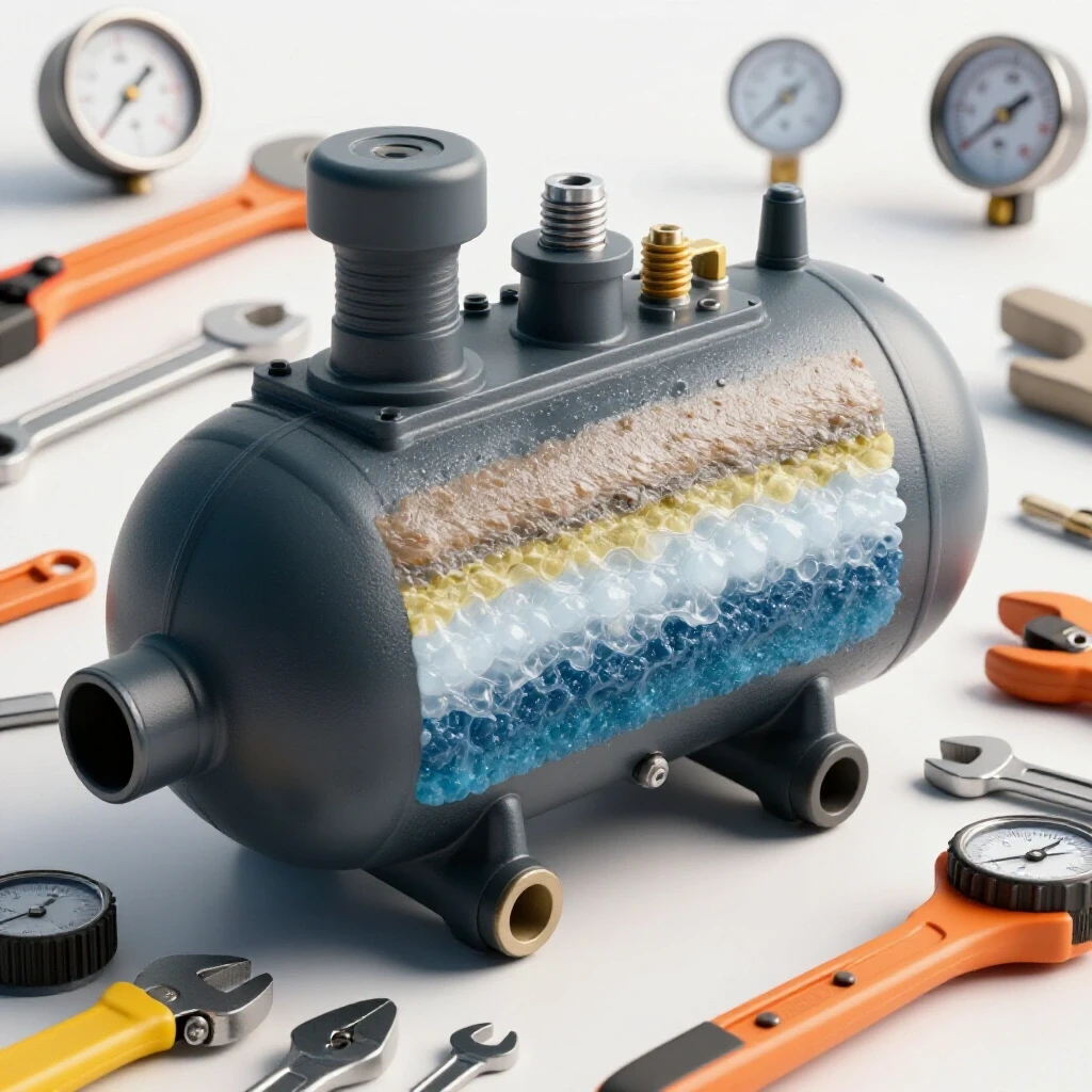
Water separators use centrifugal force to spin the air, flinging liquid droplets against the walls of a bowl where they can be drained. Desiccant dryers, on the other hand, use chemical beads (usually silica gel or activated alumina) to absorb water vapor at a molecular level. These systems are essential for achieving a “dry” air rating that won’t interfere with metallurgical processes or sensitive motor controllers.
Critical Metrics for Air Filtration
- Micron Rating: Most standard filters are 40 microns, but for precision work, you should look for 5-micron or even 0.01-micron coalescing filters.
- Flow Rate (CFM): Ensure your filter is rated for the maximum output of your compressor. An undersized filter will cause a massive pressure drop, leading to tool chatter and poor performance.
- Pressure Drop (PSI): A healthy filter should not cause a drop of more than 2-3 PSI. If you see a 10 PSI drop across a filter, the element is saturated or clogged.
- Dew Point Suppression: Desiccant dryers can lower the dew point of your air to -40 degrees Fahrenheit, ensuring no liquid forms even in freezing temperatures.
Building on this, it is important to remember that desiccant has a finite lifespan. Most beads change color (usually from blue to pink) when they are saturated. If you ignore this, the desiccant can actually break down and send “dust” down your lines, which is just as damaging to your tools as water.
A Systematic Maintenance Checklist for Air Quality Control
To maintain a shop that is free from moisture-related defects, you need a structured maintenance plan. You cannot wait for a weld to fail or a tool to seize before you take action. Systematic testing and logging will help you identify issues before they become expensive repairs.
I have found that keeping a simple logbook near the compressor helps maintain accountability. If you notice the volume of water increasing during your weekly drain, it might indicate that your shop’s humidity has risen or that your aftercooler fins are clogged with dust.
Essential Tools for Air System Diagnostics
- Digital Hygrometer: To monitor the ambient humidity in your shop.
- Infrared Thermometer: To check the temperature of the air entering and leaving the tank.
- Pressure Gauges (Inlet/Outlet): To monitor pressure drops across filters.
- Ultrasonic Leak Detector: To find small air leaks that cause the compressor to run more often, generating more heat and moisture.
- Clear Inline Sight Glass: To visually inspect for liquid flow in the lines during tool operation.
Weekly Calibration and Inspection Steps
- Check the automated drain function by manually triggering the test button.
- Inspect the aftercooler for dust buildup and clean with compressed air if necessary.
- Verify the color of the desiccant beads in your final-stage filters.
- Measure the temperature of the tank surface during a heavy work cycle; it should not feel “hot” to the touch if your cooling system is working.
- Drain all “drip legs” in your hard-piping system to ensure no liquid has bypassed the main tank.
Case Study: Solving Persistent Porosity in a Custom Fabrication Shop
I once worked with a fabricator who was ready to sell his high-end TIG welder because he couldn’t stop getting “wormhole” porosity in his stainless steel welds. He had replaced his gas regulator and even his torch leads, but the problem persisted. When I arrived, I noticed his air compressor was located in a small, unventilated closet right next to his welding station.
The compressor was running hot, and because the closet was small, it was sucking in its own heated exhaust. The air entering the tank was nearly 200 degrees, and the tank itself was too hot to touch. We moved the compressor to a ventilated area, installed a simple copper aftercooler, and added a coalescing filter before his pneumatic clamps.
The results were immediate. The “sweating” inside his lines stopped, and his weld porosity vanished. The root cause wasn’t the welder at all; it was the thermal environment of his air storage. By cooling the air and giving the moisture a place to escape, we restored his shop’s productivity without spending a dime on new welding equipment.
Actionable Tracking Framework for Air System Health
To keep your equipment running at peak performance, use the following benchmarks. These values represent a “healthy” system for an intermediate to advanced fabrication environment.
- Tank Temperature: Should stay within 15-20°F of ambient shop temperature.
- Maximum Pressure Drop: No more than 5 PSI from the tank to the tool.
- Drain Interval (Manual): Minimum of once every 4 hours of run time.
- Filter Life: Replace elements every 6 months or when the pressure drop exceeds 10 PSI.
- Air Quality Target: ISO 8573-1 Class 2.4.1 (for high-end fabrication).
By adhering to these metrics, you eliminate one of the most frustrating variables in metalworking. You stop guessing why your tools are chattering or why your welds are failing and start relying on a stable, predictable system.
FAQ: Managing Moisture and Protecting Your Air System
How does water in the air lines cause tool chatter? Liquid water is much denser than air. When a “slug” of water hits the vanes of an air motor, it causes a sudden, momentary drop in RPM. This rapid fluctuation in speed creates a vibration that reflects through the tool and into the workpiece, resulting in the irregular surface finish we call chatter.
Why is my compressor producing more water than my neighbor’s? This is usually due to three factors: duty cycle, location, and ventilation. If your compressor runs more frequently, it generates more heat, which holds more moisture. If your shop is more humid or the compressor is in a poorly ventilated corner, the air cannot cool efficiently, leading to more condensation inside the tank.
Can I just use a water trap at the tool instead of at the tank? A water trap at the tool is a good “last line of defense,” but it shouldn’t be your only solution. If water is allowed to sit in the tank, it causes internal rust. Furthermore, a small trap can easily become overwhelmed by the volume of water produced by a large tank, leading to bypass.
Is it safe to use an old tank that has had water sitting in it? It depends on the extent of the corrosion. If you see large flakes of rust (scale) coming out of the drain, the tank walls may be thinned. I recommend a “hammer test” or an ultrasonic thickness test to ensure the steel is still within its original manufacturing tolerances before continuing use.
What is the best material for shop air lines to prevent moisture issues? Copper or specialized aluminum piping is best. These materials conduct heat well, helping to cool the air and drop moisture out of suspension. Avoid PVC, which is a safety hazard under pressure, and black iron pipe, which will rust internally when exposed to the moisture you are trying to manage.
How do I know if my desiccant is still working? Most desiccant beads are “indicating,” meaning they change color. If your beads are pink or white instead of blue or orange, they are saturated. You can often “recharge” silica gel by baking it in a dedicated oven at a low temperature until the color returns.
Does a refrigerated dryer replace the need for a tank drain? No. A refrigerated dryer is excellent at removing vapor from the air stream, but the tank itself will still experience some condensation as the air cools initially. You should always maintain a functional drain on the reservoir regardless of what downstream drying equipment you use.
Will a larger tank reduce the amount of water in my lines? Actually, a larger tank provides more surface area for cooling, which can lead to more condensation inside the tank. This is a good thing, provided you have an effective way to drain it, as it means less water is staying in the air and traveling to your tools.
Why does my plasma cutter nozzle keep burning out? Water is the enemy of plasma cutting. When liquid water enters the plasma torch, it turns to steam instantly, disrupting the arc’s geometry and causing “double-arcing.” This destroys the nozzle and electrode almost instantly. A dedicated desiccant dryer is usually required for clean plasma operations.
Can I use a standard automotive fuel filter for my air lines? No. Automotive filters are not designed for the pressures or the flow characteristics of compressed air. They can burst or restrict airflow so severely that your tools will lose all torque and begin to chatter. Always use filters rated for the specific CFM and PSI of your air system.
How often should I check my system for leaks? I recommend a monthly leak check. Small leaks cause the compressor to cycle more often than necessary. This keeps the air in the tank hotter for longer, which prevents moisture from settling out and forces it down the line toward your work.
What is the most cost-effective DIY way to dry air? The most effective low-cost solution is a combination of a copper aftercooler (to strip initial heat) and a series of vertical “drip legs” made of copper pipe. This uses basic physics to cool the air and trap liquid before it can reach your expensive tools or sensitive weld joints.
(This article was written by one of our staff writers, Paul Whitaker. Visit our Meet the Team page to learn more about the author and their expertise.)