Simple Labor Cost Spreadsheet Templates for Custom Fab (Fix)
I remember the exact moment I realized my shop had outgrown my ability to manage it by memory. I was standing over a half-finished steel gate, looking at a pile of offcuts that represented wasted profit, and I couldn’t tell you exactly how many hours I had sunk into the project. I had the tools—a decent welder, a manual mill, and a growing collection of clamps—but I lacked the systems. Transitioning from a hobbyist to a professional fabricator isn’t just about buying a CNC plasma table or upgrading your power supply. It is about moving from “working harder” to “working smarter” through data and deliberate shop design.
When you scale a fabrication business, the invisible bottlenecks are what kill your momentum. You might have the best welding technique in the county, but if you spend twenty minutes moving a sheet of 10-gauge steel because your layout is cramped, you are losing money. Over the last twenty years, I have learned that a high-output shop requires a marriage between physical efficiency and administrative clarity. This guide focuses on how to reorganize your space, manage your power, and use basic arithmetic to track your most expensive resource: your time.
Why Mapping Material Flow Loops Prevents Shop Congestion
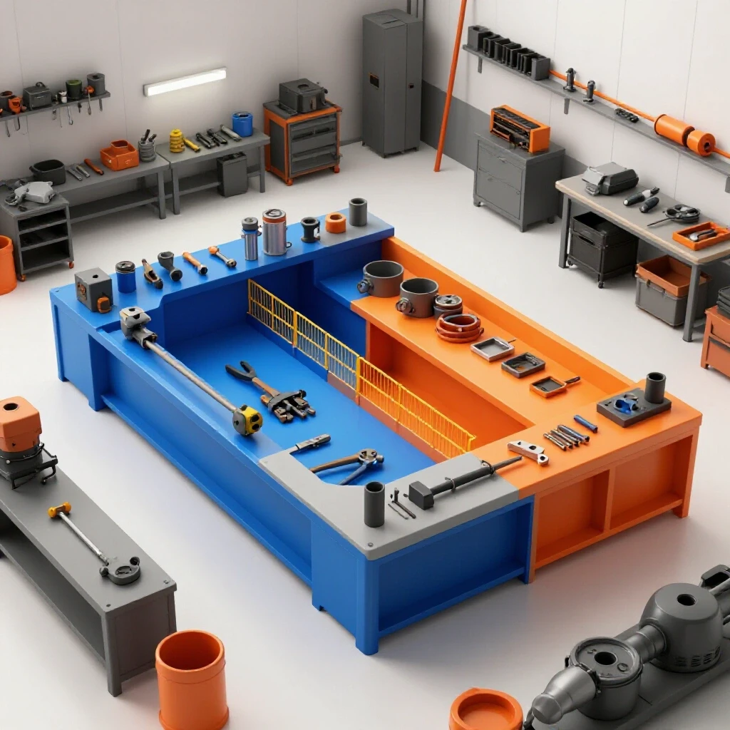
Material flow is the physical path a raw piece of metal takes from the moment it enters your shop until it leaves as a finished product. In an unoptimized shop, this path often looks like a tangled ball of yarn, with the fabricator crossing their own tracks multiple times. A professional layout seeks to create a linear or U-shaped path that minimizes the physical distance materials travel between stations.
When I first moved into a larger space, I made the mistake of putting my heavy plate rack in the back corner because that is where it fit. Every time I needed a sheet for the CNC table, I had to move three other projects and navigate a forklift through a narrow aisle. I eventually tracked my movement and realized I was spending four hours a week just moving material. By relocating the rack near the roll-up door and placing the primary cutting station adjacent to it, I reclaimed that time.
A successful layout relies on “machine zoning.” This means grouping tools by their function: a dirty zone for grinding and cutting, a clean zone for welding and assembly, and a tech zone for your CNC gantry and computer.
- Raw Material Entry: Keep this near your largest door to minimize forklift travel.
- Primary Cutting: Place your CNC plasma or cold saw within ten feet of your material storage.
- Deburring/Prep: This should be the next stop to ensure no dirty parts enter the welding zone.
- Welding/Assembly: This area requires the most floor space for jigs and fixtures.
- Finishing/Shipping: The final stop before the product exits the building.
Using Manual Time Tracking to Identify Production Bottlenecks
Manual time tracking is the process of recording the start and end times for specific fabrication tasks to determine the true cost of labor for a project. Instead of guessing how long a job took, a fabricator uses a basic grid to log hours spent on cutting, welding, and finishing. This data allows for more accurate bidding and identifies which processes are dragging down profitability.
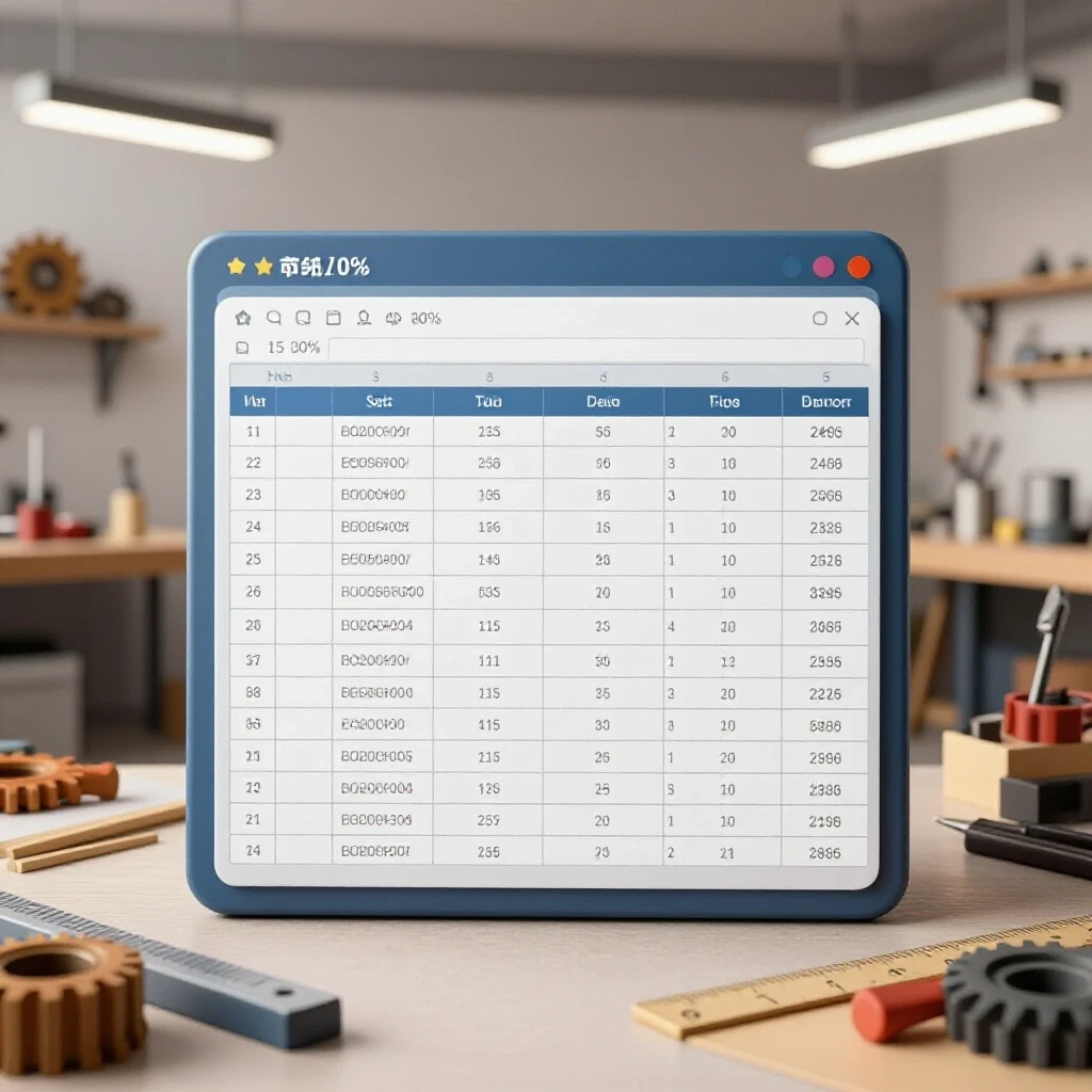
You do not need expensive software to understand your labor costs. A basic spreadsheet with simple arithmetic formulas is often more effective for a small shop. I use a generic setup with five main columns: Task Description, Start Time, End Time, Total Hours, and Hourly Rate. By using a simple multiplication formula (Total Hours * Hourly Rate), I can see exactly what a project cost me in labor.
Interestingly, when I started logging my time, I found that “prep work” often took longer than the actual welding. I was charging for the weld but losing my shirt on the grinding. If you see that your “Manual Prep” column is consistently high, it’s a signal that your abrasive tools or your material handling needs an upgrade.
| Task Category | Typical Formula | Purpose |
|---|---|---|
| Basic Labor Cost | Hours * Shop Rate |
Determines the baseline cost of a specific task. |
| Overhead Allocation | Labor Cost * 1.2 |
Adds a 20% buffer for electricity, gas, and consumables. |
| Total Project Time | SUM(Task A + Task B) |
Aggregates all recorded time logs for a single job. |
| Efficiency Ratio | Estimated Time / Actual Time |
Shows if you are getting faster or slower over time. |
Building Balanced 3-Phase Power Systems for Heavy Machinery
A 3-phase power system provides three alternating currents that are out of phase with each other, allowing for more efficient operation of heavy industrial motors. Most residential or small commercial buildings only have single-phase power, which limits the size and efficiency of the machines you can run. For an advancing shop, converting or bringing in 3-phase power is a critical step for running industrial-grade welders and CNC systems.
If your shop is in a residential area, getting a 3-phase drop from the utility company can cost tens of thousands of dollars. The more practical route for most of us is a Rotary Phase Converter (RPC). An RPC uses a 3-phase motor (the idler) and a bank of capacitors to “manufacture” the third leg of power from a single-phase source.
When I installed my first 15HP rotary converter, I learned the hard way about “voltage balance.” If the manufactured leg is too high or too low compared to the two pass-through legs, it can overheat your CNC electronics. I recommend checking the voltage across all three legs (L1-L2, L2-L3, and L1-L3) while the machine is under load. A balance within 5% is generally acceptable for most fabrication equipment.
- Static Converters: Cheap but only provide about 2/3 of the motor’s rated horsepower. Avoid these for CNC work.
- Rotary Phase Converters (RPC): The workhorse of the small shop. Reliable and can start multiple machines.
- Digital Phase Converters: The “gold standard.” They provide perfect sine-wave power but are significantly more expensive.
Designing High-Volume Clean Air Filtration and Duct Networks
Air quality management involves the use of collectors and filters to remove metal dust, smoke, and fumes from the shop environment. A professional system uses a central dust collector connected to various machines via a network of smooth-walled ducts. The goal is to maintain high air velocity to ensure particles stay suspended until they reach the filter.
In a small shop, “lung-powered” filtration (just wearing a respirator) isn’t enough when you add a CNC plasma table. Plasma cutting creates a massive amount of fine particulate that settles on everything. I designed my current system around a 2,000 CFM (Cubic Feet per Minute) cyclone collector.
The secret to a good duct network is minimizing “static pressure loss.” Every 90-degree elbow and every foot of flexible hose adds resistance. I use 6-inch rigid metal ducting for my main trunk line and 45-degree wyes instead of T-junctions to keep the air moving smoothly. If your air velocity drops below 3,500 feet per minute (FPM) in the ducts, heavy metal dust will settle in the pipes, eventually clogging the system and creating a fire hazard.
- CFM Requirements: A standard 4×4 plasma table usually requires at least 1,000 to 1,200 CFM for effective smoke evacuation.
- Static Pressure: This is the resistance the fan must overcome. More bends mean you need a more powerful motor.
- Filtration Grade: Look for HEPA or MERV 15+ filters to catch the smallest, most dangerous particles.
Successfully Integrating CNC Plasma Lines and Tooling Workflows
CNC integration is the process of moving from manual cutting to automated, computer-controlled fabrication. This requires not just the machine itself, but a digital workflow that includes CAD (Computer-Aided Design) for drawing, CAM (Computer-Aided Manufacturing) for toolpathing, and a post-processor to translate those paths into G-code for the machine.
The learning curve here is steep. I remember my first week with a CNC table; I crashed the torch head into a tip-up piece of scrap because I didn’t understand “lead-ins” and “tabs.” To avoid these bottlenecks, you must treat the CNC as a system, not just a tool. This means having a dedicated computer station that is shielded from grinding dust and a consistent method for naming and storing your cut files.
- Leveling the Slat Bed: If your table isn’t perfectly level, your torch height control (THC) will struggle, leading to poor cut quality or ruined nozzles.
- Air Quality for the Torch: Plasma cutters hate moisture. I use a three-stage drying system (refrigerated dryer, desiccant, and a motor guard filter) to ensure my air is bone-dry.
- Tooling Libraries: In your CAM software, create a library for every material thickness you cut. This saves you from re-entering “feed rates” and “pierce delays” every time you start a new job.
Analyzing the Capital Costs and Amortization of Shop Upgrades
Amortization is an accounting method used to spread the cost of a large equipment purchase over its useful life. For a shop owner, it is a tool to determine how much a machine needs to “earn” per hour to pay for itself. By dividing the total cost of the machine by the expected hours of use, you can set a realistic shop rate that covers your investment.
When I bought my $15,000 CNC table, I didn’t just look at the price tag. I looked at the “payback period.” If I use the machine 20 hours a week and it saves me 10 hours of manual labor, the machine pays for itself very quickly. I use a simple spreadsheet to track this. I list the initial cost, the monthly electricity increase, and the cost of consumables (like plasma electrodes).
- Initial Investment: The “out the door” price including shipping and electrical setup.
- Expected Life: For most pro-sumer CNC gear, I estimate a 5-year primary lifespan before major upgrades are needed.
- Hourly Machine Cost:
Total Investment / (Hours per Week * 52 Weeks * 5 Years).
If your machine costs you $5.00 an hour just to sit on the floor, you need to make sure your labor estimation formulas account for that “machine time” in addition to your “human time.”
Why Back-and-Forth Foot Traffic Kills Shop Throughput
Throughput is the rate at which your shop produces finished goods over a specific period. The biggest enemy of throughput is “non-value-added movement,” which is any time you spend walking, searching for tools, or moving obstacles. In a lean manufacturing environment, every step should serve a purpose.
I once spent a morning watching myself work. I realized I walked across the shop 15 times just to get different grits of flap discs. By creating “point-of-use” storage—placing a small drawer of abrasives directly at the grinding station—I cut my movement by 80%.
To fix your flow, try the “String Test.” Draw a map of your shop and use a pen to trace your path during a typical project. If the lines look like a spiderweb, your layout is failing you. Aim for a “U-flow” where the product enters one side of the door and exits the other, never doubling back.
- Standardize Your Tooling: Use the same brand of grinders so the wrenches and guards are interchangeable.
- Mobile Bases: Put everything that isn’t a stationary mill or lathe on heavy-duty casters. This allows you to reconfigure the shop for oversized projects.
- Shadow Boards: If a tool doesn’t have a specific home on a wall, it will end up buried under a pile of scrap.
Actionable Benchmarks for Your Workshop Evolution
As you transition to a more professional setup, you need specific metrics to aim for. These aren’t just guesses; they are industrial standards adapted for the advanced home-based or micro-manufacturing environment.
- Machine Spacing: Maintain a 3-foot “operator zone” around all stationary equipment. This ensures you have room to move safely and perform maintenance.
- Electrical Balance: Aim for no more than a 2% voltage drop at the furthest outlet when your largest motor starts up.
- Airflow Velocity: Ensure your dust collection maintains at least 4,000 FPM in the main trunk line for metal chips.
- Labor Tracking Accuracy: Your goal should be to get your “estimated vs. actual” time within a 10% margin of error.
By focusing on these metrics, you move away from the “hobbyist” mindset where time is free and into the “manufacturer” mindset where every minute is a commodity. It takes discipline to stop and log your hours or to spend a weekend moving a heavy workbench, but the result is a shop that feels like a precision instrument rather than a source of stress.
Frequently Asked Questions
How do I determine my hourly shop rate for a manual labor spreadsheet? Your shop rate is more than just what you want to earn. It must cover your “nut”—rent, electricity, insurance, and consumables—plus your desired profit. A common method is to add up all your monthly overhead costs, divide by the number of hours you work, and then add your target hourly wage. If your overhead is $1,000 and you work 160 hours, your overhead cost is $6.25/hr. If you want to make $40/hr, your base shop rate is $46.25.
What are the most important columns to include in a basic time-tracking log? For a clear picture of your shop’s efficiency, use columns for: Date, Project Name, Phase (e.g., Cutting, Welding, Finishing), Start Time, End Time, and Notes. The “Notes” column is vital for recording why a job took longer than expected—like a broken drill bit or a power outage.
Can I run a CNC plasma table on a rotary phase converter? Yes, but with caution. CNC electronics are sensitive to voltage spikes and imbalances. If you use an RPC, ensure it is “CNC rated,” which usually means it has additional capacitors to balance the voltage more precisely. Always measure the legs under load before connecting your expensive controller.
How often should I update the labor costs in my project estimates? I review my actual time logs against my estimates every quarter. If I find that I am consistently over my estimated time for “TIG Welding,” I either need to improve my skill, upgrade my equipment, or raise my prices for that specific task.
What is the best way to handle “administrative time” in a fabrication shop? Administrative time, like answering emails or ordering material, is often overlooked. You should either build this into your “Overhead” percentage or create a specific task category for it in your labor tracking. If you spend 5 hours a week on paperwork, that time must be paid for by the projects you finish.
How do I calculate the static pressure loss in my dust collection ducts? Static pressure loss is calculated by looking at the diameter of the pipe, its length, and the number of bends. Every 90-degree elbow is roughly equivalent to adding 10-15 feet of straight pipe. Most advanced fabricators use online calculators where you input your duct run details to ensure your collector has enough “lift” to move the air.
Why is linear flow better than a “work cell” layout for metal fab? A “work cell” is great for repeating the same small part thousands of times. However, custom fabrication often involves large, awkward items like trailers or frames. A linear or U-shaped flow is more flexible, allowing you to move large projects through the shop without hitting stationary “cells” of equipment.
What is the most common mistake when integrating CNC into a manual shop? The most common mistake is underestimating the “support equipment” needed. A CNC plasma table isn’t just the table; it requires a massive amount of dry air, a way to handle heavy sheets, and a robust smoke evacuation system. If you don’t budget for these, your table will sit idle while you scramble to fix environmental issues.
How do I track “wasted” time in a spreadsheet without feeling discouraged? The goal of tracking isn’t to punish yourself; it’s to find opportunities. If your log shows 30 minutes of “Searching for Tools” every day, that is a clear signal to invest in a better tool storage system. Data takes the emotion out of shop improvements.
Do I need a separate electrical sub-panel for my CNC equipment? While not strictly required by the NEC in all cases, a separate sub-panel for your CNC and “clean” electronics is a best practice. It helps isolate your sensitive controllers from the “dirty” electrical noise generated by large grinders and old-school transformer welders.
(This article was written by one of our staff writers, Edward Sinclair. Visit our Meet the Team page to learn more about the author and their expertise.)